EP0644487A2 - Structure échelonnable d'un système d'interruption pour un système à multi-programmes - Google Patents
Structure échelonnable d'un système d'interruption pour un système à multi-programmes Download PDFInfo
- Publication number
- EP0644487A2 EP0644487A2 EP94306762A EP94306762A EP0644487A2 EP 0644487 A2 EP0644487 A2 EP 0644487A2 EP 94306762 A EP94306762 A EP 94306762A EP 94306762 A EP94306762 A EP 94306762A EP 0644487 A2 EP0644487 A2 EP 0644487A2
- Authority
- EP
- European Patent Office
- Prior art keywords
- interrupt
- processor
- interrupts
- software
- priority
- Prior art date
- Legal status (The legal status is an assumption and is not a legal conclusion. Google has not performed a legal analysis and makes no representation as to the accuracy of the status listed.)
- Granted
Links
Images


Classifications
-
- G—PHYSICS
- G06—COMPUTING; CALCULATING OR COUNTING
- G06F—ELECTRIC DIGITAL DATA PROCESSING
- G06F13/00—Interconnection of, or transfer of information or other signals between, memories, input/output devices or central processing units
- G06F13/14—Handling requests for interconnection or transfer
- G06F13/20—Handling requests for interconnection or transfer for access to input/output bus
- G06F13/24—Handling requests for interconnection or transfer for access to input/output bus using interrupt
-
- G—PHYSICS
- G06—COMPUTING; CALCULATING OR COUNTING
- G06F—ELECTRIC DIGITAL DATA PROCESSING
- G06F9/00—Arrangements for program control, e.g. control units
- G06F9/06—Arrangements for program control, e.g. control units using stored programs, i.e. using an internal store of processing equipment to receive or retain programs
- G06F9/46—Multiprogramming arrangements
- G06F9/48—Program initiating; Program switching, e.g. by interrupt
- G06F9/4806—Task transfer initiation or dispatching
- G06F9/4812—Task transfer initiation or dispatching by interrupt, e.g. masked
Definitions
- This invention relates to data processing systems, and more particularly to a way of signalling interrupt information between an interrupt source and an interrupt processor in a data processing system.
- interrupts are used to signal a processor that an interrupt condition exists at a given source.
- This interrupt source could be, for example, an adapter card on a system bus which requires some type of service.
- the required service may be to initiate a transfer of data, or to read a status register that has recently changed.
- the processor When the processor has been conditioned to accept an interrupt, otherwise known as having the interrupts enabled, the processor will initiate interrupt processing upon the receipt of an interrupt.
- This interrupt processing typically involves the processor interrogating the source of the interrupt, performing functions based upon the type of interrupt, and resetting/turning off the interrupt.
- Interrupt priorities have also been accommodated in traditional systems. If more than one interrupt signal is active at a given time, the use of interrupt priorities tells the processor which interrupt to service first.
- Interrupt controllers have been designed to offload certain interrupt handshake functions that are required, such as resetting an interrupt signal.
- Typical of such interrupt controllers is an Intel 8259 controller, which is described in the Intel Component Data Catalog, 1981 (available from Intel Corp. Literature Department, 3065 Bowers Avenue, Santa Clara, CA), and hereby incorporated by reference as background material. These interrupt controllers can monitor multiple interrupt sources, and only interrupt the processor using a single interrupt line.
- a method is needed that is expandable, allowing many interrupt sources and priority levels.
- a method of signalling interrupt information is needed for use with multiprocessing systems that handle multiple processors and multiple interrupt controllers.
- the present invention provides, in a first aspect a system for maintaining a plurality of interrupts in a data processing system having a plurality of processors, comprising: means for routing said at least one of said plurality of interrupts to a particular processor; and means for queuing said at least one routed interrupt to said particular processor.
- the present invention provides a system for processing a plurality of interrupts in a multi-processor data processing system, comprising: an interrupt routing layer for receiving at least one interrupt, said routing layer having means for routing said at least one interrupt to a particular processor; and an interrupt presentation layer having means for receiving said at least one routed interrupt from said interrupt routing layer and means for queuing said at least one routed interrupt.
- the interrupt subsystem in which the present invention is preferably embodied is scalable from low-end uniprocessor systems to high-end multi-processor (MP) systems.
- This interrupt subsystem provides for queuing of interrupts from many sources, and for queuing of interrupts to the best processor in an MP system. This is achieved by separating the external interrupt mechanism into two layers, an interrupt routing layer and an interrupt presentation layer.
- the interrupt routing layer routes the interrupt conditions to the appropriate instance of an interrupt management area within the interrupt presentation layer.
- the interrupt routing layer is scalable to support both low-end/low-cost and high-end/high-performance systems.
- the interrupt presentation layer communicates the interrupt source to the system software which is to service/process the interrupt. This software accepts the interrupt condition and is responsible for resetting the interrupt condition. This software also indicates the acceptance of the interrupt and notifies the interrupt presentation layer that it has processed the interrupt.
- interrupt routing layer hides the details of a particular hardware implementation from the software.
- the interrupt presentation layer interfaces to the system and/or application software, and provides hardware independent functionality.
- an interrupt packet protocol is defined for both interrupt requests and interrupt resets.
- Address bus packets are used, and have many advantages over the hardwired method.
- I/O controller I/O controller
- the IOC requests the address bus.
- the IOC sends an interrupt request packet across the address bus.
- the interrupt controller processes the information and signals an interrupt to the processor.
- the interrupt controller may route the interrupt information to an appropriate processor.
- the processor is done processing the interrupt, it will alert the interrupt controller to send a reset packet to the IOC.
- the interrupt controller then requests the address bus. When granted the address bus, the interrupt controller sends an interrupt reset packet across the address bus.
- the data bus Since there are usually multiple cycles of data transfer for each address, the data bus is more heavily used than address bus.
- By sending interrupt information over the address bus it is possible to use an underutilized resource, the address bus, and not use the busier data bus.
- Another advantage of using the address bus is that, in the preferred embodiment, all the IC chips on the system bus use the entire address bus. However, these IC chips do not all use the entire data bus.
- the interrupt packets going over the address bus use the address lines already in the system at a cost of zero pins and zero wires. This is in contrast to prior methods, which use several distinct interrupt lines.
- memory mapped I/O is the most widely used method of performing input and output operations, it is used as the method for sending interrupt packets. Being the most common method of performing I/O, all the chips on the system bus already have logic to do memory-mapped I/O.
- the interrupt packet definition allows for 16 interrupt sources from each of 512 IOCs. There are 256 interrupt priority levels. Each system may have 256 interrupt servers. This allows the packet definition to be used in a wide range of machines. There are reserved bits in both the Interrupt Request Packet and Interrupt Reset Packet that may be used by systems that need to transmit more information in the interrupt packets. This packet definition thus allows for providing extendibility for future systems.
- Older hard-wired interrupt systems provided little immediate information about an interrupt.
- the bus packet method provides interrupt source, IOID, priority, and server information all at the same time and in the same place. In addition to system flexibility, this makes system interrupt debug much easier. Information can be put into the reserved address bits 0-2 of the Interrupt Reset Packet to tell the IOC which kind of Interrupt Reset is being sent.
- interrupts are transferred over the address bus, they are sequenced with other interrupts and with other system operations. This is helpful during debug because it makes interrupts more observable at a system level and less asynchronous to the system.
- interrupt information is defined in various fields in the interrupt packet instead of being hard-wired on the planar, this interrupt system is very programmable. Interrupt priority, server number, interrupt source and I/O controller ID are all programmable by using this packet structure. Thus, the interrupt structure is more flexible than those of hardwired systems.
- Figure 1 shows a block diagram of a data processing system.
- Figure 2 shows a block diagram of a device interface to a data processor through an interrupt controller.
- Figure 3 shows the components of a logical server interfacing to software queues.
- Figure 4 shows the internal structure of an interrupt controller.
- Figure 5 shows the hardware and software queue structure.
- Figure 6 shows a flowchart of the overall interrupt subsystem, including the I/O controller, the interrupt routing layer, and the interrupt presentation layer.
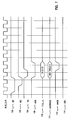
- Figure 7 shows a bus timing diagram for an interrupt request.
- Figure 8 shows a bus timing diagram for an interrupt reset.
- FIG. 1 illustrates the logical view of a data processing system 20.
- the system interconnect 22 allows for the transfer of data among the various components of the system: the processor 24, memory 26, and I/O 28 attached via an Input/Output Controller (IOC) 30 which is directly attached to the system interconnect 22.
- IOC Input/Output Controller
- the system interconnect 22 may be one of several different constructs (for example, a system bus, a switch, etc.) and is system dependent. In the preferred embodiment, the system interconnect is a system bus.
- the external interrupt structure for today's systems is required to span a wide range of system requirements; from the simple single user personal computer to multi-user systems consisting of a hierarchy of multiple processors. Previous techniques can not effectively address such a range.
- the programming interface to, and the logical view of, the interrupt system needs to be consistent.
- a typical interrupt structure is shown in Figure 2, wherein a device 32 (comprising I/O 28 and IOC 30 of Figure 1) capable of generating an interrupt is interfaced to a servicing processor 24 through an interrupt controller 34.
- This invention identifies an improved interrupt control structure which is scalable across a wide range of systems yet keeps a consistent programming model.
- each software queue 42 and 43 there exists a prioritized list of events. These events comprise hardware generated interrupts (e.g. external interrupts from the IOCs) and software generated interrupts (e.g. inter-processor interrupts).
- Each queue 42, 43 is associated with a logical server. Queues 0 through m are associated with logical server #0, and queues m+1 through n are associated with logical server #1. Additional logical servers having additional processors could similarly be configured. In a single processor system, there is one server and, therefore, one queue.
- FIG. 3 shows each queue 42 associated with a processor 40, and a global queue 44 associated with the collection of processors 0 through m.
- the collection of processors 40 is viewed as logical server #0 at 38.
- each queue 43 is associated with a processor 41, and a global queue 45 is associated with the collection of processors m+1 through n.
- the collection of processors 41 is viewed as logical server #1 at 39.
- APR Available Processor Register
- each queue 42, 43 associated with each queue 42, 43 is a server number in the range of 0x00 through 0xff.
- the individual processors 40, 41 within the complex are assigned server numbers ascending from 0x00, and queues which serve multiple processors (i.e. the global queues) are assigned server numbers descending from 0xff.
- Queue lengths i.e. the length of the prioritized list within the queue are implementation dependent, but have a minimum depth of one.
- External interrupts are sourced from IOC(s), other processors in the complex, and from other sources in the system (for example, an emergency power off warning interrupt). While the different sources require different physical signalling mechanisms, the logical appearance to the server (either the logical server for the global queues or the processor for other queues) is as one queue headed by the most favoured event, as will be further described below.
- the highest priority (i.e. most favoured) interrupt is defined to be 0x00 and the lowest priority interrupt (i.e. least favoured) is defined to be 0xff.
- interrupt level 0x55 is more favoured than interrupt level 0xff and less favoured than interrupt level 0x00.
- the interrupt presentation layer 50 comprises registers associated with processors or servers.
- the operating system software interfaces to these processors or servers to create and handle individual interrupts.
- the interrupt presentation layer 50 has a definition which only varies by the number of processors or servers within a system.
- the interrupt routing layer 52 routes the interrupts from the sources to the destinations and is by its nature far more implementation specific. System software may have to set up the configuration of the interrupt routing layer 52 at power-on time, but does not have to interface to this interrupt routing layer on a per interrupt basis.
- the goal of the interrupt routing layer is to direct the most favoured interrupt request to the processor operating at the least favoured priority, i.e. the best processor. To the best of its ability, the interrupt routing layer avoids sending an interrupt to a processor which is running at a more favoured level than the incoming request.
- This invention allows the interrupt routing layer to be implemented differently depending on the system requirements. Therefore, different implementations may approximate the above goal to different levels of accuracy and this will appear as a variable delay in the routing of interrupt requests. The greater the expected system load due to interrupts, the closer the interrupt routing hardware should approach the goal in order to achieve proper system performance.
- the interrupt routing hardware would have to be fully aware of the state of the system (that is, the exact per cycle processor priority, and the contents of all logical interrupt request queues). In practice this may not be possible because: (i) there may be more potential interrupt requests than the hardware queues within the interrupt routing layer; or (ii) the processor priority may take several cycles to propagate from the processor to the interrupt routing hardware, causing a certain level of uncertainty in the interrupt routing layer as to the exact per-cycle processor priority.
- the depth of queue problem is handled by requiring the IOCs to resubmit interrupt request messages that are rejected by the interrupt routing hardware.
- interrupt routing hardware This allows the interrupt routing hardware to implement a queue depth (minimum of one) to satisfy some percentage of the expected cases, with the interrupt rejection mechanism used to handle any overflow cases.
- the system software is unaware of the rejection mechanism which only exhibits a variable latency to affected interrupt requests. Since the interrupt routing hardware may be unaware of the true processor priority when it first routes a request toward a processor, the routing hardware must be prepared for the software to change its operating priority after the interrupt routing hardware has initially assigned a request to a specific processor.
- priority inversion can occur if an interrupt is queued which has a less favoured priority than the current processor priority, and if that queued interrupt prevents an interrupt with a more favoured priority than the processor from getting in and interrupting the processor); the queued interrupt will not get serviced until the processor drops down in priority below the queued interrupt priority.
- the interrupt rejection mechanism may be used to recover from queue resource problems. By rejecting the interrupt back to the IOC, the IOC acts as an extension to the interrupt routing layer queuing mechanism.
- An interrupt source will typically send a particular interrupt to the interrupt routing layer via interface 71 ( Figure 4) only once, unless one of the following occurs: (i) the interrupt is rejected by the interrupt routing layer; or (ii) the interrupt is reset by the software writing to the XIRR with an XISR value equal to the interrupt source and the interrupt for the interrupting source is still pending (i.e. has not yet been serviced). This will be further described below with reference to Figure 6.
- interrupt routing layer 52 Various implementations of the interrupt routing layer 52 are possible, including (i) a single element queue per processor consisting of an external interrupt priority and source for low-end machines, or (ii) multiple external interrupt source queue registers for high-end machines.
- the hardware assures that the exact hardware queuing implementation within the interrupt routing layer is transparent to the system software which interfaces to the interrupt presentation layer.
- queuing techniques known in the art that may be used, such as a hardware register file whose entities are kept in priority order, described in US patent 4,807,111 are hereby incorporated by reference.
- a key feature of the present invention is the use of such queues by an interrupt presentation layer. This interrupt presentation layer provides software transparency from the underlying queue implementation within the interrupt routing layer.
- the setup software must determine the Interrupt Routing Layer configuration, including how many logical servers are supported, which processors support which logical server, and which interrupts are to be directed to which server. This is done by reading some implementation specific registers, or by having the configuration information stored in ROM. APR's are used to specify which processors work against which logical server queue. The specific setup determination is hardware dependant, and will vary between differing hardware implementations. The only requirement is that the above listed setup information, however determined, is placed in the APRs for subsequent access by the interrupt routing layer.
- the inter-processor interrupt mechanism has a physical queue of request blocks (57 of Figure 5) in system memory that are associated with each queue 42, 43 of Figure 3. Each of these software-managed queues are maintained in priority order by the software. The implementation of the queue is not defined in the interrupt mechanism, but rather is left up to the operating system software. The implementation of the various queues may be different depending upon the expected frequency of use. Associated with each queue is a Most Favoured Request Register (MFRR) (in system memory space).
- MFRR Most Favoured Request Register
- a program When a program needs a service performed by a particular processor, it enqueues a request block to that processor's queue, it determines if the new request is at a more favoured priority, and if it is, the value of the new request's priority is written into the MFRR.
- the priority value of the next request on the queue is loaded into the MFRR. If the queue is empty after dequeue, the least favoured value (0xff) is loaded into the MFRR.
- a value other than 0xff in the MFRR indicates to the interrupt hardware in the interrupt routing layer that an interrupt of that priority should be signalled at 72 to a (the) processor which services that queue.
- Each processor has associated with it a memory mapped Interrupt Management Area which contains the external Interrupt Request Register (XIRR) 60.
- the XIRR is a 4-byte facility and is composed of two fields: the Current Processor Priority Register (CPPR) and the External Interrupt Source Register (XISR).
- the CPPR contains the processor's operating priority.
- the CPPR may be written by the system software to prevent interruptions from less favoured priority requests.
- the interrupt routing layer will only direct an interrupt request to a processor if its CPPR field is less favoured than the priority of the interrupt request.
- the system software stores to the CPPR as a 1-byte register to inform the interrupt hardware in the interrupt routing layer of the current operating priority of the processor.
- the system software reads the XISR by issuing a Load instruction to the XIRR.
- the value in the XISR specifies the source of the interrupt (if an IOC, which IOID and level; if a processor, which server queue). Based upon this information, the software can determine the proper program or process to invoke to service the interrupt.
- the XISR presents the appearance of a read only register from the interrupt routing layer for Load operations, and a write only register to the interrupt routing layer for Store operations.
- the XISR must be accessed atomically along with the CPPR when a 4-byte accesses is directed to the XIRR.
- the upper bits of the XISR indicate the IOC IOID, and the low order 4 bits of the XISR field define up to 16 sources (or levels) within an IOC. Several values of this register have defined meanings.
- the XISR will be further described below.
- the interrupt presentation layer of the interrupt mechanism is embodied through an Interrupt Management Area for each processor in the system, as shown below in Table 3.
- the Interrupt Management Area is within the data processing system's memory space.
- the starting address of the processor's interrupt management area is referred to as its Base Address (BA) for the rest of this document.
- the BA is different for each processor (that is, there is a separate Interrupt Management Area for each processor), and these areas can be accessed by any processor (there is no protection against it).
- the BA for a processor is setup at configuration time.
- Interrupt Management Area The layout of the Interrupt Management Area is as follows: Address Byte 0 Byte 1 Byte 2 Byte 3 Comments BA+0 CPPR XISR XIRR without side effects BA+4 CPPR XISR XIRR with Load/Store side effects BA+8 DSIER DSIER Data Storage Interrupt Error Register BA+12 MFRR ISSR Required QIRR BA+16 MFRR ISSR Optional 2nd QIRR BA+20 MFRR ISSR Optional 3rd QIRR 000 MFRR ISSR Optional nth QIRR TABLE 1: Interrupt Management Area: Interrupt Presentation Layer Registers
- FIG. 5 shows the interrelationship between the various queues previously described.
- the software queue 42, 43 that provides the consistent, hardware independent interface to the system software is shown for a particular processor X at 53. Queue X interfaces to processor X through the XIRR register shown at 54. This XIRR register can be modified by the interrupt routing layer 52 at 55. The step of selecting the highest priority by the routing layer at 55 must account for a plurality of interrupt types.
- Hardware interrupts which are maintained in a hardware queue at 56 are presented to the interrupt routing layer 52 at 58. These hardware interrupts are sourced from individual IOC hardware queues at 51.
- software generated interrupts may be presented to the interrupt routing layer 52. These software interrupts (e.g. inter-processor interrupts) are maintained in a software managed queue at 57, and presented to the interrupt routing layer at 59 through the MFRR register.
- the software queues 42 and 43 of Figure 4 which are presented to the system software are a combination of software-managed queues and hardware interrupt queues.
- the hardware queues can be distributed between the routing layer and the IOCs.
- the hardware-generated and software-managed queues are presented to the system software using a uniform interface, the XIRR register.
- an IOC When an IOC has an interrupt which needs servicing at 74, it first determines if this is the highest priority which needs to be presented. If there is a higher priority interrupt that has not been serviced yet, it will present that interrupt first at 75. The IOC will select the XIVR associated with the particular interrupt to be presented and will send the Server number and priority from the XIVR, along with the IOC IOID and a number indicating the source within the IOC which is requesting service to the interrupt routing layer at 76.
- the interrupt routing layer can use the server number from the interrupt information to direct at 77 the interrupt to a specific processor (server) 98 or if the server number does not correspond to a particular processor in the system, to choose which processor to which to route the interrupt at 78. How the hardware chooses to which processor to route the interrupt in this latter case is implementation dependent, and can be optimized based on the system design point (for example cost on the low end or performance on the high end). Information which comes into this routing decision block 78 is what priority the various processors are operating (the CPPR value) and what other priorities are queued up waiting for that processor (for example, the MFRR or G_MFRR for that processor).
- the interrupt is rejected at 96 back to the IOC, and the IOC must represent the interrupt at a later time (for example, after some fixed amount of time has elapsed). If the interrupt from the IOC is more favoured than an existing queued interrupt which has already been placed into the XIRR of the target processor 80, then the interrupt placed into the XIRR previously is rejected back to the IOC from which it came at 95, and the new interrupt takes its place at 81.
- an interrupt routing layer mechanism may chose to queue the interrupt in the routing layer for presentation at a later time, in the preferred embodiment the routing layer rejects the interrupt back to the source, and the source represents the interrupt at a later time.
- the loading of the XISR must be atomic; that is, the hardware must guarantee that the system software and interrupt routing layer are not trying to access the XISR simultaneously (for example, if the hardware is trying to update the XIRR with a higher priority request at the same time the processor was trying to read the XIRR).
- an interrupt is signalled to the processor by the hardware via the interrupt signal into the processor hardware.
- the software receives the interrupt signal and the interrupt processing begins at 85.
- the software at the beginning of the interrupt processing, reads the XIRR at 86 and saves that value away until the end of the interrupt processing.
- the hardware will place the priority of the interrupt represented by the XISR value into the CPPR and set the XISR to 0 at 86.
- the software After reading the XIRR, the software uses the value in the XISR field of the XIRR to determine what interrupt servicing routine to invoke. If the XISR points to the QIRR at 87, the software removes the most favoured queue entry from that queue and sets the MFRR in the QIRR to the value of the priority of the new most favoured entry on that queue 88 or to the value of 0xff, if the queue is then empty.
- the software removes the most favoured queue entry from the global queue and sets the G_MFRR in the G_QIRR to the value of the priority of the new most favoured entry on that queue at 90, or to the value of 0xff if the queue is then empty. If the XISR doesn't point to one of the software queues, then it points to an external interrupt service routine, and the software invokes the appropriate device driver to service the interrupt at 91.
- the device driver After the device driver has serviced the interrupt, it will reset the interrupt in the IOC during the course of the service routine (for example, most hardware would reset the interrupt in the IOC by issuing a store instruction to a certain address in the IOC's address space). No matter what the source of the interrupt, at the end of the servicing, the software will write the XIRR at BA+4 with the value which was read from the XISR and saved at the start of the interrupt servicing 92.
- the CPPR When the XIRR is written at BA+4, the CPPR will be set to the value in the store data (which, in this case, will be the value of the CPPR at the beginning of the interrupt servicing) and will issue an interrupt reset to the interrupt routing layer at 93 and IOC at 94 with the IOID and source within the IOC as specified in the XISR data that is written (which, in this case, will be the value of the XISR at the start of the interrupt, so this will reset the interrupt which has just been serviced).
- the IOC receives the reset, if the hardware still thinks that an interrupt is pending at 97 (for example, if the interrupt has occurred again since the software servicing and the write to the XIRR), then the interrupt presentation process starts over again at 74.
- Address BA+0 is designed to be used with interrupt polling.
- Address BA+4 has side effects when read or written, and is designed to allow efficient interrupt handler software by having the hardware assist the software in the interrupt queuing process.
- the registers and their use are further described below.
- the Most Favoured Request Register holds the priority of the most favoured request queued on a software managed queue for this processor.
- the MFRR competes with other external interrupts for the right to interrupt the processor.
- an appropriate value is loaded into the XISR (see XISR register description), and an interrupt is signalled to the processor.
- the processor reads the XIRR at BA+4, the value in the MFRR will be loaded by the hardware into the CPPR.
- the MFRR may be read back by the software to ensure that the MFRR write has been performed.
- the highest priority request is dequeued by the software from the software queue associated with the MFRR and the priority of the next favoured request is loaded into the MFRR by the software, using traditional queue management techniques known in the art.
- the system memory space contains one or more Global Queue MFRR's which are used by software to send inter-processor interrupts to any processor within some server group.
- the Global Queue MFRR's work just like the per processor MFRR described above except that the interrupt routing layer determines the processor to receive the request based upon its own algorithm, and the value loaded into the XISR is an IOID which indicates the Global Queue.
- This routing algorithm can similarly be optimized based upon the system design point. For example, a system optimized based on cost might route to a random processor to prevent from having to implement priority comparison logic, whereas a system which is implemented for high performance would attempt to always route to the processor which is running at the least favoured priority.
- Each IOC 30 contains one External Interrupt Vector register 70 for each external interrupt that it will support.
- the bits in each of these registers are defined as follows: BITS DESCRIPTION 0-15 Reserved: These bits are reserved and should be set to a value of 0 by the software on a Store instruction. These bits will be returned by the hardware as a value of a 0 on a Load instruction (software note: these bits are only guaranteed to be 0 as long as this field remains "reserved”: if these bits are redefined in the future, software may get back something other than 0).
- 16-23 Interrupt Server Number This determines where the interrupt is to be directed by the interrupt routing hardware. If the value represents a processor in the system, then the interrupt will be directed to that processor. If it does not correspond to a particular processor, then the interrupt routing layer can route based on its presentation algorithm. 24-31 Interrupt Priority: This field specifies what priority should be assigned to the incoming interrupt. Table 2: XIVR REGISTER DESCRIPTION
- registers reside in the IOC address space, and the addresses of these registers are defined by the particular design of the IOC.
- the XIRR is a 4-byte register at addresses BA+0 and BA+4. Issuing a Load instruction to the XIRR at address BA+0 causes the content of the CPPR and XISR to be sent to the processor with no side effects. This is designed for software polling of external interrupts. Issuing a Load instruction to the XIRR at address BA+4 has the following atomic side effects: Prior to returning the content of the XIRR:
- the processor When the system software begins to process an interrupt, the processor disables the interrupts -- masking off any subsequent external interrupts. During the interrupt processing sequence, the software must enable the interrupts to allow subsequent interrupts to be presented. Care must be taken to insure that the contents of the XIRR at BA+4 have been returned to the processor prior to enabling interrupts, in order to avoid a race with interrupt routing layer's interrupt signalling termination. Such a race can produce undefined results.
- One way to insure the data has returned, in the face of potential processor speculative instruction execution, is to place an XIRR value data dependency in the code prior to the code which enables the interrupts.
- the processor register which is receiving the XIRR value is compared with itself, and a branch-if-equal instruction is executed using the results of this comparison, with the branch target address being the next instruction location.
- This setting of the CPPR on the Load of the XIRR has the effect of rejecting all less favoured or equal priority external interrupts from the time that the software issues a Load instruction to the XIRR until it issues a Store instruction to the CPPR with a new value.
- Issuing a Store instruction to the XIRR facility at BA+0 is undefined (data is ignored). Storing to the XIRR at address BA+4 has atomic side effects and the effects are different for a 1-byte versus a 4-byte Store.
- the Store instruction is a 1-byte Store, then this is a Store to the CPPR (see CPPR Register description).
- the Store instruction is issued to the XIRR with a length of 4 bytes, an interrupt reset is sent to the source as indicated in the data that accompanies the Store to the XISR (not to the source indicated in the XISR at the time of the Store).
- the data that accompanies the Store to the XISR is not written into the XISR (and will not be obtained if subsequently read with a Load instruction). Rather, it is used to indicate the source to be reset to the interrupt routing layer (and to the IOC for interrupts other than inter-processor and global queue interrupts). Issuing a Store to the XISR at this address allows the source to present subsequent interrupts at the level indicated in the data accompanying the Store instruction.
- byte 0 is stored in the CPPR, but the system software ensures that this store of the CPPR is of a less favoured or equal priority than the previous CPPR value, because hardware is not required to handle dual resets for this case (one for the change in CPPR value to a more favoured or equal priority, and one for a write to the XISR).
- the interrupt routing layer hardware can do one of two things:
- the interrupt routing layer In order for the herein described interrupt mechanism to be used across differing systems potentially having different processors, the interrupt routing layer must insure that all interrupt signal constraints of a particular processor are met. If, for example, the processor does not internally latch the interrupt signal, and is not able to guarantee proper operation if the interrupt signal was deactivated during the processor's interrupt presentation cycle, then the interrupt routing layer should externally latch the interrupt signal resetting the latch with the read of the XISR rather than as the result of an interrupt rejection.
- writing the XIRR at BA+4 with the value read at the start of the interrupt handler has the combined effects of issuing an explicit end of interrupt to the IOC and returning the processor's operating priority to its pre-interrupt value.
- This register is a 1-byte register and is used to contain the current priority of the processor to which it is associated. This register is at addresses BA+0 and BA+4. Issuing a 1-byte Load to the CPPR (at either BA+0 or BA+4) has no side effects.
- the CPPR is a field in the XIRR register.
- Each processor has its own CPPR. When the processor changes state, software may store the process priority of the processor into the CPPR.
- the interrupt routing layer rejects all interrupts for a processor that are at a priority less favoured to the CPPR priority. Thus, keeping the CPPR current will prevent an external interrupt from interrupting a process of more favoured or equal priority.
- the CPPR is a field in the XIRR and can be read or written as part of the XIRR.
- the interrupt routing layer insures that only interrupts of more favoured level are signalled to the processor and are presented in the XIRR. This is accomplished using a hardware comparator. If the incoming interrupt priority is less than or equal to the current CPPR, then the interrupt is rejected back to the source.
- the hardware precompute (possibly by interrupt rejection) the most favoured interrupt to present after any Store to the CPPR if the direction of change of priority is to a less favoured priority, and it is mandatory if the Store to the CPPR is a more favoured or equal priority to any queued interrupt.
- the interrupt presentation hardware sets the XISR to a value of 0 (atomically, with the CPPR store), indicating that no interrupt is pending, and lowers the interrupt request line to the processor.
- This register is a 3-byte register and contains the address of the source of the interrupt.
- Each processor has its own XISR.
- This register is at address BA+1 and BA+5. However, this register must be accessed as part of the XIRR for purposes of atomicity.
- Issuing a Load instruction to the XIRR at address BA+0 causes the content of the XISR to be returned to the processor with no side effects. This is designed for software polling of external interrupts.
- Issuing a Load instruction to the XIRR at address BA+4 has the side effects of resetting the XISR to 0x000000 atomically after the contents of the XIRR have been returned to the processor. Subsequent interrupt requests of more favoured priority will then cause an interrupt to be signalled and presented in the XIRR.
- the Queued Interrupt Request Register is a 4 byte register with the first byte being the Most Favoured Request Register (MFRR) and the remaining low order 3 bytes as being the ISSR, if implemented.
- Software may write either a single byte, the MFRR, or a full four bytes.
- the content of this register is controlled by system software and indicates the most favoured interprocessor (IP) interrupt priority on an IP interrupt queue 42, 43 for the processor or server to which the particular MFRR is associated. If an MFRR for a processor is set to a value of 0xff, then there are no items in that IP interrupt queue 42, 43 for that processor, and the hardware is not to signal an IP interrupt to that processor.
- IP interprocessor
- an MFRR interrupt shall be resubmitted if and only if the interrupt condition has not been reset when either the interrupt is rejected by the routing layer or software issues the end of interrupt.
- the interrupt condition is taken to be an MFRR value other than Oxff. Therefore, once the MFRR has a non-0xff value, and the interrupt routing layer has started to route the interrupt, the interrupt routing layer will not reroute the interrupt request to the interrupt presentation layer because of a subsequent change of value in the MFRR.
- the only way that the interrupt routing layer will reroute the MFRR interrupt request is due to an interrupt rejection or an interrupt reset (given that the MFRR does not have the value 0xff).
- the MFRR's value is only changed by a software store operation.
- Each processor has at least one MFRR.
- the MFRR's associated with a specific processor's IP interrupt mechanism is located at an address of BA+12, BA+16, and so on.
- G_QIRR Global Queued Interrupt Request Register
- the Queued Interrupt Request Register 73 is a 4 byte register with the first byte being the Global Most Favoured Request Register (G_MFRR), which is an MFRR, and the remaining low order 3 bytes as being the ISSR.
- G_MFRR Global Most Favoured Request Register
- Software may write either a single byte, the G_MFRR, or a full four bytes.
- the starting address for the global server's interrupt management area is referred to as its base address (BA).
- BA base address
- the BA for each global server is different, and is established at setup time.
- the layout of the global server interrupt management area is as follows: Address Byte 0 Byte 1 Byte 2 Byte 3 Comments BA+12 G_MFRR ISSR Required QIRR for MP Systems BA+16 G_MFRR ISSR Optional 2 nd QIRR BA+20 G_MFRR ISSR Optional 3rd QIRR 000 G_MFRR ISSR Optional nth QIRR TABLE 4: Interrupt Management Area: Interrupt Presentation Layer Registers
- the ISSR Interrupt Source Specification Register
- the ISSR contains the value to be loaded into the XISR when the interrupt associated with the corresponding MFRR is signalled to a processor.
- Table 5 details the interrupt packet format designed for the IBM PowerPC 601 system bus. This system bus is further described in the "PowerPC 601 RISC Microprocessor User's Manual", 1992, and hereby incorporated by reference as background material. The same address bit definitions could similarly be used for other data processing machines using other processors.
- the Transfer Type bits are specific for the 601 bus and may change in other bus architectures.
- the transfer type field is used to identity the type of transfer occurring on the address bus, e.g. an interrupt request or an interrupt reset.
- the global (GBL) bit is used to indicate that every device on the bus should monitor the transaction, and is always enabled for interrupt packet transfer.
- the address bit lines are grouped into 4 subsets. Address bits 0-2 are used to provide further information for the particular type of transfer which is occurring. For an interrupt request operation, address bits 0-2 indicate whether this a first or subsequent presentation of an interrupt, and thus indicates whether this interrupt was previously rejected and is being re-submitted. For an interrupt reset operation, address bits 0-2 indicate the cause of the interrupt reset. Address bits 3-11 specify the system address or route of the requesting IOC.
- Address bits 12-15 identify which one of up to 16 sources within the IOC made the request.
- Address bits 16-23, the server number are taken directly from the XIVR register of the interrupt source. The server bits are compared, by each server, to the server number written to a configuration register at set-up time for that particular server.
- Address bits 24-31 in the request packet contain the interrupt's priority and also come from the XIVR of the interrupt source. These priority bits are compared against the current value if the CPPR to determine if an interrupt request will be accepted.
- Address bits 24-31 in the reset packet are reserved, and contain X'00'.
- FIGs 7 and 8 depict the bus signalling of the data processing interrupt subsystem.
- the IOC requests the address bus from the central bus arbitrator by activating its bus request signal, BR 100.
- the arbitrator grants the bus by activating the corresponding bus grant (BG) signal 102 to the IOC.
- the IOC then sends an interrupt request packet over the address bus. This is done by driving the transfer start (TS) 104, bus address 110 and transfer-type (TT) 108 lines to certain values (as defined in Table 5) to tell the interrupt controller there is an interrupt of a certain source and priority.
- signal address bus busy (ABB) 106 is driven low by the IOC to indicate that the address bus is in use.
- ABB signal address bus busy
- the interrupt controller processes the information and signals an interrupt to the processor.
- the interrupt controller may route the interrupt information to an appropriate processor, as previously described.
- the address acknowledgment signal (AACK) is driven low by the bus arbitrator to indicate that the address portion of the transaction has been completed.
- the processor when the processor is done processing the interrupt, it will alert the interrupt controller to send a reset packet to the IOC (storing to XIRR register, as previously discussed).
- the interrupt controller requests the address bus from the central bus arbitrator by activating its bus request signal, BR 100.
- the arbitrator grants the bus by activating the corresponding bus grant (BG) signal 102 to the IOC.
- the IOC sends an interrupt reset packet over the address bus. It does this by driving the TS 104, bus address 110 and TT 108 lines to certain values (as defined in Table 5) to tell the IOC that the interrupt has been serviced.
- signal address bus busy (ABB) 106 is driven low by the IOC to indicate that the address bus is in use.
- the address acknowledgment signal (AACK) is driven low by the bus arbitrator to indicate that the address portion of the transaction has been completed.
- a tenure consists of transferring one address and between 0 and 8 cycles of data. Since there are usually 4 cycles of data transfer for each address, the data bus is more heavily used than address bus. By sending interrupt information over the address bus, it is possible to use an underutilized resource, the address bus, and not use the busier data bus. Another advantage of using the address bus is that in the preferred embodiment, all IOCs currently on the system bus use the entire address bus. However, the IOCs do not all use the entire data bus. The interrupt packets going over the address bus use the address lines already in the system at a cost of zero pins and zero wires. This is in contrast to prior methods, which used several distinct interrupt lines.
- memory mapped I/O is the most widely used method of I/O, it is used as the method for sending interrupt packets. Being the most common method of I/O, and using traditional techniques known in the art, all the chips on the system bus already have logic to do memory-mapped I/O.
- the interrupt packet definition allows for 16 interrupt sources from each of 512 IOCs. There are 256 interrupt priority levels. Each system may have 256 interrupt servers. This allows the packet definition to be used in a wide range of machines. There are reserved bits in both the Interrupt Request Packet and Interrupt Reset Packet that may be used by systems that need to transmit more information in the interrupt packets. This packet definition thus allows for providing extendability for future systems.
- Older hard-wired interrupt systems provided little immediate information about an interrupt.
- the bus packet method provides interrupt source, IOID, priority, and server information all at the same time and in the same place. In addition to system flexibility, this makes system interrupt debug much easier. Information can be put into the reserved address bits 0-2 of the Interrupt Reset Packet to tell the IOC which kind of Interrupt Reset is being sent.
- Two hundred fifty six (256) possible interrupt servers are allowed in the interrupt packet definition. This means that up to two hundred fifty six (256) processors could be in the system receiving interrupts. This packet definition allows interrupts to be easily routed to different processors.
- the two hundred fifty six (256) possible interrupt servers can be defined for each system, to allow up to two hundred fifty six (256) interrupt controllers in a system. Each interrupt controller can service a single processor, or a batch of servers can service each processor, as previously described.
- interrupts are transferred over the address bus, they are sequenced with other interrupts and with other system operations. This is helpful during debug because it makes interrupts more observable at a system level and less asynchronous to the system.
- the system bus can be monitored to detect interrupts being presented on the address bus. Since the address packets are sequenced (i.e. not overlapped or concurrently presented), it is easier to determine what actions invoked or otherwise caused subsequent actions.
- interrupt information is defined in various fields in the interrupt packet instead of being hard-wired on the planar, this interrupt system is very programmable. Interrupt priority, server number, interrupt source and I/O controller ID are all programmable by using this packet structure. Thus, the interrupt structure is more flexible than those of hardwired systems.
Applications Claiming Priority (2)
| Application Number | Priority Date | Filing Date | Title |
|---|---|---|---|
| US12418293A | 1993-09-20 | 1993-09-20 | |
| US124182 | 1993-09-20 |
Publications (3)
| Publication Number | Publication Date |
|---|---|
| EP0644487A2 true EP0644487A2 (fr) | 1995-03-22 |
| EP0644487A3 EP0644487A3 (fr) | 1995-11-29 |
| EP0644487B1 EP0644487B1 (fr) | 1999-07-28 |
Family
ID=22413303
Family Applications (1)
| Application Number | Title | Priority Date | Filing Date |
|---|---|---|---|
| EP94306762A Expired - Lifetime EP0644487B1 (fr) | 1993-09-20 | 1994-09-15 | Structure échelonnable d'un système d'interruption pour un système à multi-programmes |
Country Status (8)
| Country | Link |
|---|---|
| US (1) | US5701495A (fr) |
| EP (1) | EP0644487B1 (fr) |
| JP (1) | JP3312266B2 (fr) |
| KR (1) | KR0128273B1 (fr) |
| CN (1) | CN1101026C (fr) |
| BR (1) | BR9403514A (fr) |
| CA (1) | CA2123447C (fr) |
| DE (1) | DE69419680T2 (fr) |
Cited By (4)
| Publication number | Priority date | Publication date | Assignee | Title |
|---|---|---|---|---|
| EP0875827A2 (fr) * | 1997-04-08 | 1998-11-04 | International Business Machines Corporation | Système d'interruption déclenché à source et destination pour notification de l'arrivée de messages |
| US6098105A (en) * | 1997-04-08 | 2000-08-01 | International Business Machines Corporation | Source and destination initiated interrupt method for message arrival notification |
| US6098104A (en) * | 1997-04-08 | 2000-08-01 | International Business Machines Corporation | Source and destination initiated interrupts for message arrival notification, and related data structures |
| EP1278133A2 (fr) | 2001-07-19 | 2003-01-22 | Fujitsu Limited | Système de recherche en texte intégral |
Families Citing this family (69)
| Publication number | Priority date | Publication date | Assignee | Title |
|---|---|---|---|---|
| US5835743A (en) * | 1994-06-30 | 1998-11-10 | Sun Microsystems, Inc. | Application binary interface and method of interfacing binary application program to digital computer |
| US5689713A (en) * | 1995-03-31 | 1997-11-18 | Sun Microsystems, Inc. | Method and apparatus for interrupt communication in a packet-switched computer system |
| US6034945A (en) | 1996-05-15 | 2000-03-07 | Cisco Technology, Inc. | Method and apparatus for per traffic flow buffer management |
| US6021456A (en) * | 1996-11-12 | 2000-02-01 | Herdeg; Glenn Arthur | Method for communicating interrupt data structure in a multi-processor computer system |
| US6236654B1 (en) * | 1997-02-14 | 2001-05-22 | Advanced Micro Devices, Inc. | Method and apparatus for managing learning in an address table in memory |
| US6201813B1 (en) | 1997-06-30 | 2001-03-13 | Cisco Technology, Inc. | Method and apparatus for using ATM queues for segmentation and reassembly of data frames |
| US6430191B1 (en) | 1997-06-30 | 2002-08-06 | Cisco Technology, Inc. | Multi-stage queuing discipline |
| US6487202B1 (en) | 1997-06-30 | 2002-11-26 | Cisco Technology, Inc. | Method and apparatus for maximizing memory throughput |
| US6526060B1 (en) * | 1997-12-05 | 2003-02-25 | Cisco Technology, Inc. | Dynamic rate-based, weighted fair scheduler with explicit rate feedback option |
| DE19882676T1 (de) * | 1998-02-16 | 2000-07-27 | Siemens Ag | Integrierte Schaltung |
| GB9809183D0 (en) * | 1998-04-29 | 1998-07-01 | Sgs Thomson Microelectronics | Microcomputer with interrupt packets |
| US6249906B1 (en) | 1998-06-26 | 2001-06-19 | International Business Machines Corp. | Adaptive method and system to minimize the effect of long table walks |
| US6134710A (en) * | 1998-06-26 | 2000-10-17 | International Business Machines Corp. | Adaptive method and system to minimize the effect of long cache misses |
| US6065088A (en) * | 1998-08-31 | 2000-05-16 | International Business Machines Corporation | System and method for interrupt command queuing and ordering |
| US6148361A (en) * | 1998-12-17 | 2000-11-14 | International Business Machines Corporation | Interrupt architecture for a non-uniform memory access (NUMA) data processing system |
| US6606716B1 (en) * | 1999-10-06 | 2003-08-12 | Dell Usa, L.P. | Method and system for automated technical support for computers |
| US6430643B1 (en) | 1999-09-02 | 2002-08-06 | International Business Machines Corporation | Method and system for assigning interrupts among multiple interrupt presentation controllers |
| US6845419B1 (en) * | 2000-01-24 | 2005-01-18 | Freescale Semiconductor, Inc. | Flexible interrupt controller that includes an interrupt force register |
| US6775292B1 (en) | 2000-01-24 | 2004-08-10 | Cisco Technology, Inc. | Method for servicing of multiple queues carrying voice over virtual circuits based on history |
| WO2001063416A1 (fr) * | 2000-02-24 | 2001-08-30 | Bops Incorporated | Procedes et dispositif de reaction et de detection d'interruption d'un processeur dans un groupement echelonnable |
| US7142558B1 (en) | 2000-04-17 | 2006-11-28 | Cisco Technology, Inc. | Dynamic queuing control for variable throughput communication channels |
| US6813666B2 (en) * | 2001-02-12 | 2004-11-02 | Freescale Semiconductor, Inc. | Scaleable arbitration and prioritization of multiple interrupts |
| US20020178313A1 (en) * | 2001-03-30 | 2002-11-28 | Gary Scott Paul | Using software interrupts to manage communication between data processors |
| US6940865B2 (en) * | 2001-04-17 | 2005-09-06 | Atheros Communications, Inc. | System and method for interleaving frames with different priorities |
| US7003611B2 (en) * | 2003-09-30 | 2006-02-21 | International Business Machines Corporation | Method and apparatus for handling interrupts using a set of interrupts servers associated with presentation controllers |
| US7831979B2 (en) * | 2004-04-28 | 2010-11-09 | Agere Systems Inc. | Processor with instruction-based interrupt handling |
| US20050283554A1 (en) * | 2004-06-22 | 2005-12-22 | General Electric Company | Computer system and method for queuing interrupt messages in a device coupled to a parallel communication bus |
| US7143223B2 (en) * | 2004-10-14 | 2006-11-28 | International Business Machines Corporation | Method, system and program product for emulating an interrupt architecture within a data processing system |
| JP4148223B2 (ja) * | 2005-01-28 | 2008-09-10 | セイコーエプソン株式会社 | プロセッサおよび情報処理方法 |
| US7386642B2 (en) * | 2005-01-28 | 2008-06-10 | Sony Computer Entertainment Inc. | IO direct memory access system and method |
| JP2006216042A (ja) * | 2005-02-04 | 2006-08-17 | Sony Computer Entertainment Inc | 割り込み処理のためのシステムおよび方法 |
| US7680972B2 (en) * | 2005-02-04 | 2010-03-16 | Sony Computer Entertainment Inc. | Micro interrupt handler |
| JP5243711B2 (ja) * | 2006-11-10 | 2013-07-24 | セイコーエプソン株式会社 | プロセッサ |
| US7882283B2 (en) * | 2006-11-27 | 2011-02-01 | Cisco Technology, Inc. | Virtualization support in a multiprocessor storage area network |
| US7844784B2 (en) | 2006-11-27 | 2010-11-30 | Cisco Technology, Inc. | Lock manager rotation in a multiprocessor storage area network |
| US8677014B2 (en) * | 2006-11-27 | 2014-03-18 | Cisco Technology, Inc. | Fine granularity exchange level load balancing in a multiprocessor storage area network |
| US8190561B1 (en) * | 2006-12-06 | 2012-05-29 | At&T Mobility Ii Llc | LDAP replication priority queuing mechanism |
| US7752370B2 (en) * | 2007-04-12 | 2010-07-06 | International Business Machines Corporation | Splitting one hardware interrupt to multiple handlers |
| US8019566B2 (en) * | 2007-09-11 | 2011-09-13 | International Business Machines Corporation | System and method for efficiently testing cache congruence classes during processor design verification and validation |
| US8099559B2 (en) * | 2007-09-11 | 2012-01-17 | International Business Machines Corporation | System and method for generating fast instruction and data interrupts for processor design verification and validation |
| US8006221B2 (en) | 2007-09-11 | 2011-08-23 | International Business Machines Corporation | System and method for testing multiple processor modes for processor design verification and validation |
| US20090070570A1 (en) * | 2007-09-11 | 2009-03-12 | Shubhodeep Roy Choudhury | System and Method for Efficiently Handling Interrupts |
| US7992059B2 (en) | 2007-09-11 | 2011-08-02 | International Business Machines Corporation | System and method for testing a large memory area during processor design verification and validation |
| US8607035B2 (en) * | 2008-08-29 | 2013-12-10 | Texas Instruments Incorporated | Multi-core processing utilizing prioritized interrupts for optimization |
| US8788782B2 (en) | 2009-08-13 | 2014-07-22 | Qualcomm Incorporated | Apparatus and method for memory management and efficient data processing |
| US8762532B2 (en) | 2009-08-13 | 2014-06-24 | Qualcomm Incorporated | Apparatus and method for efficient memory allocation |
| US9038073B2 (en) | 2009-08-13 | 2015-05-19 | Qualcomm Incorporated | Data mover moving data to accelerator for processing and returning result data based on instruction received from a processor utilizing software and hardware interrupts |
| MX337624B (es) | 2009-12-10 | 2016-03-11 | Royal Bank Of Canada | Procesamiento sincronizado de datos por recursos de computo conectados en red. |
| US9979589B2 (en) | 2009-12-10 | 2018-05-22 | Royal Bank Of Canada | Coordinated processing of data by networked computing resources |
| US10057333B2 (en) * | 2009-12-10 | 2018-08-21 | Royal Bank Of Canada | Coordinated processing of data by networked computing resources |
| US9959572B2 (en) * | 2009-12-10 | 2018-05-01 | Royal Bank Of Canada | Coordinated processing of data by networked computing resources |
| US9940670B2 (en) | 2009-12-10 | 2018-04-10 | Royal Bank Of Canada | Synchronized processing of data by networked computing resources |
| US8549202B2 (en) | 2010-08-04 | 2013-10-01 | International Business Machines Corporation | Interrupt source controller with scalable state structures |
| US8495271B2 (en) | 2010-08-04 | 2013-07-23 | International Business Machines Corporation | Injection of I/O messages |
| US9336029B2 (en) | 2010-08-04 | 2016-05-10 | International Business Machines Corporation | Determination via an indexed structure of one or more partitionable endpoints affected by an I/O message |
| US8261128B2 (en) | 2010-08-04 | 2012-09-04 | International Business Machines Corporation | Selection of a domain of a configuration access |
| KR101134557B1 (ko) * | 2010-12-23 | 2012-04-13 | 한전케이디엔주식회사 | 인터럽트 방식을 이용한 데이터 교환방법 및 이를 이용하는 지능형 전자장치 |
| US20120226842A1 (en) * | 2011-03-02 | 2012-09-06 | Research In Motion Limited, an Ontario, Canada corporation | Enhanced prioritising and unifying interrupt controller |
| US20130007533A1 (en) * | 2011-06-28 | 2013-01-03 | Miller Gary L | Data processing system having a sequence processing unit and method of operation |
| CN102855156B (zh) * | 2011-06-30 | 2015-05-27 | 重庆重邮信科通信技术有限公司 | 一种中断控制器及中断控制方法 |
| US10241923B2 (en) | 2012-11-06 | 2019-03-26 | International Business Machines Corporation | Configurable I/O address translation data structure |
| US9575912B2 (en) | 2014-04-08 | 2017-02-21 | Infineon Technologies Ag | Service request interrupt router with shared arbitration unit |
| CN103955410B (zh) * | 2014-05-23 | 2017-10-27 | 苏州国芯科技有限公司 | 基于多中断源优先级排序的中断控制方法 |
| US9779043B2 (en) | 2015-11-16 | 2017-10-03 | International Business Machines Corporation | Techniques for handling queued interrupts in a data processing system |
| US10248593B2 (en) | 2017-06-04 | 2019-04-02 | International Business Machines Corporation | Techniques for handling interrupts in a processing unit using interrupt request queues |
| US10210112B2 (en) | 2017-06-06 | 2019-02-19 | International Business Machines Corporation | Techniques for issuing interrupts in a data processing system with multiple scopes |
| US10438682B2 (en) | 2017-12-21 | 2019-10-08 | International Business Machines Corporation | List insertion in test segments with non-naturally aligned data boundaries |
| CN109271267B (zh) * | 2018-08-27 | 2022-11-22 | 北京达佳互联信息技术有限公司 | 路由数据处理方法、装置、电子设备及存储介质 |
| CN113220541B (zh) * | 2021-06-10 | 2021-09-07 | 北京全路通信信号研究设计院集团有限公司 | 一种多核处理器的内存巡检方法及系统 |
Citations (4)
| Publication number | Priority date | Publication date | Assignee | Title |
|---|---|---|---|---|
| US4604500A (en) * | 1981-12-02 | 1986-08-05 | At&T Bell Laboratories | Multiprocessing interrupt arrangement |
| US4860190A (en) * | 1985-09-03 | 1989-08-22 | Fujitsu Limited | Computer system for controlling virtual machines |
| WO1993000638A1 (fr) * | 1991-06-26 | 1993-01-07 | Ast Research, Inc. | Controleur de repartition automatique d'interruptions dans un systeme d'ordinateur a processeurs multiples |
| EP0602858A1 (fr) * | 1992-12-18 | 1994-06-22 | International Business Machines Corporation | Appareil et procédé permettant la prise en charge d'interruptions dans un système multiprocesseur |
Family Cites Families (26)
| Publication number | Priority date | Publication date | Assignee | Title |
|---|---|---|---|---|
| US4271468A (en) * | 1979-11-06 | 1981-06-02 | International Business Machines Corp. | Multiprocessor mechanism for handling channel interrupts |
| US4349873A (en) * | 1980-04-02 | 1982-09-14 | Motorola, Inc. | Microprocessor interrupt processing |
| US4413317A (en) * | 1980-11-14 | 1983-11-01 | Sperry Corporation | Multiprocessor system with cache/disk subsystem with status routing for plural disk drives |
| US4394727A (en) * | 1981-05-04 | 1983-07-19 | International Business Machines Corporation | Multi-processor task dispatching apparatus |
| JPS57191758A (en) * | 1981-05-20 | 1982-11-25 | Hitachi Ltd | System for storing test program in main storage |
| US4495569A (en) * | 1982-06-28 | 1985-01-22 | Mitsubishi Denki Kabushiki Kaisha | Interrupt control for multiprocessor system with storage data controlling processor interrupted by devices |
| US4530091A (en) * | 1983-07-08 | 1985-07-16 | At&T Bell Laboratories | Synchronization of real-time clocks in a packet switching system |
| JPS61107456A (ja) * | 1984-10-30 | 1986-05-26 | Toshiba Corp | 割込制御方式 |
| IT1184553B (it) * | 1985-05-07 | 1987-10-28 | Honeywell Inf Systems | Architettura di sistema a piu' processori |
| JPS62243058A (ja) * | 1986-04-15 | 1987-10-23 | Fanuc Ltd | マルチプロセツサシステムの割込制御方法 |
| US4914653A (en) * | 1986-12-22 | 1990-04-03 | American Telephone And Telegraph Company | Inter-processor communication protocol |
| US4807111A (en) * | 1987-06-19 | 1989-02-21 | International Business Machines Corporation | Dynamic queueing method |
| JPH0282343A (ja) * | 1988-09-20 | 1990-03-22 | Hitachi Ltd | マルチプロセッサシステムの割込処理方式 |
| US5109490A (en) * | 1989-01-13 | 1992-04-28 | International Business Machines Corporation | Data transfer using bus address lines |
| JPH0346051A (ja) * | 1989-07-14 | 1991-02-27 | Oki Electric Ind Co Ltd | マルチプロセッサシステムの割込み制御方式 |
| US5193187A (en) * | 1989-12-29 | 1993-03-09 | Supercomputer Systems Limited Partnership | Fast interrupt mechanism for interrupting processors in parallel in a multiprocessor system wherein processors are assigned process ID numbers |
| DE69029084D1 (de) * | 1990-02-27 | 1996-12-12 | Ibm | Nachrichtenführungseinrichtung durch mehrere Rechner, die mittels eines geteilten intelligenten Speichers gekoppelt sind |
| US5138709A (en) * | 1990-04-11 | 1992-08-11 | Motorola, Inc. | Spurious interrupt monitor |
| US5179707A (en) * | 1990-06-01 | 1993-01-12 | At&T Bell Laboratories | Interrupt processing allocation in a multiprocessor system |
| US5125093A (en) * | 1990-08-14 | 1992-06-23 | Nexgen Microsystems | Interrupt control for multiprocessor computer system |
| US5282272A (en) * | 1990-12-21 | 1994-01-25 | Intel Corporation | Interrupt distribution scheme for a computer bus |
| US5410710A (en) * | 1990-12-21 | 1995-04-25 | Intel Corporation | Multiprocessor programmable interrupt controller system adapted to functional redundancy checking processor systems |
| JP2855298B2 (ja) * | 1990-12-21 | 1999-02-10 | インテル・コーポレーション | 割込み要求の仲裁方法およびマルチプロセッサシステム |
| GB2259161B (en) * | 1991-08-24 | 1995-05-10 | Motorola Israel Ltd | System recovery |
| US5404535A (en) * | 1991-10-22 | 1995-04-04 | Bull Hn Information Systems Inc. | Apparatus and method for providing more effective reiterations of processing task requests in a multiprocessor system |
| US5381541A (en) * | 1993-05-26 | 1995-01-10 | International Business Machines Corp. | Computer system having planar board with single interrupt controller and processor card with plural processors and interrupt director |
-
1994
- 1994-05-12 CA CA002123447A patent/CA2123447C/fr not_active Expired - Fee Related
- 1994-08-10 JP JP18796194A patent/JP3312266B2/ja not_active Expired - Fee Related
- 1994-09-12 BR BR9403514A patent/BR9403514A/pt not_active Application Discontinuation
- 1994-09-15 EP EP94306762A patent/EP0644487B1/fr not_active Expired - Lifetime
- 1994-09-15 DE DE69419680T patent/DE69419680T2/de not_active Expired - Fee Related
- 1994-09-17 KR KR1019940023768A patent/KR0128273B1/ko not_active IP Right Cessation
- 1994-09-19 CN CN94116433A patent/CN1101026C/zh not_active Expired - Fee Related
-
1995
- 1995-12-18 US US08/573,918 patent/US5701495A/en not_active Expired - Fee Related
Patent Citations (4)
| Publication number | Priority date | Publication date | Assignee | Title |
|---|---|---|---|---|
| US4604500A (en) * | 1981-12-02 | 1986-08-05 | At&T Bell Laboratories | Multiprocessing interrupt arrangement |
| US4860190A (en) * | 1985-09-03 | 1989-08-22 | Fujitsu Limited | Computer system for controlling virtual machines |
| WO1993000638A1 (fr) * | 1991-06-26 | 1993-01-07 | Ast Research, Inc. | Controleur de repartition automatique d'interruptions dans un systeme d'ordinateur a processeurs multiples |
| EP0602858A1 (fr) * | 1992-12-18 | 1994-06-22 | International Business Machines Corporation | Appareil et procédé permettant la prise en charge d'interruptions dans un système multiprocesseur |
Non-Patent Citations (3)
| Title |
|---|
| : "Interrupt Dispatching Method for Multiprocessing System", IBM TECHNICAL DISCLOSURE BULLETIN, US, , vol. 27, no. 4B, pages 2356 to 2359 * |
| IBM TECHNICAL DISCLOSURE BULLETIN, vol. 33, no. 1A, June 1990 US, pages 245-247, XP 000120176 'Distributed control facility for interrupt and critical region' * |
| MICROPROCESSOR SYSTEMS: EUROMICRO SYMPOSIUM 1980, September 1980 LONDON, pages 157-166, K. M]HLEMANN 'Towards interrupt assignment for multiple processors' * |
Cited By (8)
| Publication number | Priority date | Publication date | Assignee | Title |
|---|---|---|---|---|
| EP0875827A2 (fr) * | 1997-04-08 | 1998-11-04 | International Business Machines Corporation | Système d'interruption déclenché à source et destination pour notification de l'arrivée de messages |
| EP0875827A3 (fr) * | 1997-04-08 | 1999-02-17 | International Business Machines Corporation | Système d'interruption déclenché à source et destination pour notification de l'arrivée de messages |
| US6098105A (en) * | 1997-04-08 | 2000-08-01 | International Business Machines Corporation | Source and destination initiated interrupt method for message arrival notification |
| US6098104A (en) * | 1997-04-08 | 2000-08-01 | International Business Machines Corporation | Source and destination initiated interrupts for message arrival notification, and related data structures |
| KR100298961B1 (ko) * | 1997-04-08 | 2001-09-06 | 포만 제프리 엘 | 메시지도착통지를위한소스및수신지개시인터럽트시스템 |
| EP1278133A2 (fr) | 2001-07-19 | 2003-01-22 | Fujitsu Limited | Système de recherche en texte intégral |
| EP1278133A3 (fr) * | 2001-07-19 | 2005-07-20 | Fujitsu Limited | Système de recherche en texte intégral |
| US7080069B2 (en) | 2001-07-19 | 2006-07-18 | Fujitsu Limited | Full text search system |
Also Published As
| Publication number | Publication date |
|---|---|
| DE69419680T2 (de) | 2000-03-02 |
| KR0128273B1 (ko) | 1998-04-15 |
| BR9403514A (pt) | 1995-06-20 |
| CA2123447A1 (fr) | 1995-03-21 |
| JP3312266B2 (ja) | 2002-08-05 |
| CA2123447C (fr) | 1999-02-16 |
| US5701495A (en) | 1997-12-23 |
| EP0644487A3 (fr) | 1995-11-29 |
| CN1101026C (zh) | 2003-02-05 |
| EP0644487B1 (fr) | 1999-07-28 |
| CN1120197A (zh) | 1996-04-10 |
| DE69419680D1 (de) | 1999-09-02 |
| JPH07105156A (ja) | 1995-04-21 |
| KR950009461A (ko) | 1995-04-24 |
Similar Documents
| Publication | Publication Date | Title |
|---|---|---|
| EP0644487B1 (fr) | Structure échelonnable d'un système d'interruption pour un système à multi-programmes | |
| EP0644489A2 (fr) | Méthode et appareil pour signaler des informations d'interruption dans un système de traitement de données | |
| JP3335172B2 (ja) | データ処理システム及びそれに使用するための入出力プロセッサ | |
| JP4034969B2 (ja) | 共通メモリのメモリ管理システム | |
| KR100292660B1 (ko) | 프로세서가통합된인터럽트제어기를갖춘멀티프로세서프로그래머블인터럽트제어기시스템 | |
| US6665699B1 (en) | Method and data processing system providing processor affinity dispatching | |
| EP0827085B1 (fr) | Procédé et dispositif pour la répartition des interruptions dans un système à multiprocesseur symétrique échelonnable sans changer la largeur de bus ou le protocole de bus | |
| US6553487B1 (en) | Device and method for performing high-speed low overhead context switch | |
| EP0511476A2 (fr) | Système multiprocesseur | |
| EP0737924A2 (fr) | Arbitrage de bus et transfert de données | |
| JPS5812611B2 (ja) | デ−タテンソウセイギヨホウシキ | |
| US4905145A (en) | Multiprocessor | |
| JPH1097509A (ja) | 対称型マルチプロセッサ・システムにおいて割り込みを分散する方法および装置 | |
| JPH056223B2 (fr) | ||
| AU603876B2 (en) | Multiple i/o bus virtual broadcast of programmed i/o instructions | |
| EP0742522B1 (fr) | Commande d'interruption de processeur | |
| US5944788A (en) | Message transfer system and control method for multiple sending and receiving modules in a network supporting hardware and software emulated modules | |
| US5999969A (en) | Interrupt handling system for message transfers in network having mixed hardware and software emulated modules | |
| US6889283B2 (en) | Method and system to promote arbitration priority in a buffer queue | |
| US5842003A (en) | Auxiliary message arbitrator for digital message transfer system in network of hardware modules | |
| JPH03263158A (ja) | 共通バス調停制御方式 | |
| US20050010711A1 (en) | Buffer page roll implementation for PCI-X block read transactions | |
| JPH01305461A (ja) | バス使用権制御方式 | |
| JP2976343B2 (ja) | 起動受け付け方法 | |
| JP2802091B2 (ja) | 割込ベクタ制御方式 |
Legal Events
| Date | Code | Title | Description |
|---|---|---|---|
| PUAI | Public reference made under article 153(3) epc to a published international application that has entered the european phase |
Free format text: ORIGINAL CODE: 0009012 |
|
| AK | Designated contracting states |
Kind code of ref document: A2 Designated state(s): DE FR GB |
|
| 17P | Request for examination filed |
Effective date: 19950714 |
|
| PUAL | Search report despatched |
Free format text: ORIGINAL CODE: 0009013 |
|
| AK | Designated contracting states |
Kind code of ref document: A3 Designated state(s): DE FR GB |
|
| 17Q | First examination report despatched |
Effective date: 19960612 |
|
| GRAG | Despatch of communication of intention to grant |
Free format text: ORIGINAL CODE: EPIDOS AGRA |
|
| GRAG | Despatch of communication of intention to grant |
Free format text: ORIGINAL CODE: EPIDOS AGRA |
|
| GRAH | Despatch of communication of intention to grant a patent |
Free format text: ORIGINAL CODE: EPIDOS IGRA |
|
| GRAH | Despatch of communication of intention to grant a patent |
Free format text: ORIGINAL CODE: EPIDOS IGRA |
|
| GRAH | Despatch of communication of intention to grant a patent |
Free format text: ORIGINAL CODE: EPIDOS IGRA |
|
| GRAA | (expected) grant |
Free format text: ORIGINAL CODE: 0009210 |
|
| AK | Designated contracting states |
Kind code of ref document: B1 Designated state(s): DE FR GB |
|
| REF | Corresponds to: |
Ref document number: 69419680 Country of ref document: DE Date of ref document: 19990902 |
|
| PGFP | Annual fee paid to national office [announced via postgrant information from national office to epo] |
Ref country code: FR Payment date: 19990917 Year of fee payment: 6 |
|
| ET | Fr: translation filed | ||
| PLBE | No opposition filed within time limit |
Free format text: ORIGINAL CODE: 0009261 |
|
| STAA | Information on the status of an ep patent application or granted ep patent |
Free format text: STATUS: NO OPPOSITION FILED WITHIN TIME LIMIT |
|
| 26N | No opposition filed | ||
| PG25 | Lapsed in a contracting state [announced via postgrant information from national office to epo] |
Ref country code: FR Free format text: LAPSE BECAUSE OF NON-PAYMENT OF DUE FEES Effective date: 20010531 |
|
| REG | Reference to a national code |
Ref country code: FR Ref legal event code: ST |
|
| PGFP | Annual fee paid to national office [announced via postgrant information from national office to epo] |
Ref country code: DE Payment date: 20010925 Year of fee payment: 8 |
|
| REG | Reference to a national code |
Ref country code: GB Ref legal event code: IF02 |
|
| PGFP | Annual fee paid to national office [announced via postgrant information from national office to epo] |
Ref country code: GB Payment date: 20020902 Year of fee payment: 9 |
|
| PG25 | Lapsed in a contracting state [announced via postgrant information from national office to epo] |
Ref country code: DE Free format text: LAPSE BECAUSE OF NON-PAYMENT OF DUE FEES Effective date: 20030401 |
|
| PG25 | Lapsed in a contracting state [announced via postgrant information from national office to epo] |
Ref country code: GB Free format text: LAPSE BECAUSE OF NON-PAYMENT OF DUE FEES Effective date: 20030915 |
|
| GBPC | Gb: european patent ceased through non-payment of renewal fee |
Effective date: 20030915 |