EP0644388A1 - Tieftemperaturzerlegung von Luft - Google Patents
Tieftemperaturzerlegung von Luft Download PDFInfo
- Publication number
- EP0644388A1 EP0644388A1 EP94306004A EP94306004A EP0644388A1 EP 0644388 A1 EP0644388 A1 EP 0644388A1 EP 94306004 A EP94306004 A EP 94306004A EP 94306004 A EP94306004 A EP 94306004A EP 0644388 A1 EP0644388 A1 EP 0644388A1
- Authority
- EP
- European Patent Office
- Prior art keywords
- stream
- heat exchanger
- main heat
- air
- air stream
- Prior art date
- Legal status (The legal status is an assumption and is not a legal conclusion. Google has not performed a legal analysis and makes no representation as to the accuracy of the status listed.)
- Granted
Links
Images

Classifications
-
- F—MECHANICAL ENGINEERING; LIGHTING; HEATING; WEAPONS; BLASTING
- F25—REFRIGERATION OR COOLING; COMBINED HEATING AND REFRIGERATION SYSTEMS; HEAT PUMP SYSTEMS; MANUFACTURE OR STORAGE OF ICE; LIQUEFACTION SOLIDIFICATION OF GASES
- F25J—LIQUEFACTION, SOLIDIFICATION OR SEPARATION OF GASES OR GASEOUS OR LIQUEFIED GASEOUS MIXTURES BY PRESSURE AND COLD TREATMENT OR BY BRINGING THEM INTO THE SUPERCRITICAL STATE
- F25J3/00—Processes or apparatus for separating the constituents of gaseous or liquefied gaseous mixtures involving the use of liquefaction or solidification
- F25J3/02—Processes or apparatus for separating the constituents of gaseous or liquefied gaseous mixtures involving the use of liquefaction or solidification by rectification, i.e. by continuous interchange of heat and material between a vapour stream and a liquid stream
- F25J3/04—Processes or apparatus for separating the constituents of gaseous or liquefied gaseous mixtures involving the use of liquefaction or solidification by rectification, i.e. by continuous interchange of heat and material between a vapour stream and a liquid stream for air
- F25J3/04151—Purification and (pre-)cooling of the feed air; recuperative heat-exchange with product streams
- F25J3/04187—Cooling of the purified feed air by recuperative heat-exchange; Heat-exchange with product streams
-
- F—MECHANICAL ENGINEERING; LIGHTING; HEATING; WEAPONS; BLASTING
- F25—REFRIGERATION OR COOLING; COMBINED HEATING AND REFRIGERATION SYSTEMS; HEAT PUMP SYSTEMS; MANUFACTURE OR STORAGE OF ICE; LIQUEFACTION SOLIDIFICATION OF GASES
- F25J—LIQUEFACTION, SOLIDIFICATION OR SEPARATION OF GASES OR GASEOUS OR LIQUEFIED GASEOUS MIXTURES BY PRESSURE AND COLD TREATMENT OR BY BRINGING THEM INTO THE SUPERCRITICAL STATE
- F25J3/00—Processes or apparatus for separating the constituents of gaseous or liquefied gaseous mixtures involving the use of liquefaction or solidification
- F25J3/02—Processes or apparatus for separating the constituents of gaseous or liquefied gaseous mixtures involving the use of liquefaction or solidification by rectification, i.e. by continuous interchange of heat and material between a vapour stream and a liquid stream
- F25J3/04—Processes or apparatus for separating the constituents of gaseous or liquefied gaseous mixtures involving the use of liquefaction or solidification by rectification, i.e. by continuous interchange of heat and material between a vapour stream and a liquid stream for air
- F25J3/04006—Providing pressurised feed air or process streams within or from the air fractionation unit
- F25J3/04048—Providing pressurised feed air or process streams within or from the air fractionation unit by compression of cold gaseous streams, e.g. intermediate or oxygen enriched (waste) streams
- F25J3/04054—Providing pressurised feed air or process streams within or from the air fractionation unit by compression of cold gaseous streams, e.g. intermediate or oxygen enriched (waste) streams of air
-
- F—MECHANICAL ENGINEERING; LIGHTING; HEATING; WEAPONS; BLASTING
- F25—REFRIGERATION OR COOLING; COMBINED HEATING AND REFRIGERATION SYSTEMS; HEAT PUMP SYSTEMS; MANUFACTURE OR STORAGE OF ICE; LIQUEFACTION SOLIDIFICATION OF GASES
- F25J—LIQUEFACTION, SOLIDIFICATION OR SEPARATION OF GASES OR GASEOUS OR LIQUEFIED GASEOUS MIXTURES BY PRESSURE AND COLD TREATMENT OR BY BRINGING THEM INTO THE SUPERCRITICAL STATE
- F25J3/00—Processes or apparatus for separating the constituents of gaseous or liquefied gaseous mixtures involving the use of liquefaction or solidification
- F25J3/02—Processes or apparatus for separating the constituents of gaseous or liquefied gaseous mixtures involving the use of liquefaction or solidification by rectification, i.e. by continuous interchange of heat and material between a vapour stream and a liquid stream
- F25J3/04—Processes or apparatus for separating the constituents of gaseous or liquefied gaseous mixtures involving the use of liquefaction or solidification by rectification, i.e. by continuous interchange of heat and material between a vapour stream and a liquid stream for air
- F25J3/04006—Providing pressurised feed air or process streams within or from the air fractionation unit
- F25J3/04078—Providing pressurised feed air or process streams within or from the air fractionation unit providing pressurized products by liquid compression and vaporisation with cold recovery, i.e. so-called internal compression
- F25J3/0409—Providing pressurised feed air or process streams within or from the air fractionation unit providing pressurized products by liquid compression and vaporisation with cold recovery, i.e. so-called internal compression of oxygen
-
- F—MECHANICAL ENGINEERING; LIGHTING; HEATING; WEAPONS; BLASTING
- F25—REFRIGERATION OR COOLING; COMBINED HEATING AND REFRIGERATION SYSTEMS; HEAT PUMP SYSTEMS; MANUFACTURE OR STORAGE OF ICE; LIQUEFACTION SOLIDIFICATION OF GASES
- F25J—LIQUEFACTION, SOLIDIFICATION OR SEPARATION OF GASES OR GASEOUS OR LIQUEFIED GASEOUS MIXTURES BY PRESSURE AND COLD TREATMENT OR BY BRINGING THEM INTO THE SUPERCRITICAL STATE
- F25J3/00—Processes or apparatus for separating the constituents of gaseous or liquefied gaseous mixtures involving the use of liquefaction or solidification
- F25J3/02—Processes or apparatus for separating the constituents of gaseous or liquefied gaseous mixtures involving the use of liquefaction or solidification by rectification, i.e. by continuous interchange of heat and material between a vapour stream and a liquid stream
- F25J3/04—Processes or apparatus for separating the constituents of gaseous or liquefied gaseous mixtures involving the use of liquefaction or solidification by rectification, i.e. by continuous interchange of heat and material between a vapour stream and a liquid stream for air
- F25J3/04151—Purification and (pre-)cooling of the feed air; recuperative heat-exchange with product streams
- F25J3/04187—Cooling of the purified feed air by recuperative heat-exchange; Heat-exchange with product streams
- F25J3/04193—Division of the main heat exchange line in consecutive sections having different functions
- F25J3/042—Division of the main heat exchange line in consecutive sections having different functions having an intermediate feed connection
-
- F—MECHANICAL ENGINEERING; LIGHTING; HEATING; WEAPONS; BLASTING
- F25—REFRIGERATION OR COOLING; COMBINED HEATING AND REFRIGERATION SYSTEMS; HEAT PUMP SYSTEMS; MANUFACTURE OR STORAGE OF ICE; LIQUEFACTION SOLIDIFICATION OF GASES
- F25J—LIQUEFACTION, SOLIDIFICATION OR SEPARATION OF GASES OR GASEOUS OR LIQUEFIED GASEOUS MIXTURES BY PRESSURE AND COLD TREATMENT OR BY BRINGING THEM INTO THE SUPERCRITICAL STATE
- F25J3/00—Processes or apparatus for separating the constituents of gaseous or liquefied gaseous mixtures involving the use of liquefaction or solidification
- F25J3/02—Processes or apparatus for separating the constituents of gaseous or liquefied gaseous mixtures involving the use of liquefaction or solidification by rectification, i.e. by continuous interchange of heat and material between a vapour stream and a liquid stream
- F25J3/04—Processes or apparatus for separating the constituents of gaseous or liquefied gaseous mixtures involving the use of liquefaction or solidification by rectification, i.e. by continuous interchange of heat and material between a vapour stream and a liquid stream for air
- F25J3/04248—Generation of cold for compensating heat leaks or liquid production, e.g. by Joule-Thompson expansion
- F25J3/04284—Generation of cold for compensating heat leaks or liquid production, e.g. by Joule-Thompson expansion using internal refrigeration by open-loop gas work expansion, e.g. of intermediate or oxygen enriched (waste-)streams
- F25J3/0429—Generation of cold for compensating heat leaks or liquid production, e.g. by Joule-Thompson expansion using internal refrigeration by open-loop gas work expansion, e.g. of intermediate or oxygen enriched (waste-)streams of feed air, e.g. used as waste or product air or expanded into an auxiliary column
- F25J3/04296—Claude expansion, i.e. expanded into the main or high pressure column
-
- F—MECHANICAL ENGINEERING; LIGHTING; HEATING; WEAPONS; BLASTING
- F25—REFRIGERATION OR COOLING; COMBINED HEATING AND REFRIGERATION SYSTEMS; HEAT PUMP SYSTEMS; MANUFACTURE OR STORAGE OF ICE; LIQUEFACTION SOLIDIFICATION OF GASES
- F25J—LIQUEFACTION, SOLIDIFICATION OR SEPARATION OF GASES OR GASEOUS OR LIQUEFIED GASEOUS MIXTURES BY PRESSURE AND COLD TREATMENT OR BY BRINGING THEM INTO THE SUPERCRITICAL STATE
- F25J3/00—Processes or apparatus for separating the constituents of gaseous or liquefied gaseous mixtures involving the use of liquefaction or solidification
- F25J3/02—Processes or apparatus for separating the constituents of gaseous or liquefied gaseous mixtures involving the use of liquefaction or solidification by rectification, i.e. by continuous interchange of heat and material between a vapour stream and a liquid stream
- F25J3/04—Processes or apparatus for separating the constituents of gaseous or liquefied gaseous mixtures involving the use of liquefaction or solidification by rectification, i.e. by continuous interchange of heat and material between a vapour stream and a liquid stream for air
- F25J3/04248—Generation of cold for compensating heat leaks or liquid production, e.g. by Joule-Thompson expansion
- F25J3/04284—Generation of cold for compensating heat leaks or liquid production, e.g. by Joule-Thompson expansion using internal refrigeration by open-loop gas work expansion, e.g. of intermediate or oxygen enriched (waste-)streams
- F25J3/0429—Generation of cold for compensating heat leaks or liquid production, e.g. by Joule-Thompson expansion using internal refrigeration by open-loop gas work expansion, e.g. of intermediate or oxygen enriched (waste-)streams of feed air, e.g. used as waste or product air or expanded into an auxiliary column
- F25J3/04303—Lachmann expansion, i.e. expanded into oxygen producing or low pressure column
-
- F—MECHANICAL ENGINEERING; LIGHTING; HEATING; WEAPONS; BLASTING
- F25—REFRIGERATION OR COOLING; COMBINED HEATING AND REFRIGERATION SYSTEMS; HEAT PUMP SYSTEMS; MANUFACTURE OR STORAGE OF ICE; LIQUEFACTION SOLIDIFICATION OF GASES
- F25J—LIQUEFACTION, SOLIDIFICATION OR SEPARATION OF GASES OR GASEOUS OR LIQUEFIED GASEOUS MIXTURES BY PRESSURE AND COLD TREATMENT OR BY BRINGING THEM INTO THE SUPERCRITICAL STATE
- F25J3/00—Processes or apparatus for separating the constituents of gaseous or liquefied gaseous mixtures involving the use of liquefaction or solidification
- F25J3/02—Processes or apparatus for separating the constituents of gaseous or liquefied gaseous mixtures involving the use of liquefaction or solidification by rectification, i.e. by continuous interchange of heat and material between a vapour stream and a liquid stream
- F25J3/04—Processes or apparatus for separating the constituents of gaseous or liquefied gaseous mixtures involving the use of liquefaction or solidification by rectification, i.e. by continuous interchange of heat and material between a vapour stream and a liquid stream for air
- F25J3/04248—Generation of cold for compensating heat leaks or liquid production, e.g. by Joule-Thompson expansion
- F25J3/04375—Details relating to the work expansion, e.g. process parameter etc.
- F25J3/04393—Details relating to the work expansion, e.g. process parameter etc. using multiple or multistage gas work expansion
-
- F—MECHANICAL ENGINEERING; LIGHTING; HEATING; WEAPONS; BLASTING
- F25—REFRIGERATION OR COOLING; COMBINED HEATING AND REFRIGERATION SYSTEMS; HEAT PUMP SYSTEMS; MANUFACTURE OR STORAGE OF ICE; LIQUEFACTION SOLIDIFICATION OF GASES
- F25J—LIQUEFACTION, SOLIDIFICATION OR SEPARATION OF GASES OR GASEOUS OR LIQUEFIED GASEOUS MIXTURES BY PRESSURE AND COLD TREATMENT OR BY BRINGING THEM INTO THE SUPERCRITICAL STATE
- F25J3/00—Processes or apparatus for separating the constituents of gaseous or liquefied gaseous mixtures involving the use of liquefaction or solidification
- F25J3/02—Processes or apparatus for separating the constituents of gaseous or liquefied gaseous mixtures involving the use of liquefaction or solidification by rectification, i.e. by continuous interchange of heat and material between a vapour stream and a liquid stream
- F25J3/04—Processes or apparatus for separating the constituents of gaseous or liquefied gaseous mixtures involving the use of liquefaction or solidification by rectification, i.e. by continuous interchange of heat and material between a vapour stream and a liquid stream for air
- F25J3/04406—Processes or apparatus for separating the constituents of gaseous or liquefied gaseous mixtures involving the use of liquefaction or solidification by rectification, i.e. by continuous interchange of heat and material between a vapour stream and a liquid stream for air using a dual pressure main column system
- F25J3/04412—Processes or apparatus for separating the constituents of gaseous or liquefied gaseous mixtures involving the use of liquefaction or solidification by rectification, i.e. by continuous interchange of heat and material between a vapour stream and a liquid stream for air using a dual pressure main column system in a classical double column flowsheet, i.e. with thermal coupling by a main reboiler-condenser in the bottom of low pressure respectively top of high pressure column
-
- F—MECHANICAL ENGINEERING; LIGHTING; HEATING; WEAPONS; BLASTING
- F25—REFRIGERATION OR COOLING; COMBINED HEATING AND REFRIGERATION SYSTEMS; HEAT PUMP SYSTEMS; MANUFACTURE OR STORAGE OF ICE; LIQUEFACTION SOLIDIFICATION OF GASES
- F25J—LIQUEFACTION, SOLIDIFICATION OR SEPARATION OF GASES OR GASEOUS OR LIQUEFIED GASEOUS MIXTURES BY PRESSURE AND COLD TREATMENT OR BY BRINGING THEM INTO THE SUPERCRITICAL STATE
- F25J2200/00—Processes or apparatus using separation by rectification
- F25J2200/50—Processes or apparatus using separation by rectification using multiple (re-)boiler-condensers at different heights of the column
- F25J2200/52—Processes or apparatus using separation by rectification using multiple (re-)boiler-condensers at different heights of the column in the high pressure column of a double pressure main column system
-
- F—MECHANICAL ENGINEERING; LIGHTING; HEATING; WEAPONS; BLASTING
- F25—REFRIGERATION OR COOLING; COMBINED HEATING AND REFRIGERATION SYSTEMS; HEAT PUMP SYSTEMS; MANUFACTURE OR STORAGE OF ICE; LIQUEFACTION SOLIDIFICATION OF GASES
- F25J—LIQUEFACTION, SOLIDIFICATION OR SEPARATION OF GASES OR GASEOUS OR LIQUEFIED GASEOUS MIXTURES BY PRESSURE AND COLD TREATMENT OR BY BRINGING THEM INTO THE SUPERCRITICAL STATE
- F25J2290/00—Other details not covered by groups F25J2200/00 - F25J2280/00
- F25J2290/10—Mathematical formulae, modeling, plot or curves; Design methods
Definitions
- This invention relates to air separation.
- Components of gaseous mixtures having different volatilities are separated from one another by a variety of well-known cryogenic rectification processes.
- Such processes utilize a main heat exchanger to cool the gaseous mixture to a temperature suitable for rectification after the gaseous mixture has been compressed.
- the rectification is carried out in distillation columns incorporating trays or packing (structured or random) to bring liquid and gaseous phases of the mixture into intimate contact and thereby separate the components of the mixture in accordance with their volatilities.
- the distillation is carried out such that the lower volatility component is produced in liquid form.
- the lower volatility component in the liquid form is then pumped to the delivery pressure and vaporized within the main heat exchanger.
- An important cryogenic rectification process concerns the separation of air.
- Air contains a lower volatility component, oxygen, and a higher volatility component, nitrogen.
- a liquid oxygen product of the cryogenic rectification of air is pumped to a delivery pressure and heated by incoming air in a heat exchanger from which it emerges as a pressurized gas.
- at least part of the air feed must be pressurized to a much higher pressure than the oxygen in order to provide the appropriate temperature difference in the heat exchanger. For instance, when an oxygen product, which amounts to about 21% of the incoming air by volume is pumped to 42.8 bar(a), about 35-40% of the incoming air is compressed to about 74.5 bar(a).
- the present invention provides a process and apparatus for the separation of air in which thermodynamic irreversibilities in the main heat exchanger are minimized. Additionally, the present invention also relates to a method of vaporizing a pumped low volatility product within a main heat exchanger, for instance, components of air, petrochemicals such that thermodynamic irreversibilities within the main heat exchanger are minimized.
- the invention provides a process as set out in Claim 5.
- air is compressed, heat of compression is removed from the air and the air is subsequently purified.
- the air is cooled in a main heat exchanger. Upstream of the cooling of the air, at least a portion of the air to be cooled is further compressed to form a further compressed air stream.
- the heat of compression is removed from the further compressed air stream.
- At least part of the further compressed air stream is removed from the main heat exchanger at a location of the main heat exchanger at which the further compressed air stream has a temperature in the vicinity of a theoretical pinch point temperature and at least a portion of the said part of the further compressed air stream removed from the main heat exchanger is still further compressed to form a first subsidiary air stream.
- This subsidiary air stream is introduced back into the main heat exchanger at a level thereof having a warmer temperature than the theoretical pinch point temperature. After reintroduction into the main heat exchanger, the first subsidiary air stream is fully cooled to a temperature suitable for its rectification.
- a part of the air to be cooled is removed from the main heat exchanger to form a second subsidiary air stream.
- the second subsidiary air stream is cooled to a temperature suitable for its rectification by expanding it with the performance of expansion work. At least part of the work of expansion is applied to the still further compression of the said portion of said part of the further compressed air stream removed from the heat exchanger.
- the air within the first and second subsidiary air streams is rectified within one or more rectification columns arranged such that a liquid oxygen fraction is produced. Refrigeration is supplied to the process to maintain an energy balance.
- a liquid oxygen stream which may be impure, is withdrawn from the said fraction and is pumped to the delivery pressure.
- the liquid oxygen stream is vaporized in the main heat exchanger such that it is fully warmed to ambient temperature and the liquid oxygen stream is extracted from the main heat exchanger as a gaseous oxygen product.
- the pinch point temperature is a temperature within the main heat exchanger where there exists a minimum difference in temperature between all the streams to be cooled in the main heat exchanger versus all the streams to be warmed in the main heat exchanger. Above and below this pinch point temperature, temperature differences and enthalpies diverge. The divergence is a measure of the thermodynamic irreversibility present within the main heat exchanger. This thermodynamic irreversibility represents lost work and therefore part of the energy requirements of the plant that are necessary in vaporizing the product oxygen stream.
- the term "theoretical pinch point temperature" as used herein and in the claims means the pinch point temperature determined for the collective cold streams in the main heat exchanger by for instance, simulation, that would exist if the first and second subsidiary air streams were never formed.
- the main heat exchanger would be operating in the manner of a known heat exchanger in which all of the further compressed air stream is fully cooled within the main heat exchanger.
- the heating and cooling curves were plotted as temperature versus enthalpy, the pinch point temperature and divergence of these curves would be readily apparent.
- the cooling and heating curves of a main heat exchanger operated in accordance with the present invention are compared with the known case, it can be seen that there is less divergence between the curves and therefore less lost work involved in vaporizing the pumped liquid oxygen stream.
- the use of the first subsidiary air stream reduces thermodynamic irreversibility between the theoretical pinch point temperature (which is typically substantially the same as the actual pinch point temperature) and the temperature at which the first subsidiary air stream is reintroduced into the main heat exchanger.
- the withdrawal of the second subsidiary air stream for cooling by work expansion rather than in the main heat exchanger lowers thermodynamic irreversibility below the theoretical and actual pinch point temperature.
- the first subsidiary air stream is generally taken from a first location and returned to a second location in the main heat exchanger selected so as to obtain a relatively close match between the temperature-enthalpy curve of the streams being warmed and that of the streams being cooled.
- main heat exchanger as used herein and in the claims is not necessarily limited to a single, (plate fin) heat exchanger.
- the terms “fully cooled” and “fully warmed” as used herein mean cooled to rectification temperature and warmed to ambient, respectively.
- partially in the context of “partially warmed” or “partially cooled”, as used herein means warmed or cooled to a temperature between fully warmed and fully cooled temperatures.
- vicinity as used herein with reference to a theoretical pinch point temperature means a temperature within a range of between plus or minus 50° C from the theoretical pinch point temperature.
- a main compressor for compressing the air.
- a first after-cooler communicates with the main compressor for removing heat of compression from the air and an air purification means communicates with the first after-cooler for purifying the air.
- a high pressure air compressor communicates with the air purification means for further compressing at least a portion of the air to form a further compressed air stream.
- a second after-cooler for removing the heat of compression from the compressed air stream communicates with the high pressure air compressor.
- a main heat exchanger is provided.
- the main heat exchanger has first and second passageways.
- the first passageway includes first and second sections and the first section thereof is in communication with the second after-cooler such that the compressed air stream flows into the first section of the first passageway.
- a means for discharging first and second subsidiary air streams composed of the compressed air stream from the first section of the passageway so that at least the first subsidiary stream upon discharge has a temperature in the vicinity of a theoretical pinch point temperature.
- An inlet is provided at a location of the main heat exchanger having a higher temperature than the theoretical pinch point temperature for receiving the first subsidiary air stream after the compression thereof.
- the second section of the first passageway is in communication with the inlet and position such that the first subsidiary air stream is fully cooled within the main heat exchanger.
- a heat pump compressor has an inlet communicating with the discharge means of the main heat exchanger and an outlet communicating with the inlet for the compressed first subsidiary air stream.
- An expansion means is provided for expanding the second subsidiary air stream with the performance of external work.
- the expansion means is coupled to the heat pump compressor such that at least part of the work is used to drive the heat pump compressor.
- An air rectification means communicates with the expansion means and the second section of the first passageway of the main heat exchanger for rectifying the air and thereby producing liquid oxygen.
- a pump communicates with the air rectification means and is operable to raise the liquid oxygen to the delivery pressure.
- the pump communicates with the second passageway of the main heat exchanger such that the pumped liquid oxygen stream flows in a countercurrent direction to the compressed air stream and is thereby vaporized to produce the gaseous oxygen product.
- a refrigeration means is provided for supplying refrigeration to the apparatus such that energy balance thereof is maintained.
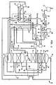
- a stream of air to be rectified is compressed in a main compressor 12 to form a compressed air stream 13.
- the heat of compression is removed from the compressed air stream 13 by a first after-cooler 14, typically water-cooled, and the compressed air stream 13 is purified by an air pre-purification unit 16 in which carbon dioxide, moisture and hydrocarbons are removed by adsorption from the air.
- a high pressure compressor 18 communicates with the air pre-purification unit 16 and operates to form a further compressed air stream 20.
- After passage through a second after-cooler 22 (to remove heat of compression from the further compressed air stream) the further compressed air stream 20 is introduced into a main heat exchanger 24.
- the main heat exchanger 24 has a first passageway 26 having first and second sections 26a and 26b in communication with a second after-cooler 22.
- the further compressed air stream 20 flows into first passageway 26.
- a second passageway 28 is provided for vaporizing a pumped liquid oxygen stream that will be discussed hereinafter.
- the first section 26a of first passageway 26 is provided with outlets for discharging first and second subsidiary air streams 30 and 32 from the main heat exchanger 24.
- the first subsidiary air stream 30 is yet further compressed within a heat pump compressor 34.
- a resulting compressed air stream 36 is introduced into the second section 26b of the first passageway 26 of the main heat exchanger 24 through an inlet communicating with a location in the heat exchanger 24 at a higher temperature than the theoretical or actual pinch point temperature.
- the second subsidiary air stream 32 is introduced into a turboexpander 38 that expands second subsidiary air stream 32 sufficiently that it is cooled to a temperature suitable for its rectification.
- the turboexpander 38 may be coupled to the heat pump compressor 34 mechanically.
- the compressor 34 may be driven by an electric motor (not shown).
- the necessary electrical power for operating the motor may be generated by the turboexpander 38 if the latter is coupled to an electrical generator.
- Excess energy, above that required to drive heat pump compressor 34 may be produced by turboexpander 38. In such case the excess energy could be applied elsewhere in the plant. For instance, excess electricity generated by the generator coupled to turboexpander 38 could be used for other electrical needs in the plant.
- the compressed air stream 13 is divided into first and second partial streams 40 and 42.
- the first partial stream 40 is subjected to further compression within high pressure air compressor 18.
- the second partial stream 42 is divided into third and fourth subsidiary air streams 44 and 46.
- the third subsidiary air stream 44 is fully cooled within a third passageway 48 of the main heat exchanger 24 provided for such purpose.
- the fourth subsidiary air stream 46 is further compressed within a refrigeration booster-compressor 50 and the heat of compression is removed by an after-cooler 52. With its heat of compression removed, the fourth subsidiary air stream 46 is partially cooled within a fourth passageway 54 of the main heat exchanger 24 provided for such purpose.
- the fourth subsidiary air stream 46 is withdrawn from main heat exchanger 24 and is passed through a refrigeration turboexpander 56 coupled to refrigeration booster compressor 50.
- the exhaust of refrigeration turboexpander 56 is returned through a fifth passageway 58 of the main heat exchanger 24.
- the main heat exchanger 24 is also provided with a sixth passageway 60 for fully warming a waste nitrogen stream (that will be discussed in more detail hereinafter) to ambient temperature and for use in regenerating pre-purification unit 16.
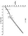
- the streams undergoing cooling must have a higher temperature than the streams being warmed. A point is reached though, where there is a minimum temperature difference, namely a pinch point temperature C.
- the distance between the curves, for instance distance D above the pinch point temperature and distance E below the pinch point temperature are indicative of the thermodynamic irreversibilities inherent within such a main heat exchanger. This thermodynamic irreversibility represents lost work, which translates into extra work of compression.
- Curve B' is the sum of the temperature enthalpy characteristics at any point witnin the main heat exchanger of all the streams to be warmed, namely oxygen stream 94 passing through passage 28 and the waste nitrogen stream 92 passing though passageway 60.
- the temperature difference between the curves at point D', (which is at a temperature higher than the actual pinch point temperature C' or the theoretical pinch point temperature C), and the temperature difference at point E' (which is at a temperature lower than the actual pinch point temperature C' or the theoretical pinch point temperature C) are much less than in the known heat exchanger.
- a double rectification column 62 comprising a high pressure column 64 and a low pressure column 66 operatively associated in a heat transfer relationship with one another by a condenser-reboiler 68.
- the air that has been is cooled to a temperature suitable for its rectification, namely at or near its dew point, is introduced into the high pressure column 64 so that an oxygen-rich liquid fraction forms at the bottom thereof and a nitrogen-rich fraction forms at the top of the column.
- the nitrogen-rich fraction is condensed by condenser-reboiler 68 to provide reflux for both the high and low pressure columns, the condensation being effected by indirect heat exchange with liquid oxygen collecting in the bottom of the low pressure column 66. A part of the liquid oxygen is thereby reboiled.
- Low pressure column 66 also produces a nitrogen vapour fraction at its top.
- the first subsidiary air stream 36 having been fully cooled, is introduced into a heat exchanger 70 located within the bottom of high pressure column 64 where it is further cooled.
- the further cooled first subsidiary air stream 36 is reduced in pressure to that of high pressure column 64 by a Joule-Thomson valve 72 and is downstream thereof introduced into high pressure column 64 for rectification.
- the heat exchanger 70 cools the air by indirect heat exchange with oxygen-rich liquid in the bottom of the high pressure column 64. Some of the oxygen-rich liquid vaporises and thus boil-up is created for the high pressure column 64.
- the second subsidiary air stream 32 downstream of its having been expanded by expander 38, is combined with fully cooled third subsidiary air stream 44 and is introduced into the bottom of the high pressure column 64 for rectification.
- the fourth subsidiary air stream 46 downstream of having been fully cooled within the fifth passageway 58 of main heat exchanger 24 is introduced into the low pressure column 66 for rectification.
- the high pressure column 64 is provided with contacting elements, for instance, structured packing, trays, or random packing designated by reference numeral 74.
- Low pressure column 66 is provided with such contacting elements, designated by reference numeral 76.
- a vapour phase becomes richer in the more volatile component, nitrogen, as it ascends and a liquid phase, as it descends, becomes more concentrated in the less volatile component, oxygen.
- Contacting elements 74 and 76 bring these two phases into intimate contact in order to effect the mass exchange.
- Oxygen-enriched liquid is withdrawn from the high pressure column 64 as a crude oxygen stream 78.
- the crude oxygen stream 78 is subcooled within subcooler 80 and is reduced in pressure by a Joule-Thomson valve 82 to the operating pressure of low pressure column 66 upstream of its introduction into the low pressure column 66.
- the condensed nitrogen-rich vapour of high pressure column 64 is divided into two streams 84 and 86 which are used to reflux high pressure column 64 and low pressure column 66, respectively.
- the stream 86 is subcooled in subcooler 80, reduced in pressure to that of low pressure column 66 by a Joule-Thomson valve 87 and introduced into the top of low pressure column 66.
- a reflux stream 88 having a composition near that of liquid air is withdrawn from high pressure column 64 and passed through subcooler 80.
- This reflux stream is passed through a Joule-Thomson valve 90 to reduce its pressure upstream of its introduction into low pressure column 66.
- This reflux stream 88 serves the purpose of optimizing the reflux conditions within high and low pressure columns 64 and 66.
- Waste nitrogen composed of the nitrogen vapour produced within the low pressure column 66 is withdrawn therefrom as a waste nitrogen stream 92.
- the waste nitrogen stream 92 is warmed within the subcooler 80 and is introduced into the sixth passageway 60 of the main heat exchanger 24 and warmed to ambient temperature.
- the warmed waste nitrogen stream may be vented from the plant but, as illustrated, may be supplied to purification unit 16 for regeneration purposes upstream of its being vented.
- the oxygen product is provided by removing a liquid oxygen stream 94 from low pressure column 66 and pumping it by a pump 96 to a delivery pressure.
- the pump 96 communicates with the second passageway 28 of the main heat exchanger.
- the liquid oxygen stream vaporizes therein and is warmed to ambient temperature and may be taken as a prescribed gaseous oxygen product.
- first and second subsidiary streams 30 and 32 are removed from separate points in main heat exchanger 24, it is possible to remove them at the same temperature.
- second subsidiary stream 32 is formed from part of further compressed air stream 20, it could also be formed from another air stream being cooled within main heat exchanger 24 or in case of an application other than air separation, some other process stream containing the gaseous mixture and being cooled within the main heat exchanger.
- the pinch point C' occurs at approximately the temperature at which the liquid oxygen stream starts to boil in the main heat exchanger. It is further to be understood that if the oxygen is required at its critical pressure (5043 kPa) or above there is no discrete change of phase of the oxygen in the main heat exchanger. References herein to vaporisation of liquid oxygen are thus intended to include within their scope the warming of a stream of oxygen at a supercritical pressure from below to above the critical temperature.
Landscapes
- Engineering & Computer Science (AREA)
- Physics & Mathematics (AREA)
- Mechanical Engineering (AREA)
- Thermal Sciences (AREA)
- General Engineering & Computer Science (AREA)
- Health & Medical Sciences (AREA)
- Emergency Medicine (AREA)
- Separation By Low-Temperature Treatments (AREA)
Applications Claiming Priority (2)
| Application Number | Priority Date | Filing Date | Title |
|---|---|---|---|
| US08/110,742 US5379598A (en) | 1993-08-23 | 1993-08-23 | Cryogenic rectification process and apparatus for vaporizing a pumped liquid product |
| US110742 | 1993-08-23 |
Publications (2)
| Publication Number | Publication Date |
|---|---|
| EP0644388A1 true EP0644388A1 (de) | 1995-03-22 |
| EP0644388B1 EP0644388B1 (de) | 1998-10-14 |
Family
ID=22334685
Family Applications (1)
| Application Number | Title | Priority Date | Filing Date |
|---|---|---|---|
| EP94306004A Expired - Lifetime EP0644388B1 (de) | 1993-08-23 | 1994-08-15 | Tieftemperaturzerlegung von Luft |
Country Status (12)
| Country | Link |
|---|---|
| US (1) | US5379598A (de) |
| EP (1) | EP0644388B1 (de) |
| JP (1) | JPH07174461A (de) |
| KR (1) | KR0137916B1 (de) |
| AU (1) | AU669998B2 (de) |
| CA (1) | CA2128565C (de) |
| DE (1) | DE69413918T2 (de) |
| FI (1) | FI943848A (de) |
| MY (1) | MY111904A (de) |
| NO (1) | NO942972L (de) |
| TW (1) | TW241331B (de) |
| ZA (1) | ZA945380B (de) |
Cited By (7)
| Publication number | Priority date | Publication date | Assignee | Title |
|---|---|---|---|---|
| FR2854683A1 (fr) * | 2003-05-05 | 2004-11-12 | Air Liquide | Procede et installation de production de gaz de l'air sous pression par distillation cryogenique d'air |
| FR2854682A1 (fr) * | 2003-05-05 | 2004-11-12 | Air Liquide | Procede et installation de separation d'air par distillation cryogenique |
| WO2005057112A1 (en) * | 2003-12-10 | 2005-06-23 | L'air Liquide, Societe Anonyme A Directoire Et Conseil De Surveillance Pour L'etude Et L'exploitation Des Procedes Georges Claude | Process and apparatus for the separation of air by cryogenic distillation |
| FR2864213A1 (fr) * | 2003-12-17 | 2005-06-24 | Air Liquide | Procede et installation de production sous forme gazeuse et sous haute pression d'au moins un fluide choisi parmi l'oxygene, l'argon et l'azote par distillation cryogenique de l'air |
| EP3312533A1 (de) * | 2016-10-18 | 2018-04-25 | Linde Aktiengesellschaft | Verfahren zur luftzerlegung und luftzerlegungsanlage |
| EP3438586A1 (de) * | 2017-08-03 | 2019-02-06 | L'air Liquide, Societe Anonyme Pour L'etude Et L'exploitation Des Procedes Georges Claude | Gerät und verfahren zur trennung von luft durch kryogene destillation |
| FR3069915A1 (fr) * | 2017-08-03 | 2019-02-08 | L'air Liquide, Societe Anonyme Pour L'etude Et L'exploitation Des Procedes Georges Claude | Appareil et procede de separation d'air par distillation cryogenique |
Families Citing this family (27)
| Publication number | Priority date | Publication date | Assignee | Title |
|---|---|---|---|---|
| FR2711778B1 (fr) * | 1993-10-26 | 1995-12-08 | Air Liquide | Procédé et installation de production d'oxygène et/ou d'azote sous pression. |
| US5475980A (en) * | 1993-12-30 | 1995-12-19 | L'air Liquide, Societe Anonyme Pour L'etude L'exploitation Des Procedes Georges Claude | Process and installation for production of high pressure gaseous fluid |
| US5463869A (en) * | 1994-08-12 | 1995-11-07 | Air Products And Chemicals, Inc. | Integrated adsorption/cryogenic distillation process for the separation of an air feed |
| US5551258A (en) * | 1994-12-15 | 1996-09-03 | The Boc Group Plc | Air separation |
| GB9425484D0 (en) * | 1994-12-16 | 1995-02-15 | Boc Group Plc | Air separation |
| US5560763A (en) * | 1995-05-24 | 1996-10-01 | The Boc Group, Inc. | Integrated air separation process |
| US5600970A (en) * | 1995-12-19 | 1997-02-11 | Praxair Technology, Inc. | Cryogenic rectification system with nitrogen turboexpander heat pump |
| US5611219A (en) * | 1996-03-19 | 1997-03-18 | Praxair Technology, Inc. | Air boiling cryogenic rectification system with staged feed air condensation |
| GB9726954D0 (en) * | 1997-12-19 | 1998-02-18 | Wickham Michael | Air separation |
| DE19843629A1 (de) * | 1998-09-23 | 2000-03-30 | Linde Ag | Verfahren und Verflüssiger zur Erzeugung von flüssiger Luft |
| US6178775B1 (en) * | 1998-10-30 | 2001-01-30 | The Boc Group, Inc. | Method and apparatus for separating air to produce an oxygen product |
| JP2000238449A (ja) * | 1999-02-18 | 2000-09-05 | Fuji Photo Film Co Ltd | 水なし平版印刷原版 |
| DE19908451A1 (de) * | 1999-02-26 | 2000-08-31 | Linde Tech Gase Gmbh | Zweisäulensystem zur Tieftemperaturzerlegung von Luft |
| DE19936816A1 (de) * | 1999-08-05 | 2001-02-08 | Linde Ag | Verfahren und Vorrichtung zur Gewinnung von Sauerstoff unter überatmosphärischem Druck |
| DE10155383A1 (de) * | 2001-11-10 | 2003-05-28 | Messer Ags Gmbh | Verfahren und Vorrichtung zur Tieftemperaturzerlegung von Luft |
| FR2851330B1 (fr) | 2003-02-13 | 2006-01-06 | Air Liquide | Procede et installation de production sous forme gazeuse et sous haute pression d'au moins un fluide choisi parmi l'oxygene, l'argon et l'azote par distillation cryogenique de l'air |
| US6732544B1 (en) * | 2003-05-15 | 2004-05-11 | Praxair Technology, Inc. | Feed air precooling and scrubbing system for cryogenic air separation plant |
| FR2865024B3 (fr) * | 2004-01-12 | 2006-05-05 | Air Liquide | Procede et installation de separation d'air par distillation cryogenique |
| US7272954B2 (en) * | 2004-07-14 | 2007-09-25 | L'air Liquide, Societe Anonyme A Directoire Et Conseil De Surveillance Pour L'etude Et L'exploitation Des Proceded Georges Claude | Low temperature air separation process for producing pressurized gaseous product |
| JP4519010B2 (ja) * | 2005-06-20 | 2010-08-04 | 大陽日酸株式会社 | 空気分離装置 |
| EP1767884A1 (de) * | 2005-09-23 | 2007-03-28 | L'Air Liquide Société Anon. à Directoire et Conseil de Surveillance pour l'Etude et l'Exploitation des Procédés Georges Claude | Verfahren und Vorrichtung zur Tieftemperaturzerlegung von Luft |
| FR2913760B1 (fr) * | 2007-03-13 | 2013-08-16 | Air Liquide | Procede et appareil de production de gaz de l'air sous forme gazeuse et liquide a haute flexibilite par distillation cryogenique |
| US7981256B2 (en) * | 2007-11-09 | 2011-07-19 | Uop Llc | Splitter with multi-stage heat pump compressor and inter-reboiler |
| US20090241595A1 (en) * | 2008-03-27 | 2009-10-01 | Praxair Technology, Inc. | Distillation method and apparatus |
| EP3179186A1 (de) * | 2015-12-07 | 2017-06-14 | Linde Aktiengesellschaft | Verfahren zur gewinnung eines flüssigen und eines gasförmigen, sauerstoffreichen luftprodukts in einer luftzerlegungsanlage und luftzerlegungsanlage |
| US10359231B2 (en) * | 2017-04-12 | 2019-07-23 | Praxair Technology, Inc. | Method for controlling production of high pressure gaseous oxygen in an air separation unit |
| FR3066809B1 (fr) | 2017-05-24 | 2020-01-31 | L'air Liquide, Societe Anonyme Pour L'etude Et L'exploitation Des Procedes Georges Claude | Procede et appareil pour la separation de l'air par distillation cryogenique |
Citations (4)
| Publication number | Priority date | Publication date | Assignee | Title |
|---|---|---|---|---|
| EP0454327A1 (de) * | 1990-04-18 | 1991-10-30 | The BOC Group plc | Lufttrennung |
| GB2251931A (en) * | 1991-01-15 | 1992-07-22 | Boc Group Plc | Air separation |
| EP0505812A1 (de) * | 1991-03-26 | 1992-09-30 | Linde Aktiengesellschaft | Verfahren zur Tieftemperaturzerlegung von Luft |
| EP0542539A1 (de) * | 1991-11-14 | 1993-05-19 | The BOC Group plc | Lufttrennung |
Family Cites Families (12)
| Publication number | Priority date | Publication date | Assignee | Title |
|---|---|---|---|---|
| BE547614A (de) * | 1955-05-31 | |||
| DE1501723A1 (de) * | 1966-01-13 | 1969-06-26 | Linde Ag | Verfahren und Vorrichtung zur Erzeugung gasfoermigen Hochdrucksauerstoffs bei der Tieftemperaturrektifikation von Luft |
| FR2461906A1 (fr) * | 1979-07-20 | 1981-02-06 | Air Liquide | Procede et installation cryogeniques de separation d'air avec production d'oxygene sous haute pression |
| US4817393A (en) * | 1986-04-18 | 1989-04-04 | Erickson Donald C | Companded total condensation loxboil air distillation |
| US4777803A (en) * | 1986-12-24 | 1988-10-18 | Erickson Donald C | Air partial expansion refrigeration for cryogenic air separation |
| DE3738559A1 (de) * | 1987-11-13 | 1989-05-24 | Linde Ag | Verfahren zur luftzerlegung durch tieftemperaturrektifikation |
| FR2652409A1 (fr) * | 1989-09-25 | 1991-03-29 | Air Liquide | Procede de production frigorifique, cycle frigorifique correspondant et leur application a la distillation d'air. |
| FR2652887B1 (fr) * | 1989-10-09 | 1993-12-24 | Air Liquide | Procede et installation de production d'oxygene gazeux a debit variable par distillation d'air. |
| JP2909678B2 (ja) * | 1991-03-11 | 1999-06-23 | レール・リキード・ソシエテ・アノニム・プール・レテュード・エ・レクスプロワタシオン・デ・プロセデ・ジョルジュ・クロード | 圧力下のガス状酸素の製造方法及び製造装置 |
| DE4126945A1 (de) * | 1991-08-14 | 1993-02-18 | Linde Ag | Verfahren zur luftzerlegung durch rektifikation |
| US5228296A (en) * | 1992-02-27 | 1993-07-20 | Praxair Technology, Inc. | Cryogenic rectification system with argon heat pump |
| US5251451A (en) * | 1992-08-28 | 1993-10-12 | Air Products And Chemicals, Inc. | Multiple reboiler, double column, air boosted, elevated pressure air separation cycle and its integration with gas turbines |
-
1993
- 1993-08-23 US US08/110,742 patent/US5379598A/en not_active Expired - Lifetime
-
1994
- 1994-07-14 TW TW083106418A patent/TW241331B/zh active
- 1994-07-21 ZA ZA945380A patent/ZA945380B/xx unknown
- 1994-07-21 CA CA002128565A patent/CA2128565C/en not_active Expired - Fee Related
- 1994-08-11 NO NO942972A patent/NO942972L/no unknown
- 1994-08-15 DE DE69413918T patent/DE69413918T2/de not_active Expired - Fee Related
- 1994-08-15 EP EP94306004A patent/EP0644388B1/de not_active Expired - Lifetime
- 1994-08-16 AU AU70290/94A patent/AU669998B2/en not_active Ceased
- 1994-08-22 FI FI943848A patent/FI943848A/fi not_active Application Discontinuation
- 1994-08-23 JP JP6198638A patent/JPH07174461A/ja not_active Ceased
- 1994-08-23 MY MYPI94002197A patent/MY111904A/en unknown
- 1994-08-23 KR KR1019940020741A patent/KR0137916B1/ko not_active IP Right Cessation
Patent Citations (4)
| Publication number | Priority date | Publication date | Assignee | Title |
|---|---|---|---|---|
| EP0454327A1 (de) * | 1990-04-18 | 1991-10-30 | The BOC Group plc | Lufttrennung |
| GB2251931A (en) * | 1991-01-15 | 1992-07-22 | Boc Group Plc | Air separation |
| EP0505812A1 (de) * | 1991-03-26 | 1992-09-30 | Linde Aktiengesellschaft | Verfahren zur Tieftemperaturzerlegung von Luft |
| EP0542539A1 (de) * | 1991-11-14 | 1993-05-19 | The BOC Group plc | Lufttrennung |
Cited By (14)
| Publication number | Priority date | Publication date | Assignee | Title |
|---|---|---|---|---|
| FR2854683A1 (fr) * | 2003-05-05 | 2004-11-12 | Air Liquide | Procede et installation de production de gaz de l'air sous pression par distillation cryogenique d'air |
| FR2854682A1 (fr) * | 2003-05-05 | 2004-11-12 | Air Liquide | Procede et installation de separation d'air par distillation cryogenique |
| WO2004099691A1 (fr) * | 2003-05-05 | 2004-11-18 | L'air Liquide Societe Anonyme A Directoire Et Conseil De Surveillance Pour L'etude Et L'exploitation Des Procedes Georges Claude | Procede et installation de production de gaz de l'air sous pression par distillation cryogenique d'air |
| WO2004099690A1 (fr) | 2003-05-05 | 2004-11-18 | L'air Liquide Societe Anonyme A Directoire Et Conseil De Surveillance Pour L'etude Et L'exploitation Des Procedes Georges Claude | Procede et installation de separation d'air par distillation cryogenique |
| US9945606B2 (en) | 2003-05-05 | 2018-04-17 | L'air Liquide Societe Anonyme Pour L'etude Et L'exploitation Des Procedes Georges Claude | Method and system for the production of pressurized air gas by cryogenic distillation of air |
| US7464568B2 (en) | 2003-05-05 | 2008-12-16 | L'air Liquide, Societe Anonyme A Directoire Et Conseil De Surveillance Pour L'etude Et L'exploitation Des Procedes Georges Claude | Cryogenic distillation method and system for air separation |
| US6962062B2 (en) | 2003-12-10 | 2005-11-08 | L'Air Liquide, Société Anonyme à Directoire et Conseil de Surveillance pour l'Etude et l'Exploitation des Proédés Georges Claude | Process and apparatus for the separation of air by cryogenic distillation |
| WO2005057112A1 (en) * | 2003-12-10 | 2005-06-23 | L'air Liquide, Societe Anonyme A Directoire Et Conseil De Surveillance Pour L'etude Et L'exploitation Des Procedes Georges Claude | Process and apparatus for the separation of air by cryogenic distillation |
| FR2864213A1 (fr) * | 2003-12-17 | 2005-06-24 | Air Liquide | Procede et installation de production sous forme gazeuse et sous haute pression d'au moins un fluide choisi parmi l'oxygene, l'argon et l'azote par distillation cryogenique de l'air |
| EP3312533A1 (de) * | 2016-10-18 | 2018-04-25 | Linde Aktiengesellschaft | Verfahren zur luftzerlegung und luftzerlegungsanlage |
| EP3438586A1 (de) * | 2017-08-03 | 2019-02-06 | L'air Liquide, Societe Anonyme Pour L'etude Et L'exploitation Des Procedes Georges Claude | Gerät und verfahren zur trennung von luft durch kryogene destillation |
| FR3069915A1 (fr) * | 2017-08-03 | 2019-02-08 | L'air Liquide, Societe Anonyme Pour L'etude Et L'exploitation Des Procedes Georges Claude | Appareil et procede de separation d'air par distillation cryogenique |
| US10794630B2 (en) | 2017-08-03 | 2020-10-06 | L'air Liquide Societe Anonyme Pour L'etude Et L'exploitation Des Procedes Georges Claude | Method and device for separating air by cryogenic distillation |
| US10866024B2 (en) | 2017-08-03 | 2020-12-15 | L'air Liquide, Societe Anonyme Pour L'etude Et L'exploitation Des Procedes Georges Claude | Device and method for separating air by cryogenic distillation |
Also Published As
| Publication number | Publication date |
|---|---|
| FI943848A0 (fi) | 1994-08-22 |
| DE69413918D1 (de) | 1998-11-19 |
| TW241331B (en) | 1995-02-21 |
| CA2128565C (en) | 1997-10-14 |
| AU669998B2 (en) | 1996-06-27 |
| CA2128565A1 (en) | 1995-02-24 |
| JPH07174461A (ja) | 1995-07-14 |
| KR0137916B1 (ko) | 1998-04-27 |
| KR950006409A (ko) | 1995-03-21 |
| US5379598A (en) | 1995-01-10 |
| MY111904A (en) | 2001-02-28 |
| AU7029094A (en) | 1995-03-02 |
| DE69413918T2 (de) | 1999-03-04 |
| FI943848A (fi) | 1995-02-24 |
| NO942972D0 (no) | 1994-08-11 |
| ZA945380B (en) | 1995-05-19 |
| EP0644388B1 (de) | 1998-10-14 |
| NO942972L (no) | 1995-02-24 |
Similar Documents
| Publication | Publication Date | Title |
|---|---|---|
| EP0644388B1 (de) | Tieftemperaturzerlegung von Luft | |
| EP0698772B1 (de) | Verfahren und Vorrichtung zur Herstellung von Sauerstoff | |
| EP0556516B1 (de) | Hochdrucklufttrennungszyklen, mit mehrfachem Aufkocher und Doppelkolonne und ihre Integration in Gasturbinen | |
| JP2758355B2 (ja) | 酸素と加圧窒素を製造するための低温空気分離方法 | |
| US5454227A (en) | Air separation method and apparatus | |
| EP0645595B1 (de) | Lufttrennungsschemas für die Koproduktion von Sauerstoff und Stickstoff als Gas- und/oder Flüssigprodukt | |
| US4707994A (en) | Gas separation process with single distillation column | |
| US5386692A (en) | Cryogenic rectification system with hybrid product boiler | |
| US4702757A (en) | Dual air pressure cycle to produce low purity oxygen | |
| JP2836781B2 (ja) | 空気分離方法 | |
| US4783210A (en) | Air separation process with modified single distillation column nitrogen generator | |
| US5582034A (en) | Air separation method and apparatus for producing nitrogen | |
| KR20080100362A (ko) | 초저온 공기 분리 시스템 | |
| JP2009509120A (ja) | 低温蒸留による空気の分離方法及び装置。 | |
| US5363657A (en) | Single column process and apparatus for producing oxygen at above-atmospheric pressure | |
| JP2002327981A (ja) | 3塔式深冷空気分離方法 | |
| EP0584420B1 (de) | Einsäulenluftzerlegungszyklus und dessen Integration in Gasturbinen | |
| JPH07151462A (ja) | 高圧の酸素及び窒素製品を製造する圧縮原料空気の低温分離法 | |
| US5839296A (en) | High pressure, improved efficiency cryogenic rectification system for low purity oxygen production | |
| US5379599A (en) | Pumped liquid oxygen method and apparatus | |
| JP3190016B2 (ja) | 高圧窒素を製造する原料空気の低温蒸留方法 | |
| JP2000346547A (ja) | 空気分離のための極低温蒸留 | |
| EP0932004A2 (de) | Vorrichtung zur Herstellung von Stickstoff | |
| EP0807792A2 (de) | Verfahren und Vorrichtung zur Lufttrennung | |
| CA2260722C (en) | Cryogenic rectification system with serial liquid air feed |
Legal Events
| Date | Code | Title | Description |
|---|---|---|---|
| PUAI | Public reference made under article 153(3) epc to a published international application that has entered the european phase |
Free format text: ORIGINAL CODE: 0009012 |
|
| AK | Designated contracting states |
Kind code of ref document: A1 Designated state(s): BE DE GB IT NL SE |
|
| 17P | Request for examination filed |
Effective date: 19950426 |
|
| 17Q | First examination report despatched |
Effective date: 19960329 |
|
| GRAG | Despatch of communication of intention to grant |
Free format text: ORIGINAL CODE: EPIDOS AGRA |
|
| GRAG | Despatch of communication of intention to grant |
Free format text: ORIGINAL CODE: EPIDOS AGRA |
|
| GRAH | Despatch of communication of intention to grant a patent |
Free format text: ORIGINAL CODE: EPIDOS IGRA |
|
| GRAH | Despatch of communication of intention to grant a patent |
Free format text: ORIGINAL CODE: EPIDOS IGRA |
|
| GRAA | (expected) grant |
Free format text: ORIGINAL CODE: 0009210 |
|
| AK | Designated contracting states |
Kind code of ref document: B1 Designated state(s): BE DE GB IT NL SE |
|
| REF | Corresponds to: |
Ref document number: 69413918 Country of ref document: DE Date of ref document: 19981119 |
|
| PLBQ | Unpublished change to opponent data |
Free format text: ORIGINAL CODE: EPIDOS OPPO |
|
| PLBI | Opposition filed |
Free format text: ORIGINAL CODE: 0009260 |
|
| PLBF | Reply of patent proprietor to notice(s) of opposition |
Free format text: ORIGINAL CODE: EPIDOS OBSO |
|
| 26 | Opposition filed |
Opponent name: LINDE AKTIENGESELLSCHAFT Effective date: 19990713 |
|
| PLBF | Reply of patent proprietor to notice(s) of opposition |
Free format text: ORIGINAL CODE: EPIDOS OBSO |
|
| PLBF | Reply of patent proprietor to notice(s) of opposition |
Free format text: ORIGINAL CODE: EPIDOS OBSO |
|
| PLBO | Opposition rejected |
Free format text: ORIGINAL CODE: EPIDOS REJO |
|
| PLBN | Opposition rejected |
Free format text: ORIGINAL CODE: 0009273 |
|
| STAA | Information on the status of an ep patent application or granted ep patent |
Free format text: STATUS: OPPOSITION REJECTED |
|
| 27O | Opposition rejected |
Effective date: 20000901 |
|
| NLR2 | Nl: decision of opposition | ||
| REG | Reference to a national code |
Ref country code: GB Ref legal event code: IF02 |
|
| PGFP | Annual fee paid to national office [announced via postgrant information from national office to epo] |
Ref country code: NL Payment date: 20040803 Year of fee payment: 11 |
|
| PGFP | Annual fee paid to national office [announced via postgrant information from national office to epo] |
Ref country code: SE Payment date: 20040806 Year of fee payment: 11 |
|
| PGFP | Annual fee paid to national office [announced via postgrant information from national office to epo] |
Ref country code: GB Payment date: 20040811 Year of fee payment: 11 |
|
| PGFP | Annual fee paid to national office [announced via postgrant information from national office to epo] |
Ref country code: DE Payment date: 20040826 Year of fee payment: 11 |
|
| PGFP | Annual fee paid to national office [announced via postgrant information from national office to epo] |
Ref country code: BE Payment date: 20041020 Year of fee payment: 11 |
|
| REG | Reference to a national code |
Ref country code: GB Ref legal event code: 732E |
|
| PG25 | Lapsed in a contracting state [announced via postgrant information from national office to epo] |
Ref country code: GB Free format text: LAPSE BECAUSE OF NON-PAYMENT OF DUE FEES Effective date: 20050815 |
|
| PG25 | Lapsed in a contracting state [announced via postgrant information from national office to epo] |
Ref country code: SE Free format text: LAPSE BECAUSE OF NON-PAYMENT OF DUE FEES Effective date: 20050816 |
|
| PG25 | Lapsed in a contracting state [announced via postgrant information from national office to epo] |
Ref country code: BE Free format text: LAPSE BECAUSE OF NON-PAYMENT OF DUE FEES Effective date: 20050831 |
|
| NLS | Nl: assignments of ep-patents |
Owner name: LINDE AG Effective date: 20050614 |
|
| PG25 | Lapsed in a contracting state [announced via postgrant information from national office to epo] |
Ref country code: NL Free format text: LAPSE BECAUSE OF NON-PAYMENT OF DUE FEES Effective date: 20060301 Ref country code: DE Free format text: LAPSE BECAUSE OF NON-PAYMENT OF DUE FEES Effective date: 20060301 |
|
| EUG | Se: european patent has lapsed | ||
| GBPC | Gb: european patent ceased through non-payment of renewal fee |
Effective date: 20050815 |
|
| NLV4 | Nl: lapsed or anulled due to non-payment of the annual fee |
Effective date: 20060301 |
|
| PGFP | Annual fee paid to national office [announced via postgrant information from national office to epo] |
Ref country code: IT Payment date: 20060831 Year of fee payment: 13 |
|
| BERE | Be: lapsed |
Owner name: *LINDE A.G. Effective date: 20050831 |
|
| PG25 | Lapsed in a contracting state [announced via postgrant information from national office to epo] |
Ref country code: IT Free format text: LAPSE BECAUSE OF NON-PAYMENT OF DUE FEES Effective date: 20070815 |