EP0642864B1 - A cutting tool - Google Patents
A cutting tool Download PDFInfo
- Publication number
- EP0642864B1 EP0642864B1 EP94114323A EP94114323A EP0642864B1 EP 0642864 B1 EP0642864 B1 EP 0642864B1 EP 94114323 A EP94114323 A EP 94114323A EP 94114323 A EP94114323 A EP 94114323A EP 0642864 B1 EP0642864 B1 EP 0642864B1
- Authority
- EP
- European Patent Office
- Prior art keywords
- insert
- jaw
- cutting
- clamping
- recess
- Prior art date
- Legal status (The legal status is an assumption and is not a legal conclusion. Google has not performed a legal analysis and makes no representation as to the accuracy of the status listed.)
- Expired - Lifetime
Links
Images


Classifications
-
- B—PERFORMING OPERATIONS; TRANSPORTING
- B23—MACHINE TOOLS; METAL-WORKING NOT OTHERWISE PROVIDED FOR
- B23C—MILLING
- B23C5/00—Milling-cutters
- B23C5/02—Milling-cutters characterised by the shape of the cutter
- B23C5/10—Shank-type cutters, i.e. with an integral shaft
- B23C5/1009—Ball nose end mills
- B23C5/1027—Ball nose end mills with one or more removable cutting inserts
- B23C5/1036—Ball nose end mills with one or more removable cutting inserts having a single cutting insert, the cutting edges of which subtend 180 degrees
-
- B—PERFORMING OPERATIONS; TRANSPORTING
- B23—MACHINE TOOLS; METAL-WORKING NOT OTHERWISE PROVIDED FOR
- B23C—MILLING
- B23C5/00—Milling-cutters
- B23C5/16—Milling-cutters characterised by physical features other than shape
- B23C5/20—Milling-cutters characterised by physical features other than shape with removable cutter bits or teeth or cutting inserts
- B23C5/22—Securing arrangements for bits or teeth or cutting inserts
- B23C5/2239—Securing arrangements for bits or teeth or cutting inserts with cutting inserts clamped by a clamping member acting almost perpendicular on the cutting face
- B23C5/2243—Securing arrangements for bits or teeth or cutting inserts with cutting inserts clamped by a clamping member acting almost perpendicular on the cutting face for plate-like cutting inserts
- B23C5/2247—Securing arrangements for bits or teeth or cutting inserts with cutting inserts clamped by a clamping member acting almost perpendicular on the cutting face for plate-like cutting inserts having a special shape
-
- B—PERFORMING OPERATIONS; TRANSPORTING
- B23—MACHINE TOOLS; METAL-WORKING NOT OTHERWISE PROVIDED FOR
- B23C—MILLING
- B23C2210/00—Details of milling cutters
- B23C2210/16—Fixation of inserts or cutting bits in the tool
- B23C2210/165—Fixation bolts
-
- Y—GENERAL TAGGING OF NEW TECHNOLOGICAL DEVELOPMENTS; GENERAL TAGGING OF CROSS-SECTIONAL TECHNOLOGIES SPANNING OVER SEVERAL SECTIONS OF THE IPC; TECHNICAL SUBJECTS COVERED BY FORMER USPC CROSS-REFERENCE ART COLLECTIONS [XRACs] AND DIGESTS
- Y10—TECHNICAL SUBJECTS COVERED BY FORMER USPC
- Y10T—TECHNICAL SUBJECTS COVERED BY FORMER US CLASSIFICATION
- Y10T407/00—Cutters, for shaping
- Y10T407/19—Rotary cutting tool
- Y10T407/1906—Rotary cutting tool including holder [i.e., head] having seat for inserted tool
- Y10T407/1908—Face or end mill
- Y10T407/192—Face or end mill with separate means to fasten tool to holder
-
- Y—GENERAL TAGGING OF NEW TECHNOLOGICAL DEVELOPMENTS; GENERAL TAGGING OF CROSS-SECTIONAL TECHNOLOGIES SPANNING OVER SEVERAL SECTIONS OF THE IPC; TECHNICAL SUBJECTS COVERED BY FORMER USPC CROSS-REFERENCE ART COLLECTIONS [XRACs] AND DIGESTS
- Y10—TECHNICAL SUBJECTS COVERED BY FORMER USPC
- Y10T—TECHNICAL SUBJECTS COVERED BY FORMER US CLASSIFICATION
- Y10T407/00—Cutters, for shaping
- Y10T407/19—Rotary cutting tool
- Y10T407/1906—Rotary cutting tool including holder [i.e., head] having seat for inserted tool
- Y10T407/1934—Rotary cutting tool including holder [i.e., head] having seat for inserted tool with separate means to fasten tool to holder
-
- Y—GENERAL TAGGING OF NEW TECHNOLOGICAL DEVELOPMENTS; GENERAL TAGGING OF CROSS-SECTIONAL TECHNOLOGIES SPANNING OVER SEVERAL SECTIONS OF THE IPC; TECHNICAL SUBJECTS COVERED BY FORMER USPC CROSS-REFERENCE ART COLLECTIONS [XRACs] AND DIGESTS
- Y10—TECHNICAL SUBJECTS COVERED BY FORMER USPC
- Y10T—TECHNICAL SUBJECTS COVERED BY FORMER US CLASSIFICATION
- Y10T407/00—Cutters, for shaping
- Y10T407/23—Cutters, for shaping including tool having plural alternatively usable cutting edges
- Y10T407/235—Cutters, for shaping including tool having plural alternatively usable cutting edges with integral chip breaker, guide or deflector
Definitions
- the present invention relates to a cutting tool consisting of a tool holder and a replaceable cutting insert mounted therein to be used in rotary machining operations.
- the present invention is particularly concerned with tools such as for use in milling and drilling, in particular, end milling and drilling for profile machining of shaped surfaces, narrow slots, rounded grooves or corners, curved three-dimensional surfaces, etc. and to inserts for use in such tools.
- a cutting tool of the kind to which the present invention refers comprises a tool holder having an insert receiving slot and a cutting insert, e.g. of a ball-ended type, replaceably mounted therein.
- a cutting insert e.g. of a ball-ended type
- the cutting force components acting on the cutting edge are of relatively great value and the tool has to be designed so as to ensure that position of the insert in the tool holder is effectively and accurately fixed and that the cutting insert itself is of sufficient strength.
- a metal cutting tool disclosed in U.S. 4,566,828 consists of a tool holder having a pair of clamping jaws defining therebetween an insert receiving slot and a replaceable disk-like cutting insert mounted in the slot.
- the insert is secured in the holder by means of a clamping screw penetrating through screw bores formed respectively in the jaws and in a body of the insert.
- the clamping screw has to be completely screwed out of the cutting tool, rendering such replacement operation time consuming.
- GB-A-2 082 102 on which is based the preamble of claims 1 and 5, discloses a milling tool wherein the recess of the cutting insert (Fig 6) is disposed adjacent the insert trailing edge.
- the recess is formed with a notch adjacent the insert support surface, a wall of the notch constitutes said apical abutting portion, and the walls of said recess are substantially recessed with respect to the insert abutting portions ensuring thereby that a contact between the insert and the jaw abutting surfaces is at predetermined locations and that an area of such contact is decreased.
- the present invention enables designing the cutting tool so as to ensure that locations of contact between an insert and an insert receiving slot are most suitable for a specific geometry of insert cutting edges.
- the top cutting edge front extremity is substantially closer to the longitudinal axis of the insert than the bottom cutting edge front extremity enabling thereby said top cutting edge to cut a workpiece in a central cutting area.
- the jaw and the insert abutment and clamping surfaces are of an appropriate asymmetric design.
- a recess side wall adjacent the top cutting edge and a corresponding jaw abutment edge are designed to intersect the longitudinal axis of the tool so that an area of contact of the jaw abutment apex with the insert recess is located eccentrically with respect to the longitudinal axis.
- the present invention enables clamping a cutting insert having specific cutting edge geometry in a tool holder of a cutting tool in a manner most advantageous for such geometry allowing to achieve maximal resistance of the tool and the insert against machining forces.
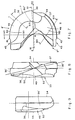
- the component elements of a rotary ball-nose end mill tool is shown in Fig. 1.
- the tool comprises a tool holder 1 having a leading end 2 formed with a substantially rigid support jaw 3 and, juxtaposed with respect thereto a resiliently displaceable clamping jaw 4, the jaws 3 and 4 defining between them an insert receiving slot 5.
- a replaceable cutting insert 6 has a cutting portion 7 and an integrally formed body portion 8 adapted to be received in the slot 5 and clamped therein by clamping screw 9 having a head portion 10 and a cylindrical portion 11 with a screw thread portion 12, at the end thereof remote from the head portion 10.
- the support jaw 3 is formed with an insert supporting seat 3' having a jaw support surface 13 and a pair of jaw abutment walls 15, 16 (Fig. 3) diverging from a jaw abutment apex 17 adjacent a leading end 18 of the support jaw 13 and forming thereby a prismatic shoulder for positioning the insert in radial and axial direction.
- the jaw abutment wall 15 is longer than the jaw abutment wall 16 and intersects a longitudinal axis A of the tool.
- the clamping jaw 4 has a jaw clamping surface 14 juxtaposed with respect to the jaw support surface 13.
- the jaw clamping surface 14 is of a prismatic, concave shape (Figs.
- the jaws 3 and 4 are formed with aligned screw bores 23 and 24 for receiving therein the clamping screw 9.
- the screw bore 23 is formed in the support jaw 3 and is internally threaded being adapted to cooperate with the screw thread portion 12.
- the screw bore 24 is formed in the clamping jaw 4 and is countersunk with an outwardly tapering portion 26 having a maximal diameter greater than a maximal cross-sectional dimension of the screw head 10 and a cylindrical portion 27 adapted to freely receive the screw cylindrical portion 11.
- the tapering portion 26 has a bore clamping raised portion 28 which is innermost with respect to a clamping jaw leading end.
- the screw bores 23 and 24 are slightly inclined towards the leading end 2 of the tool holder.
- the clamping screw 9 is provided with a snap ring 30 adapted to be received in a groove 31 formed in the screw cylindrical portion 11 so that a distance between the screw head 10 and the snap ring 30 is greater than a height of the cylindrical portion 27 of the screw bore 24.
- the cutting insert 6 has a prismatic shape and is shown in Figs. 7, 8, 9 and 10.
- a leading end 8' of the insert body portion 8 has a part disc shape and a terminal end 8'' of the insert body 8 is of a horseshoe-like shape.
- the insert body portion 8 has a top surface 33 and a bottom surface 34, the insert cutting portion 7 being located along a periphery of the insert 6.
- the insert cutting portion 7 is designed so as to provide for cutting along cutting edges 36 and 37 of a substantially helical shape and located on a true spherical surface allowing thereby for machining of a workpiece surface in accordance with computer instructions.
- the spherical surface segments are schematically designated by I and II (Fig. 7) and are disposed on two sides of the longitudinal axis A of the insert, the spherical surface having its center O on the longitudinal axis A.
- the cutting edges 36 and 37 are located respectively adjacent either top surface 33 or bottom surface 34 of the insert body 8 thus constituting respective top and bottom cutting edges 36 and 37 and are defined between respective chip forming rake surface 46 and 47 and relief flank surfaces 35' and 35''.
- Each cutting edge 36, 37 extends from respective cutting edge front extremity 38, 39 disposed at a front end 40 of the cutting portion 7 adjacent the longitudinal axis A to a respective cutting edge trailing extremity 41, 42 disposed at a lateral end 43 of the cutting portion 7.
- the top cutting edge from extremity 38 is substantially closer to the longitudinal axis A of the insert than the bottom cutting edge front extremity 39 and has a configuration enabling the top cutting edge 36 to cut a workpiece in a central cutting area.
- Portions of the top surface 33 and bottom surface 34 adjacent, respectively, the top and bottom cutting edges 36 and 37 constitute the chip forming rake surfaces 46 and 47 (Figs. 7, 10) of the cutting portion 7 of the insert.
- a rake angle ⁇ is preferably positive and varies along the cutting edge 36 from its small value ⁇ 1 at the front end 40 of the cutting portion 7 to a greater value ⁇ 2 at the lateral end 43 of the cutting portion 7 (Figs. 11 and 12).
- the relief flank surfaces 35' and 35'' adjacent the cutting edge 36 and 37 are formed so as to provide a constant relief from an internal spherical surface of a workpiece during rotation of the tool.
- a three dimensional cutting geometry is provided around the cutting edges enabling to improve chip formation in a broad range of cutting speeds and to strengthen a cutting wedge W adjacent the cutting edges, which is particularly important for a central cutting area working under conditions of zero speed and high friction forces.
- the insert body portion 8 to be positioned in the insert supporting seat 3' of the support jaw 3 and clamped thereto by the clamping jaw 4 has an insert support surface 51 (Fig. 10) formed in the insert bottom surface 34 and adapted to be supported by the jaw support surface 13 and an insert clamping surface 49 formed in the insert top surface 33 and being of a convex shape corresponding to the concave shape of the jaw clamping surface 14.
- the insert clamping surface 49 consists of two mutually inclined insert clamping portions 50 merging along a line 50', diverging in the direction away from the front end 40 of the cutting portion and slanted with respect to the insert support surface at angles ⁇ 1 and ⁇ 2 (Figs.
- the insert clamping portions 50 slope downwardly towards the insert support surface 51 in the direction of the front end 40 of the cutting portion 7 in a manner corresponding to that of the jaw clamping surface portions 20 and 21.
- the insert body portion 8 seen better in Figs. 10 and 17, is formed with a concave recess 52 diverging outwardly from a recess apex 52' disposed adjacent the front end 40 of the insert cutting portion 7 and having an insert apical abutting portion 55 and side walls 53 and 54 recessed with respect to projecting side abutting portions 56 and 57.
- the recess 52 is formed with a notch 58 having a stepped configuration and formed adjacent the insert support surface 51 so that its wall constitutes the insert apical abutting portion 55.
- the insert recess 52 and, in particular, its abutting portions are of an appropriate asymmetric design with respect to the axis A and the insert apical abutting portion 55 is located eccentrically with respect to the center O of the spherical surface.
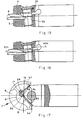
- the clamping screw 9 is inserted into the screw bores 24 and 23 of the respective clamping jaw 4 and support jaw 3 of the tool holder 1 (Fig. 2) so that the screw thread portion 12 engages the internally threaded screw bore 23 and the snap ring 30 is placed in the groove 31 of the clamping screw cylindrical portion 11.
- the resilient clamping jaw 4 Upon the complete insertion of the screw thread portion 12 in the threaded screw bore 23 and consequent bearing of the clamping screw head 10 against the clamping raised portion 28 of the countersunk screw bore 24, the resilient clamping jaw 4 is displaced so as to clamp the insert body portion 8 to support jaw 3 (Fig. 16). Due to the wedge configuration of the insert clamping surface 49 and the jaw clamping surface 14 the latter biases the insert into abutment against the insert supporting seat so that an effective clamping of the insert in its position is thereby achieved.
- the clamping screw 9 is released and slightly screwed outwardly so as to cause the snap ring 30 to bias the clamping jaw 4 away from the insert clamping surface 49 thereby widening the insert receiving slot 5 rendering it ready for removing and replacing the insert.
- the cutting tool according to the present invention may be used with inserts of different types and can have features different from those shown in the above described drawings.
- the clamping jaw may be formed as a separate part rather than being formed integrally with the tool holder.
- the jaw and the insert support surfaces may be curved, e.g. concave or convex.
- the jaw clamping surface may have a convex configuration with the insert clamping surface being consequently concave.
- the areas of contact of the insert recess with the jaw abutment surfaces may be at locations different from those described above, e.g. disposed symmetrically with respect to a longitudinal axis of the tool, depending on a specific configuration of the insert cutting portion.
Landscapes
- Engineering & Computer Science (AREA)
- Mechanical Engineering (AREA)
- Cutting Tools, Boring Holders, And Turrets (AREA)
- Milling Processes (AREA)
- Surgical Instruments (AREA)
Applications Claiming Priority (2)
| Application Number | Priority Date | Filing Date | Title |
|---|---|---|---|
| IL10699993A IL106999A (en) | 1993-09-13 | 1993-09-13 | Cutting tool |
| IL10699993 | 1993-09-13 |
Publications (2)
| Publication Number | Publication Date |
|---|---|
| EP0642864A1 EP0642864A1 (en) | 1995-03-15 |
| EP0642864B1 true EP0642864B1 (en) | 1999-02-03 |
Family
ID=11065269
Family Applications (1)
| Application Number | Title | Priority Date | Filing Date |
|---|---|---|---|
| EP94114323A Expired - Lifetime EP0642864B1 (en) | 1993-09-13 | 1994-09-12 | A cutting tool |
Country Status (12)
| Country | Link |
|---|---|
| US (1) | US5580194A (xx) |
| EP (1) | EP0642864B1 (xx) |
| JP (1) | JP3827246B2 (xx) |
| KR (1) | KR100314926B1 (xx) |
| AU (1) | AU670005B2 (xx) |
| BR (1) | BR9403520A (xx) |
| CA (1) | CA2131779C (xx) |
| DE (1) | DE69416365T2 (xx) |
| ES (1) | ES2126688T3 (xx) |
| IL (1) | IL106999A (xx) |
| SG (1) | SG48180A1 (xx) |
| ZA (1) | ZA947055B (xx) |
Families Citing this family (32)
| Publication number | Priority date | Publication date | Assignee | Title |
|---|---|---|---|---|
| IL111976A (en) * | 1994-12-14 | 1997-11-20 | Iscar Ltd | Parting or grooving insert |
| US6158927A (en) * | 1996-06-17 | 2000-12-12 | Cole Carbide Industries, Inc. | Milling cutter |
| US5782589A (en) * | 1996-06-17 | 1998-07-21 | Cole; John M. | Milling cutter |
| DE19624342C1 (de) * | 1996-06-19 | 1997-12-11 | Walter Ag | Schneidplatte und Fräser, insbesondere Kugelstirnfräser oder Kopierfräser |
| SE507542C2 (sv) * | 1996-12-04 | 1998-06-22 | Seco Tools Ab | Fräsverktyg samt skärdel till verktyget |
| IT1288262B1 (it) * | 1996-12-13 | 1998-09-11 | Livio Mina | Fresa bitagliente monoinserto ad elevata robustezza e precisione |
| DE19730665A1 (de) * | 1997-07-17 | 1999-01-21 | Fischer Artur Werke Gmbh | Bohrer |
| IL124328A (en) | 1998-05-05 | 2003-12-10 | Iscar Ltd | Cutting tool assembly and cutting insert therefor |
| JP2000141118A (ja) * | 1998-09-11 | 2000-05-23 | Sumitomo Electric Ind Ltd | ボ―ルエンドミル |
| EP1020246A1 (en) * | 1999-01-12 | 2000-07-19 | International Minicut Inc. | Cutting tool |
| JP4558884B2 (ja) * | 2000-03-31 | 2010-10-06 | 京セラ株式会社 | ドリル用スローアウェイチップおよびドリル |
| MXPA03005423A (es) | 2000-12-18 | 2005-07-01 | Cardemon Inc | Metodo y aparato de ajuste para una herramienta de perforacion. |
| SE0103752L (sv) * | 2001-11-13 | 2003-05-14 | Sandvik Ab | Roterbart verktyg för spånavskiljande bearbetning jämte skärdel härtill |
| US7234902B2 (en) * | 2003-10-27 | 2007-06-26 | Stojan Stojanovski | Milling tool holder with camming plug |
| US7044695B2 (en) * | 2004-07-02 | 2006-05-16 | Stojan Stojanovski | Milling tool |
| AT7667U1 (de) * | 2004-02-16 | 2005-07-25 | Ceratizit Austria Gmbh | Hochgeschwindigkeitsfräser |
| US20090047077A1 (en) * | 2007-08-13 | 2009-02-19 | Billy Fielder | Tool Holder and Method for Machining Apparatus |
| JP2009142952A (ja) * | 2007-12-17 | 2009-07-02 | Tungaloy Corp | スローアウェイチップ、クランプ機構、およびスローアウェイ式回転工具 |
| KR101064639B1 (ko) * | 2009-02-23 | 2011-09-15 | 대구텍 유한회사 | 절삭 인서트 및 이를 포함하는 절삭 툴 |
| CN102781613A (zh) * | 2010-03-10 | 2012-11-14 | 株式会社钨钛合金 | 紧固辅助部件以及具有该紧固辅助部件的切削工具 |
| IL208253A (en) * | 2010-09-19 | 2015-01-29 | Iscar Ltd | Milling tools and cutting tool for it |
| JP5060626B2 (ja) * | 2011-03-03 | 2012-10-31 | 日立ツール株式会社 | 刃先交換式ボールエンドミル |
| US8876446B2 (en) | 2012-03-28 | 2014-11-04 | Iscar, Ltd. | Cutting tool having clamping bolt provided with locking portion and cutting insert therefor |
| JP5614511B2 (ja) * | 2012-10-10 | 2014-10-29 | 日立ツール株式会社 | ボールエンドミル及びインサート |
| DE102015106082A1 (de) * | 2014-04-24 | 2015-10-29 | Kennametal India Ltd. | Schneidwerkzeug mit auswechselbarem Schneideinsatz und geneigten Befestigungselementen |
| US9700947B2 (en) | 2014-06-27 | 2017-07-11 | Kennametal Inc. | Ballnose cutting tool and ballnose cutting insert |
| CN108290233B (zh) * | 2016-02-12 | 2019-09-13 | 三菱日立工具株式会社 | 可转位刀片式旋转切削工具及刀片 |
| KR102133164B1 (ko) * | 2016-08-26 | 2020-07-13 | 미츠비시 히타치 쓰루 가부시키가이샤 | 절삭 인서트 및 날끝 교환식 회전 절삭 공구 |
| ES2810673T3 (es) * | 2016-12-23 | 2021-03-09 | Walter Ag | Un inserto de fresa de punta esférica, un cuerpo de herramienta de fresa de punta esférica y una fresa de punta esférica |
| CN111745201B (zh) * | 2019-03-29 | 2023-07-25 | 京瓷株式会社 | 立铣刀 |
| CN111761111B (zh) * | 2019-04-01 | 2023-03-21 | 京瓷株式会社 | 立铣刀 |
| CN116858036B (zh) * | 2023-09-04 | 2023-12-29 | 北京爱思达航天科技有限公司 | 一种超薄轻质型复合材料飞行翼及其制备方法 |
Family Cites Families (11)
| Publication number | Priority date | Publication date | Assignee | Title |
|---|---|---|---|---|
| US3027786A (en) * | 1959-11-12 | 1962-04-03 | Viking Tool Company | Boring bars having indexible and disposable cutter inserts |
| DE2941179B1 (de) * | 1979-10-11 | 1981-05-21 | Mapal Fabrik für Präzisionswerkzeuge Kress KG, 7080 Aalen | Zer?kzeug |
| DE3022104C2 (de) * | 1980-06-12 | 1982-08-19 | Mapal Fabrik für Präzisionswerkzeuge Dr.Kress KG, 7080 Aalen | Zerspanungswerkzeug mit Wendeplatte |
| US4334446A (en) * | 1980-07-07 | 1982-06-15 | Approved Performance Tooling, Inc. | Cutting tool and holder therefor |
| DE3030442A1 (de) * | 1980-08-12 | 1982-02-18 | Walter Kieninger KG, 7630 Lahr | Fraeswerkzeug zum fraesen von rillen, insbesondere kugelbahnen homokinetischer gelenke |
| DE3247138C2 (de) * | 1982-12-20 | 1985-04-11 | Gühring, Gottlieb, 7470 Albstadt | Kugelbahnfräser |
| SE450351B (sv) * | 1983-01-18 | 1987-06-22 | Sandvik Ab | Skerverktyg och sker for spanavskiljande bearbetning |
| EP0123887A3 (en) * | 1983-04-29 | 1985-04-17 | NOUVA CA.ME.S. S.p.A. | Device for fixing the cutting insert to the support in a sectional milling cutter |
| US4645383A (en) * | 1985-05-22 | 1987-02-24 | Lindsay Harold W | End milling cutter and method of making same |
| DE3529620A1 (de) * | 1985-08-19 | 1987-02-19 | Kieninger Walter Gmbh | Schneidplatte |
| US5064316A (en) * | 1990-09-26 | 1991-11-12 | Stojan Stojanovski | Ball nose milling tool |
-
1993
- 1993-09-13 IL IL10699993A patent/IL106999A/xx not_active IP Right Cessation
-
1994
- 1994-09-09 AU AU72911/94A patent/AU670005B2/en not_active Ceased
- 1994-09-09 CA CA002131779A patent/CA2131779C/en not_active Expired - Fee Related
- 1994-09-12 SG SG1996007676A patent/SG48180A1/en unknown
- 1994-09-12 BR BR9403520A patent/BR9403520A/pt not_active IP Right Cessation
- 1994-09-12 DE DE69416365T patent/DE69416365T2/de not_active Expired - Lifetime
- 1994-09-12 EP EP94114323A patent/EP0642864B1/en not_active Expired - Lifetime
- 1994-09-12 ES ES94114323T patent/ES2126688T3/es not_active Expired - Lifetime
- 1994-09-13 US US08/304,986 patent/US5580194A/en not_active Expired - Lifetime
- 1994-09-13 JP JP24340094A patent/JP3827246B2/ja not_active Expired - Fee Related
- 1994-09-13 ZA ZA947055A patent/ZA947055B/xx unknown
- 1994-09-13 KR KR1019940023001A patent/KR100314926B1/ko not_active IP Right Cessation
Also Published As
| Publication number | Publication date |
|---|---|
| CA2131779A1 (en) | 1995-03-14 |
| ES2126688T3 (es) | 1999-04-01 |
| BR9403520A (pt) | 1995-05-16 |
| KR950008006A (ko) | 1995-04-15 |
| US5580194A (en) | 1996-12-03 |
| DE69416365T2 (de) | 1999-06-10 |
| AU7291194A (en) | 1995-03-23 |
| ZA947055B (en) | 1995-04-26 |
| DE69416365D1 (de) | 1999-03-18 |
| IL106999A0 (en) | 1993-12-28 |
| KR100314926B1 (ko) | 2002-03-13 |
| CA2131779C (en) | 2005-02-01 |
| EP0642864A1 (en) | 1995-03-15 |
| JP3827246B2 (ja) | 2006-09-27 |
| SG48180A1 (en) | 1998-04-17 |
| IL106999A (en) | 1997-02-18 |
| AU670005B2 (en) | 1996-06-27 |
| JPH07164233A (ja) | 1995-06-27 |
Similar Documents
| Publication | Publication Date | Title |
|---|---|---|
| EP0642864B1 (en) | A cutting tool | |
| CA2156519C (en) | A chip cutting tool | |
| US7309193B2 (en) | Indexable insert with corners with different radii | |
| US8066454B2 (en) | Milling tool with cooperating projections and recesses between the cutting insert and the holder | |
| RU2338630C2 (ru) | Режущий инструмент и способ изготовления его державки | |
| EP1328366B1 (en) | Rotatable tool having a replaceable cutting part at the chip removing free end of the tool | |
| EP0935508B1 (en) | Tool for chip removing machining | |
| CA2262655C (en) | Cutting insert | |
| US5383750A (en) | Exchangeable milling cutting inserts | |
| CA1104330A (en) | Clamping mechanism for cutting insert | |
| US4938638A (en) | Milling cutter | |
| WO2005092545A1 (ja) | スローアウェイチップのクランプ機構 | |
| US5863161A (en) | Countersinking tool with removable cutting inserts | |
| EP0179033B1 (en) | Cutting tool | |
| EP3600733B1 (en) | Cutting insert having two peripheral abutment ridges and cutting tool | |
| EP0638385A1 (en) | Cutting tool | |
| CA1260689A (en) | On-edge end-milling insert | |
| JPH10296516A (ja) | スローアウェイチップ | |
| JP3730010B2 (ja) | スローアウェイ式正面フライスおよびスローアウェイチップ | |
| JPH10296515A (ja) | スローアウェイ式切削工具 |
Legal Events
| Date | Code | Title | Description |
|---|---|---|---|
| PUAI | Public reference made under article 153(3) epc to a published international application that has entered the european phase |
Free format text: ORIGINAL CODE: 0009012 |
|
| AK | Designated contracting states |
Kind code of ref document: A1 Designated state(s): DE ES FR GB IT SE |
|
| 17P | Request for examination filed |
Effective date: 19950412 |
|
| 17Q | First examination report despatched |
Effective date: 19961202 |
|
| GRAG | Despatch of communication of intention to grant |
Free format text: ORIGINAL CODE: EPIDOS AGRA |
|
| GRAG | Despatch of communication of intention to grant |
Free format text: ORIGINAL CODE: EPIDOS AGRA |
|
| GRAG | Despatch of communication of intention to grant |
Free format text: ORIGINAL CODE: EPIDOS AGRA |
|
| GRAH | Despatch of communication of intention to grant a patent |
Free format text: ORIGINAL CODE: EPIDOS IGRA |
|
| GRAH | Despatch of communication of intention to grant a patent |
Free format text: ORIGINAL CODE: EPIDOS IGRA |
|
| GRAA | (expected) grant |
Free format text: ORIGINAL CODE: 0009210 |
|
| GRAH | Despatch of communication of intention to grant a patent |
Free format text: ORIGINAL CODE: EPIDOS IGRA |
|
| AK | Designated contracting states |
Kind code of ref document: B1 Designated state(s): DE ES FR GB IT SE |
|
| ITF | It: translation for a ep patent filed |
Owner name: ING. A. GIAMBROCONO & C. S.R.L. |
|
| REF | Corresponds to: |
Ref document number: 69416365 Country of ref document: DE Date of ref document: 19990318 |
|
| ET | Fr: translation filed | ||
| REG | Reference to a national code |
Ref country code: ES Ref legal event code: FG2A Ref document number: 2126688 Country of ref document: ES Kind code of ref document: T3 |
|
| PG25 | Lapsed in a contracting state [announced via postgrant information from national office to epo] |
Ref country code: ES Free format text: LAPSE BECAUSE OF NON-PAYMENT OF DUE FEES Effective date: 19990913 |
|
| PLBE | No opposition filed within time limit |
Free format text: ORIGINAL CODE: 0009261 |
|
| STAA | Information on the status of an ep patent application or granted ep patent |
Free format text: STATUS: NO OPPOSITION FILED WITHIN TIME LIMIT |
|
| 26N | No opposition filed | ||
| REG | Reference to a national code |
Ref country code: GB Ref legal event code: IF02 |
|
| REG | Reference to a national code |
Ref country code: ES Ref legal event code: FD2A Effective date: 20001013 |
|
| REG | Reference to a national code |
Ref country code: HK Ref legal event code: WD Ref document number: 1004204 Country of ref document: HK |
|
| REG | Reference to a national code |
Ref country code: GB Ref legal event code: 732E |
|
| REG | Reference to a national code |
Ref country code: FR Ref legal event code: TP Ref country code: FR Ref legal event code: CD |
|
| PG25 | Lapsed in a contracting state [announced via postgrant information from national office to epo] |
Ref country code: IT Free format text: LAPSE BECAUSE OF NON-PAYMENT OF DUE FEES Effective date: 20090912 |
|
| PGRI | Patent reinstated in contracting state [announced from national office to epo] |
Ref country code: IT Effective date: 20110616 |
|
| PGFP | Annual fee paid to national office [announced via postgrant information from national office to epo] |
Ref country code: SE Payment date: 20120821 Year of fee payment: 19 Ref country code: GB Payment date: 20120817 Year of fee payment: 19 |
|
| PGFP | Annual fee paid to national office [announced via postgrant information from national office to epo] |
Ref country code: FR Payment date: 20120828 Year of fee payment: 19 Ref country code: IT Payment date: 20120905 Year of fee payment: 19 |
|
| PGFP | Annual fee paid to national office [announced via postgrant information from national office to epo] |
Ref country code: DE Payment date: 20130719 Year of fee payment: 20 |
|
| REG | Reference to a national code |
Ref country code: SE Ref legal event code: EUG |
|
| PG25 | Lapsed in a contracting state [announced via postgrant information from national office to epo] |
Ref country code: SE Free format text: LAPSE BECAUSE OF NON-PAYMENT OF DUE FEES Effective date: 20130913 |
|
| GBPC | Gb: european patent ceased through non-payment of renewal fee |
Effective date: 20130912 |
|
| REG | Reference to a national code |
Ref country code: FR Ref legal event code: ST Effective date: 20140530 |
|
| PG25 | Lapsed in a contracting state [announced via postgrant information from national office to epo] |
Ref country code: GB Free format text: LAPSE BECAUSE OF NON-PAYMENT OF DUE FEES Effective date: 20130912 |
|
| PG25 | Lapsed in a contracting state [announced via postgrant information from national office to epo] |
Ref country code: IT Free format text: LAPSE BECAUSE OF NON-PAYMENT OF DUE FEES Effective date: 20130912 Ref country code: FR Free format text: LAPSE BECAUSE OF NON-PAYMENT OF DUE FEES Effective date: 20130930 |
|
| REG | Reference to a national code |
Ref country code: DE Ref legal event code: R071 Ref document number: 69416365 Country of ref document: DE |
|
| PG25 | Lapsed in a contracting state [announced via postgrant information from national office to epo] |
Ref country code: DE Free format text: LAPSE BECAUSE OF EXPIRATION OF PROTECTION Effective date: 20140913 |