EP1020246A1 - Cutting tool - Google Patents
Cutting tool Download PDFInfo
- Publication number
- EP1020246A1 EP1020246A1 EP99300173A EP99300173A EP1020246A1 EP 1020246 A1 EP1020246 A1 EP 1020246A1 EP 99300173 A EP99300173 A EP 99300173A EP 99300173 A EP99300173 A EP 99300173A EP 1020246 A1 EP1020246 A1 EP 1020246A1
- Authority
- EP
- European Patent Office
- Prior art keywords
- ball nose
- cutting
- nose cutting
- insert
- cutting insert
- Prior art date
- Legal status (The legal status is an assumption and is not a legal conclusion. Google has not performed a legal analysis and makes no representation as to the accuracy of the status listed.)
- Withdrawn
Links
Images


Classifications
-
- B—PERFORMING OPERATIONS; TRANSPORTING
- B23—MACHINE TOOLS; METAL-WORKING NOT OTHERWISE PROVIDED FOR
- B23C—MILLING
- B23C5/00—Milling-cutters
- B23C5/02—Milling-cutters characterised by the shape of the cutter
- B23C5/10—Shank-type cutters, i.e. with an integral shaft
- B23C5/1009—Ball nose end mills
- B23C5/1027—Ball nose end mills with one or more removable cutting inserts
- B23C5/1036—Ball nose end mills with one or more removable cutting inserts having a single cutting insert, the cutting edges of which subtend 180 degrees
Definitions
- the present invention is related to a cutting tool and more particularly to a rotary cutting tool assembly.
- Ball nose end mills with carbide ball inserts have been known for a long time. These tools are the backbone of the moulding industries, and are used for machining intricate shapes and cavities.
- the present invention provides a ball nose cutting insert comprising: an elongate body of unitary configuration, said ball nose cutting insert having at least one full ball nose cutting end, wherein said full ball nose cutting end has a cutting edge of continuous spiral fluted configuration.
- the present invention further relates to a rotary cutting tool incorporating such an insert, the insert being fixed into a holding body provided with a slot adapted to securely and non-movably hold the said insert.
- Said full ball nose cutting end of said insert may comprise a cutting face consisting of two radius cutting edges meeting at a center or tip of said full ball nose cutting end by means of a web.
- said cutting face forms a true helical path made of a continuous curve following a spiral shape, helix angles of said radius cutting edges being between 3 and 45 degrees with respect to a longitudinal axis of said ball nose cutting insert in both right and left directions.
- Said ball nose cutting insert may have a solid configuration, and may have two identical reversible full ball nose cutting ends formed on opposite ends of said insert.
- Said radius cutting edges of said cutting faces may be arranged to form a spiral or helical configuration, and cutting faces of said single ball nose cutting insert may be formed by means of a grinding wheel.
- Said ball nose cutting insert may have locating grooves formed near each end of said insert, said locating grooves being provided to firmly seat in corresponding seating faces formed within the said slot of a said holding body.
- Fig. 1 shows a plan view of an insert according to the present invention.
- Fig. 2 shows a top view of Fig. 1.
- Fig. 3 shows a front view of Fig. 1.
- Fig. 4 shows a perspective view of Fig. 1.
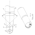
- Fig. 5 shows a perspective dis-assembled view of a complete cutting tool assembly.
- Fig. 6 shows a perspective view of assembled components of Fig. 5.
- Fig. 7 shows a front view of Fig. 6.
- Fig. 8 shows a partial top view of Fig. 6.
- Fig. 9 shows a partial perspective view of Fig. 6.
- Fig. 10 shows a cross-sectional view taken along lines A-A of Fig. 9.
- Fig. 11 shows a cross-sectional view taken along lines B-B of Fig. 9.
- Fig. 12 shows a plan view of the insert according to the present invention.
- Fig. 13 shows a top view of Fig. 9.
- Fig. 14 shows a prior art design.
- Fig. 1 - 6 show a rotary cutting tool assembly 10 including a holder 12 and an insert 14 fixed immovably in the holder 12.
- the insert 14 comprises an elongated body provided on both ends with two full ball end cutting faces 16 having a continuous spiral fluted configuration.
- Each of these cutting faces 16 consists of two radius cutting edges 18 joining at the center with a web 20, thus forming a tip of the respective full ball nose end.
- the cutting edges 18 follow a true helix configuration (see Fig. 3), wherein each cutting face 16 is made of a continuous curve following a spiral configuration without forming any straight faced segment.
- the helix angles of the cutting edges 18 in the insert 14 with respect to a longitudinal axis are between 3° to 45° on both right and left hand directions .
- the helix angle is chosen between 10 and 15° as shown on Fig. 2. Theoretically, it is possible to make the angle wider than 45°, but in this case other considerations such as thickness of the insert come into play.
- the insert 14 is provided with two identical locating set of grooves 22A, 22B and 23A, 23B formed near each ball end cutting face 16.
- the locating set of grooves 22A, 22B, 23 A and 23B are oriented under 45° with respect to the longitudinal axis.
- locating set of grooves 22A and 22B are oriented in the opposite direction with respect to a set of location grooves 23A and 23B.
- the insert 14 has two openings 26 provided for fixing the insert 14 into the holder 12 by means of a specially designed slot 36 formed at one end of the holder 12.
- the slot 36 divides the end of the holder 12 into two symmetrical halves identified as 40 and 42.
- the inner surfaces of halves 40 and 42 have two identical seating faces 24 and 25 better shown on Figs 10 and 11. Each of these seating faces are made under 45° with respect to the longitudinal axis, but are oriented in opposite directions.
- Each of the halves 40 and 42 is provided with a set of openings 28 and 30, wherein the opening 28 has a slightly smaller diameter than opening 30. As it may be seen on Fig. 11, on half 40 the larger opening 30 is closer to the tip than the smaller opening 28, wherein on Fig. 10 it is vice versa.
- insert 14 The fixing of insert 14 into the slot 36 is provided by means of screws 32 and 34. Opening 30 of the half 42 and opening 28 of the half 40 are slightly off center to allow the insert 14 to be pushed against the corresponding seating faces.
- the insert 14 is positioned into the slot 36, then the screw 34 is inserted through the opening 26 of the insert 14 which is placed to correspond with the opening 28 of the half 42 and opening 30 of the half 40. This allows to preliminarily fix the insert inside of the slot 36.
- second screw 32 is inserted into the second opening 26 of the insert 14 which corresponds with the opening 30 of the half 42 and opening 28 of the half 40.
- the holder 12 is made from solid steel and the insert 14 is made from highspeed steel or carbide.
- the fluted configuration of the insert 14 is made by means of a grinding wheel.
Abstract
A rotary cutting tool includes a single ball nose
cutting insert (14) of a generally elongate
configuration. The ball nose cutting insert is fixed
into a holding body (12) provided with a slot (36)
adapted to securely and non-movably hold the insert.
The single ball nose cutting insert has at least one
full ball nose cutting end having a cutting edge (18) of
a continuous spiral fluted configuration. The full ball
nose cutting end comprises a cutting face (16)
consisting of two radius cutting edges meeting at a
center or tip of the full ball nose cutting end by means
of a web (20). The cutting face forms a true helical
path made of a continuous curve following a spiral
shape, and helix angles of the radius cutting edges are
between 3 and 45 degrees with respect to a longitudinal
axis of the ball nose cutting insert in both right and
left directions. The ball nose cutting insert has a
solid configuration and comprises two identical
reversible full ball nose cutting ends formed on
opposite ends of the insert. The radius cutting edges
of the cutting faces are arranged to form a spiral or
helical configuration, and the cutting faces of the
single ball nose cutting insert are formed by means of a
grinding wheel.

Description
- The present invention is related to a cutting tool and more particularly to a rotary cutting tool assembly.
- Ball nose end mills with carbide ball inserts have been known for a long time. These tools are the backbone of the moulding industries, and are used for machining intricate shapes and cavities.
- There are known a few designs of the inserted ball nose end mills. Most of the existing designs have one or two of the following features:
- two separate radius inserts with one insert slightly past the center to achieve a ball end plunge;
- single ball insert with ball on one end only with straight or "0" helix ball cutting edge.
- Viewed from one aspect the present invention provides a ball nose cutting insert comprising:
an elongate body of unitary configuration, said ball nose cutting insert having at least one full ball nose cutting end, wherein said full ball nose cutting end has a cutting edge of continuous spiral fluted configuration. - The present invention further relates to a rotary cutting tool incorporating such an insert, the insert being fixed into a holding body provided with a slot adapted to securely and non-movably hold the said insert.
- Said full ball nose cutting end of said insert may comprise a cutting face consisting of two radius cutting edges meeting at a center or tip of said full ball nose cutting end by means of a web.
- In one form of the present invention, said cutting face forms a true helical path made of a continuous curve following a spiral shape, helix angles of said radius cutting edges being between 3 and 45 degrees with respect to a longitudinal axis of said ball nose cutting insert in both right and left directions. Said ball nose cutting insert may have a solid configuration, and may have two identical reversible full ball nose cutting ends formed on opposite ends of said insert.
- Said radius cutting edges of said cutting faces may be arranged to form a spiral or helical configuration, and cutting faces of said single ball nose cutting insert may be formed by means of a grinding wheel. Said ball nose cutting insert may have locating grooves formed near each end of said insert, said locating grooves being provided to firmly seat in corresponding seating faces formed within the said slot of a said holding body.
- An embodiment of the invention will now be described by way of example and with reference to the accompanying drawings, in which:-
- Fig. 1 shows a plan view of an insert according to the present invention.
- Fig. 2 shows a top view of Fig. 1.
- Fig. 3 shows a front view of Fig. 1.
- Fig. 4 shows a perspective view of Fig. 1.
- Fig. 5 shows a perspective dis-assembled view of a complete cutting tool assembly.
- Fig. 6 shows a perspective view of assembled components of Fig. 5.
- Fig. 7 shows a front view of Fig. 6.
- Fig. 8 shows a partial top view of Fig. 6.
- Fig. 9 shows a partial perspective view of Fig. 6.
- Fig. 10 shows a cross-sectional view taken along lines A-A of Fig. 9.
- Fig. 11 shows a cross-sectional view taken along lines B-B of Fig. 9.
- Fig. 12 shows a plan view of the insert according to the present invention.
- Fig. 13 shows a top view of Fig. 9.
- Fig. 14 shows a prior art design.
- Referring now to drawings, Fig. 1 - 6 show a rotary
cutting tool assembly 10 including aholder 12 and aninsert 14 fixed immovably in theholder 12. Theinsert 14 comprises an elongated body provided on both ends with two full ballend cutting faces 16 having a continuous spiral fluted configuration. Each of thesecutting faces 16 consists of tworadius cutting edges 18 joining at the center with aweb 20, thus forming a tip of the respective full ball nose end. In operation, only onecutting face 16 is used at a given time. Thecutting edges 18 follow a true helix configuration (see Fig. 3), wherein eachcutting face 16 is made of a continuous curve following a spiral configuration without forming any straight faced segment. The helix angles of thecutting edges 18 in theinsert 14 with respect to a longitudinal axis are between 3° to 45° on both right and left hand directions . Preferably but not necessarily, the helix angle is chosen between 10 and 15° as shown on Fig. 2. Theoretically, it is possible to make the angle wider than 45°, but in this case other considerations such as thickness of the insert come into play. - The
insert 14 is provided with two identical locating set ofgrooves end cutting face 16. Preferably, the locating set ofgrooves grooves 22A and 22B are oriented in the opposite direction with respect to a set oflocation grooves 23A and 23B. - The
insert 14 has twoopenings 26 provided for fixing theinsert 14 into theholder 12 by means of a specially designedslot 36 formed at one end of theholder 12. Theslot 36 divides the end of theholder 12 into two symmetrical halves identified as 40 and 42. The inner surfaces ofhalves halves openings half 40 thelarger opening 30 is closer to the tip than thesmaller opening 28, wherein on Fig. 10 it is vice versa. The fixing ofinsert 14 into theslot 36 is provided by means ofscrews Opening 30 of thehalf 42 and opening 28 of thehalf 40 are slightly off center to allow theinsert 14 to be pushed against the corresponding seating faces. To complete the assembly, theinsert 14 is positioned into theslot 36, then thescrew 34 is inserted through theopening 26 of theinsert 14 which is placed to correspond with the opening 28 of thehalf 42 and opening 30 of thehalf 40. This allows to preliminarily fix the insert inside of theslot 36. Then,second screw 32 is inserted into the second opening 26 of theinsert 14 which corresponds with the opening 30 of thehalf 42 and opening 28 of thehalf 40. By tightening thescrew 32, the locating groove 22 B will firmly abut thecorresponding seating face 25 and locating groove 23B will firmly abut the corresponding seating face 24 (see Figs 10-12). Similar procedure will take place when the reversible identical ball end will be used. In this case, locatinggroove 23A will abutcorresponding seating face 24 and locatinggroove 22A will abut thecorresponding seating place 25. Such an arrangement of fixing theinsert 14 inside of theslot 36 allows to provide a highly stable and immovable seating of the insert inside the holder, which is a substantial advantage of the present invention. - Preferably, the
holder 12 is made from solid steel and theinsert 14 is made from highspeed steel or carbide. The fluted configuration of theinsert 14 is made by means of a grinding wheel. - The present embodiment has the following advantages if compared to known designs:
- in side milling applications, known tools with "0" helical teeth (see Fig. 13) have a tendency to chatter and break teeth in view of the fact that in a straight flute with "0" helix end mill application the load on each cutting edge builds up almost instantaneously, thus causing deflection, springbacks and chatter. At the same time, when helical fluted edges of the present invention are used, the chip load is evenly distributed along the entire flute length in the progressive sliding action, and hence provides a smoother cutting;
- the configuration of the cutting face consisting of two radius cutting edges
meeting at the center or tip allows to achieve a center cutting application wherein the tool can be
plunged straight into a metal just like a drill to make a hole. In this case, the
web 20 at the center make thecutting face 16 continuous at the tip, and when the tool is plunged into a metal it will be able to cut at the bottom. Without this new configuration of the cutting face, it is not possible to plunge-cut, which is a very advantageous feature of the present invention; - the arrangement of the present invention allows a smoother and more efficient cutting action which was not possible with the known "0" helix inserts. The spiral fluted ball end insert of the present invention enables the tool to cut smoothly resulting in better cutting and higher productivity;
- the presence of the two reversible ball cutting ends in one solid single insert allows cost reduction and substantially decreased machine downtime.
Claims (11)
- A ball nose cutting insert (14) comprising: an elongate body of unitary configuration, said ball nose cutting insert having at least one full ball nose cutting end, wherein said full ball nose cutting end has a cutting edge (18) of continuous spiral fluted configuration.
- A ball nose cutting insert according to claim 1, which is adapted to be fixed into a holding body (12) of a rotary cutting tool, said holding body being provided with a slot (36) adapted to securely and non-movably hold said insert.
- A ball nose cutting insert according to claim 1 or 2, wherein said full ball nose cutting end comprises a cutting face (16) consisting of two radius cutting edges (18) meeting at a center or tip of said full ball nose cutting end by means of a web (20).
- A ball nose cutting insert according to claim 3, wherein said cutting face (16) forms a true helical path made of a continuous curve following a spiral shape.
- A ball nose cutting insert according to claim 3 or 4, wherein helix angles of said radius cutting edges (18) are between 3 and 45 degrees with respect to a longitudinal axis of said ball nose cutting insert in both right and left directions.
- A ball nose cutting insert according to any preceding claim, wherein said ball nose cutting insert has a solid configuration.
- A ball nose cutting insert according to any preceding claim, wherein said single ball nose cutting insert has two identical reversible said full ball nose cutting ends formed on opposite ends of said insert.
- A ball nose cutting insert according to claim 7, wherein said radius cutting edges (18) of the said cutting ends are arranged to form a spiral or helical configuration.
- A ball nose cutting insert according to claim 7 or 8, wherein cutting faces (16) of said single ball nose cutting insert (14) are formed by means of a grinding wheel.
- A ball nose cutting insert according to claim 2 and any of claims 7 to 9, wherein said ball nose cutting insert has locating grooves (22A etc) formed near each end of said insert, said locating grooves being arranged to firmly seat in corresponding seating faces (24,25) formed within said slot (36) of said holding body (12).
- A rotary cutting tool assembly comprising a ball nose cutting insert as claimed in any of claims 1 to 10, said ball nose cutting insert being fixed into a holding body (12) provided with a slot (36) adapted to securely and non-movably hold said insert.
Priority Applications (1)
| Application Number | Priority Date | Filing Date | Title |
|---|---|---|---|
| EP99300173A EP1020246A1 (en) | 1999-01-12 | 1999-01-12 | Cutting tool |
Applications Claiming Priority (1)
| Application Number | Priority Date | Filing Date | Title |
|---|---|---|---|
| EP99300173A EP1020246A1 (en) | 1999-01-12 | 1999-01-12 | Cutting tool |
Publications (1)
| Publication Number | Publication Date |
|---|---|
| EP1020246A1 true EP1020246A1 (en) | 2000-07-19 |
Family
ID=8241180
Family Applications (1)
| Application Number | Title | Priority Date | Filing Date |
|---|---|---|---|
| EP99300173A Withdrawn EP1020246A1 (en) | 1999-01-12 | 1999-01-12 | Cutting tool |
Country Status (1)
| Country | Link |
|---|---|
| EP (1) | EP1020246A1 (en) |
Citations (3)
| Publication number | Priority date | Publication date | Assignee | Title |
|---|---|---|---|---|
| EP0096147A1 (en) * | 1982-06-10 | 1983-12-21 | Seco Tools Ab | Cutting tool and cutting insert therefor |
| DE3529620A1 (en) * | 1985-08-19 | 1987-02-19 | Kieninger Walter Gmbh | CUTTING INSERT |
| EP0642864A1 (en) * | 1993-09-13 | 1995-03-15 | Iscar Limited | A cutting tool |
-
1999
- 1999-01-12 EP EP99300173A patent/EP1020246A1/en not_active Withdrawn
Patent Citations (3)
| Publication number | Priority date | Publication date | Assignee | Title |
|---|---|---|---|---|
| EP0096147A1 (en) * | 1982-06-10 | 1983-12-21 | Seco Tools Ab | Cutting tool and cutting insert therefor |
| DE3529620A1 (en) * | 1985-08-19 | 1987-02-19 | Kieninger Walter Gmbh | CUTTING INSERT |
| EP0642864A1 (en) * | 1993-09-13 | 1995-03-15 | Iscar Limited | A cutting tool |
Similar Documents
| Publication | Publication Date | Title |
|---|---|---|
| US5915888A (en) | Rotary cutting tool assembly | |
| US7997836B2 (en) | Indexable type cutting tool | |
| US8066454B2 (en) | Milling tool with cooperating projections and recesses between the cutting insert and the holder | |
| KR100776555B1 (en) | Drilling tool and indexable drill bit | |
| US7001114B2 (en) | Device for chip removing machining | |
| US7309193B2 (en) | Indexable insert with corners with different radii | |
| EP0876868B1 (en) | Drill | |
| US7390151B2 (en) | Helical cutter head and helical cutting blade for use therewith | |
| RU2547365C2 (en) | Adjustable drill with mechanical fastening of diamond inserts | |
| EP2334459B1 (en) | Adjustable indexable drill and modular system and holder | |
| EP0841115A1 (en) | Elongated drill with replaceable cutting inserts | |
| HU214993B (en) | Exchangeable hard metal cutting insert | |
| JP2004527391A (en) | A rotary tool with a replaceable cutter head at the free end of the cutting tool | |
| KR20130052561A (en) | Cutting tool | |
| CZ20012280A3 (en) | Tool and cutting head for chip-forming cutting | |
| KR101081786B1 (en) | Milling cutter for rotary cutting machining | |
| US20100034607A1 (en) | Adjustable indexable drill and modular system and holder | |
| US4768901A (en) | Drill having two or more cutting edges comprising exchangeable cutting members | |
| KR20080009330A (en) | Helical cutting insert with axial clearance slash | |
| US7641423B2 (en) | Apparatus for chip removing machining | |
| US5993119A (en) | Drill having cooling channel and chip flutes | |
| KR101276401B1 (en) | End milling cutter | |
| EP1020246A1 (en) | Cutting tool | |
| JP4952068B2 (en) | Throw-away rotary tool | |
| WO2006036041A1 (en) | Indexable type cutting tool |
Legal Events
| Date | Code | Title | Description |
|---|---|---|---|
| PUAI | Public reference made under article 153(3) epc to a published international application that has entered the european phase |
Free format text: ORIGINAL CODE: 0009012 |
|
| 17P | Request for examination filed |
Effective date: 19991209 |
|
| AK | Designated contracting states |
Kind code of ref document: A1 Designated state(s): DE ES FR GB IT |
|
| AX | Request for extension of the european patent |
Free format text: AL;LT;LV;MK;RO;SI |
|
| AKX | Designation fees paid |
Free format text: DE ES FR GB IT |
|
| 17Q | First examination report despatched |
Effective date: 20010724 |
|
| STAA | Information on the status of an ep patent application or granted ep patent |
Free format text: STATUS: THE APPLICATION IS DEEMED TO BE WITHDRAWN |
|
| 18D | Application deemed to be withdrawn |
Effective date: 20030130 |