EP0641985B1 - Wärmetauschertank mit Verstärkungsriegel - Google Patents
Wärmetauschertank mit Verstärkungsriegel Download PDFInfo
- Publication number
- EP0641985B1 EP0641985B1 EP94306280A EP94306280A EP0641985B1 EP 0641985 B1 EP0641985 B1 EP 0641985B1 EP 94306280 A EP94306280 A EP 94306280A EP 94306280 A EP94306280 A EP 94306280A EP 0641985 B1 EP0641985 B1 EP 0641985B1
- Authority
- EP
- European Patent Office
- Prior art keywords
- tank
- heat exchanger
- tie bar
- pockets
- head portions
- Prior art date
- Legal status (The legal status is an assumption and is not a legal conclusion. Google has not performed a legal analysis and makes no representation as to the accuracy of the status listed.)
- Expired - Lifetime
Links
- 238000005728 strengthening Methods 0.000 claims description 10
- 230000007423 decrease Effects 0.000 claims description 9
- 238000000034 method Methods 0.000 claims description 7
- 238000003466 welding Methods 0.000 claims description 7
- 230000003247 decreasing effect Effects 0.000 claims description 2
- 239000000463 material Substances 0.000 description 4
- 238000005266 casting Methods 0.000 description 3
- 230000000694 effects Effects 0.000 description 3
- 229910052751 metal Inorganic materials 0.000 description 3
- 239000002184 metal Substances 0.000 description 3
- 239000004033 plastic Substances 0.000 description 3
- 229920003023 plastic Polymers 0.000 description 3
- 238000003780 insertion Methods 0.000 description 2
- 230000037431 insertion Effects 0.000 description 2
- 238000004519 manufacturing process Methods 0.000 description 2
- 239000004677 Nylon Substances 0.000 description 1
- 239000000956 alloy Substances 0.000 description 1
- 229910045601 alloy Inorganic materials 0.000 description 1
- 239000004411 aluminium Substances 0.000 description 1
- 229910052782 aluminium Inorganic materials 0.000 description 1
- XAGFODPZIPBFFR-UHFFFAOYSA-N aluminium Chemical compound [Al] XAGFODPZIPBFFR-UHFFFAOYSA-N 0.000 description 1
- 230000015572 biosynthetic process Effects 0.000 description 1
- 150000002739 metals Chemical class 0.000 description 1
- 229920001778 nylon Polymers 0.000 description 1
- 230000002787 reinforcement Effects 0.000 description 1
- 230000003014 reinforcing effect Effects 0.000 description 1
- 125000006850 spacer group Chemical group 0.000 description 1
Images


Classifications
-
- F—MECHANICAL ENGINEERING; LIGHTING; HEATING; WEAPONS; BLASTING
- F28—HEAT EXCHANGE IN GENERAL
- F28F—DETAILS OF HEAT-EXCHANGE AND HEAT-TRANSFER APPARATUS, OF GENERAL APPLICATION
- F28F9/00—Casings; Header boxes; Auxiliary supports for elements; Auxiliary members within casings
- F28F9/02—Header boxes; End plates
- F28F9/0219—Arrangements for sealing end plates into casing or header box; Header box sub-elements
- F28F9/0224—Header boxes formed by sealing end plates into covers
-
- F—MECHANICAL ENGINEERING; LIGHTING; HEATING; WEAPONS; BLASTING
- F28—HEAT EXCHANGE IN GENERAL
- F28F—DETAILS OF HEAT-EXCHANGE AND HEAT-TRANSFER APPARATUS, OF GENERAL APPLICATION
- F28F9/00—Casings; Header boxes; Auxiliary supports for elements; Auxiliary members within casings
- F28F9/02—Header boxes; End plates
- F28F2009/0285—Other particular headers or end plates
- F28F2009/029—Other particular headers or end plates with increasing or decreasing cross-section, e.g. having conical shape
-
- F—MECHANICAL ENGINEERING; LIGHTING; HEATING; WEAPONS; BLASTING
- F28—HEAT EXCHANGE IN GENERAL
- F28F—DETAILS OF HEAT-EXCHANGE AND HEAT-TRANSFER APPARATUS, OF GENERAL APPLICATION
- F28F2225/00—Reinforcing means
- F28F2225/08—Reinforcing means for header boxes
-
- Y—GENERAL TAGGING OF NEW TECHNOLOGICAL DEVELOPMENTS; GENERAL TAGGING OF CROSS-SECTIONAL TECHNOLOGIES SPANNING OVER SEVERAL SECTIONS OF THE IPC; TECHNICAL SUBJECTS COVERED BY FORMER USPC CROSS-REFERENCE ART COLLECTIONS [XRACs] AND DIGESTS
- Y10—TECHNICAL SUBJECTS COVERED BY FORMER USPC
- Y10S—TECHNICAL SUBJECTS COVERED BY FORMER USPC CROSS-REFERENCE ART COLLECTIONS [XRACs] AND DIGESTS
- Y10S165/00—Heat exchange
- Y10S165/906—Reinforcement
Definitions
- the present invention relates to a heat exchanger manifold tank with a tie bar and to a method of assembly of a heat exchanger manifold.
- Heat exchangers of the type which are employed in automobiles, for example, as charged air coolers for turbochargers, comprise a manifold in the form of separate tank and header parts which are joined together to define a manifold housing. This housing is connected to a large number of heat exchange tubes through which air to be cooled is passed. The heat exchange tubes are connected at end portions thereof to the header part.
- Such manifolds are subject to expansions arising from elevated temperatures and pressures, which render them liable to failure.
- the tank parts are reinforced to resist this expansion by the provision of increased wall thickness, the addition of internal and/or external ribbing, or the addition of internal tie bars which extend between inner walls of the tank, and which are cast with the tank or are welded in position.
- An increase in the header material gauge may also be employed as a means of reinforcement.
- An object of the invention is to provide a heat exchanger tank which overcomes the problems discussed above.
- a heat exchanger tank for connection to a header part to form a heat exchanger manifold, said tank comprising an elongate trough-shaped body and plural strengthening tie bars, the body having opposed side walls defining opposed pockets for receiving therein portions of said tie bars so that said tie bars extend between said side walls, and have portions adapted to engage in said pockets characterised in that said pockets being generally wedge-shaped and of a dimension which decreases in a direction generally perpendicular to the direction between the opposed side walls, towards a base of the pocket.
- tie bar which is insertable into pockets on the tank overcomes the problems of formation of tie bars which are cast in position.
- the arrangement of head portions of wedge-shaped section, and correspondingly-shaped pockets in the tank side walls means that the tie bar can be easily located, since on fitting, a relatively small end of the head portion (ie the narrow end of the wedge) is required to be fitted into a relatively larger pocket opening.
- the tie bars are essentially self-locating.
- the wedge shape also allows the tie bar to be held very firmly in the pockets.
- the tie bars are preferably subsequently additionally welded in place, the wedge-shape arrangement ensures a significant degree of self-retention, increasing their strengthening effect.
- the head portions are of generally semicircular form viewed in the direction of elongate extent of the body.
- the head portions have a generally straight edge region constituting the straight edge of the semicircle, and a curved semicircular edge region, and decrease in thickness (as measured in the direction of elongate extent of the tie bar body) from the straight region to a portion of the semicircular region remote therefrom.
- the semicircular shape provides a large surface area for the head portions, and hence for the degree of contact with a correspondingly shaped pocket in a tank part, thereby maximising the degree of self-retention, and increasing the strengthening effect.
- the side walls of the tank define pockets of corresponding wedge-shaped form to the form of the tie bar head portions between a respective inwardly facing wall portion and a lip which is disposed inwardly of said wall portion and which is abutted by a region of the body portion of the tie bar adjacent the head portion when the tie bar is fitted in place.
- This lip functions as a load-bearing lip.
- the tie bar is provided at opposite ends thereof with projecting lugs which extend beyond the semicircular wedge-shape of the head portions. These are to be received within recesses defined within the side walls of the tank.
- the tank has a rim at which the tank is engageable with a header part to form a manifold housing, the rim defining the notches for receiving the projecting lugs, which notches extend through the entire tank wall thickness.
- This arrangement of projecting lugs and receiving notches means that when the tank and header parts are assembled, the weld material of the weld employed to join the tank and header parts contacts the projecting lugs so as to weld the tie bar in position, and obviates the need for a separate weld step for securing the tie bar.
- the projecting lugs are omitted and the tie bar is fitted into the tank with the head portions engaged in the pockets, and is welded into place with a weld joint at an exposed portion of the junction between the head portion and the tank side wall.
- a method of assembly of a heat exchanger manifold comprising the steps of a) providing a heat exchanger tank in accordance with the first aspect of the invention, and said header part, wherein said pockets having notches which extend through the side walls, said portions by enlarged head portions of a generally wedge-shaped section of a dimension which decreases in a direction generally perpendicular to the elongate extent of the tie bar body, and projecting lugs which project from opposite ends of the head portions; b) fitting the tie bar to the tank body so that the said portions are received, in the pockets and, said enlarged head portions are received narrow end first so that the projecting lugs are received within the sidewall notches, c) welding a header part to free edges of the side wall so that the weld joint contacts the projecting lugs through the notch to thereby also weld the tie bar in place.
- a method of assembly of a heat exchanger manifold comprising the steps of a) providing a heat exchanger tank in accordance with the first aspect of the invention, and said header part, wherein said portions are enlarged head portions of a generally wedge-shaped section of a dimension which decreases in a direction generally perpendicular to the elongate extent of the tie bar body; b) fitting the tie bar to the tank body so that the portions are received, narrow end first, in the apertures; c) welding the tie bar in position by forming a weld joint at an exposed portion of the junction between the tie bar head portions and the tank side wall; and d) welding a header part to free edges of the side wall.
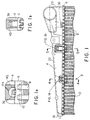
- Figure 1 shows in side view a part of a heat exchanger generally desigated 2.
- the heat exchanger comprises a tank 4 secured to a header 6.
- the header 6 is provided with a plurality of heat exchange tubes 8, end portions 10 of which extend through apertures formed in the header part 6.
- Inserts 12, comprising bands of sheet metal which are curved or corrugated are located in the spaces between the heat exchange tubes 8, so as to be in thermal contact with the tubes 8.
- the tank 4 comprises an elongate generally channel-shaped or trough-shaped half-shell having opposed side walls 14,16 (best seen in Figures 4 and 5), opposed end walls 18,20 and a wall 22 referred to below as a base wall since it forms a base of the trough, although in the illustrated embodiment for use as a charged air cooler this wall is generally uppermost.
- the header 6 comprises an elongate channel-shaped member having a base 24 and upstanding longitudinal side walls 26,28. Outwardly facing edge regions 30,32 of the tank side walls are received within the channel of the header 6, so that inwardly facing edge regions 31,33 of the side walls 26,28 engage the edge regions 30,32.
- the tank and header parts are joined by a weld joint 34.
- tie bars 36,38 which extend laterally across the tank. This is best seen in the view of Figure 7 which is a view into the open channel of the tank with the tie bars fitted in place, before connection of the header.
- the tie bars 36 are disposed at locations adjacent the tank-header weld joint, whilst the tie bars 38 are disposed at locations spaced from this joint.
- the tank of Figure 1 employs two tie bars of the type denoted 36 and a single tie bar of the type denoted 38, the number and location of each of these forms could be varied for particular applications of the tank.
- a tie bar 36 comprises a straight, elongate body in the form of a shank or shaft 37 having at opposite ends thereof enlarged head portions 40.
- the shank cross-section which is approximately square in the illustrated embodiment may take a variety of other forms. It is important that the dimensions are sufficient so that the tie bars have the requisite strength to provide the required strengthening of the tank.
- the head portions are of plate-like generally semicircular form, having a straight edge region 41 and curved semicircular edge region 42. These head portions 40 are in section generally wedge-shaped, of decreasing thickness (measured in the direction of the elongate shaft 37) from the straight edge region 41 to a portion of the curved edge region 42 remote therefrom, ie in the direction of insertion in the pockets as discussed below.
- At opposite extremities of the tie bar 36 there are disposed short lugs or projections 43.
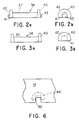
- the tie bar 36 is fitted within pockets 44 provided on the opposed side walls 14,16 which are shaped to receive the head portions 40. These pockets are preferably formed in regions of increased wall thickness 45.
- the pockets 44 comprise semicircular wedge-shaped recesses shaped to receive the head portion 40, which are defined between an external wall portion 46, and a load bearing lip 48.
- a receiving notch 50 extends through the walls, as seen in Figure 6, into which the lugs or projections 43 of the tie bar 36 are received.
- the tie bar 36 is fitted to the tank by arranging the tie bar 36 across the tank at the location of opposed pockets 44 and fitting this to the tank so that the wedge-shaped head portions 40 enter into the pockets 44, narrow end first.
- the header is then fitted over the open side of the tank part, and the weld joint 34 is created.
- the creation of the weld joint also serves to hold the tie bar 36 in position. This avoids the need to employ an additional welding step in the assembly process.
- the tie bar 38 which is for location at a position spaced from the header/tank joint region, is of identical overall form to the tie bar 36, with the exception of the projections 42 which are omitted from the tie bar 38.
- Figure 5 shows a pocket 44 for the tie bar 38 which is of the same form as the pocket 44 described above, except that the notches 50 are omitted. After fitting in position, this tie bar 38 is welded to the inner wall surface 46, by forming a weld joint at the exposed region 49 of the junction between the head portion and side wall.
- Provision of the wedge-shaped arrangement of head portions 40 and pockets 44 means that the tie bars 36,38 are particularly easy to locate in the pockets since the initial insertion is of a relatively narrow region of the head portions 40 into a relatively wide recess.
- This arrangement also allows the head portions 40 of the tie bars 36,38 and recesses of the pockets 44 to be formed with relatively low tolerance since any small misorientation in surfaces of the head or recess can be accommodated.
- the generally semicircular shape of the head portions 40 maximises the surfaces over which there is engagement, ensuring that the tie bars 36,38 are securely held in the recesses.
- tie bars 36,38 lends itself to manufacture in a wide variety of different lengths having identical head portions 40. Owing to the constant cross-section of the shaft portion, various lengths of tie bars 36,38 can be cast using the same head moulds, but merely interposing additional spacer plates.
- the tank 4, header 6 and tie bars 36,38 are preferably formed of aluminium, although a variety of other metals or alloys could be used. It is preferable to use the same material for each of these components, so that any differences in response to thermal or pressure effects is minimised. It is also possible to apply the invention to tanks formed of plastics, for example of nylon.
Landscapes
- Engineering & Computer Science (AREA)
- Physics & Mathematics (AREA)
- Thermal Sciences (AREA)
- Mechanical Engineering (AREA)
- General Engineering & Computer Science (AREA)
- Details Of Heat-Exchange And Heat-Transfer (AREA)
- Heat-Exchange Devices With Radiators And Conduit Assemblies (AREA)
Claims (16)
- Wärmetauscherbehälter, der sich mit einem Verteilerteil zu einem Wärmetauscher-Verteilerbehälter verbinden läßt und einen langgestreckten, wannenförmigen Körper sowie mehrere Versteifungsstreben aufweist, wobei der Körper (14,16) über gegenüberliegende Seitenwände mit darin ausgebildeten gegenüberliegenden Vertiefungen (44) zur Aufnahme von Elementen dieser Versteifungsstreben (36,38) dergestalt verfügt, daß sich diese Versteifungsstreben anschließend zwischen den genannten Seitenwänden erstrecken, und die Versteifungsstreben mit Elementen zum Eingriff in diese Vertiefungen ausgestattet sind, dadurch gekennzeichnet, daß die genannten Vertiefungen (44) im wesentlichen keilfcrmig sind und sich in einer Richtung, die im wesentlichen rechtwinklig zu einer die gegenüberliegenden Seitenwände verbindenden Linie verläuft, zum Fuß der Vertiefung hin verjüngen.
- Wärmetauscherbehälter gemäß Anspruch 1, wobei der wannenförmige Behälterkörper über eine Grundfläche sowie über Seitenwände (14,16) verfügt, die eine fortsetzung dieser Grundfläche darstellen, und die in den Seitenwänden (14,16) ausgebildeten Vertiefungen (44) einen im wesentlichen halbrunden Querschnitt aufweisen, der sich - gemessen in Richtung einer Linie, die die beiden gegenüberliegenden Seitenwände (14,16) verbindet - sowohl zu der Grundfläche des Behälterkörpers als auch zum Boden der Vertiefungen (44) hin verjüngt.
- Wärmetauscherbehälter gemäß Anspruch 2, wobei jede Vertiefung (44) von einem nach innen weisenden Teil der Seitenwand (14,16) und einem innerhalb dieses Wandteils angeordneten Randteil (48) gebildet wird.
- Wärmetauscherbehälter gemäß Anspruch 3, wobei die Vertiefung (44) unmittelbar neben einem freien Kantenbereich der Seitenwand (14,16) angeordnet ist.
- Wärmetauscherbehälter gemäß Anspruch 3, wobei die Vertiefung (44) in einem Abstand zu einem freien Kantenbereich der Seitenwand (14,16) angeordnet ist.
- Wärmetauscherbehälter gemäß Anspruch 4, wobei in der Seitenwand (14,16) ein Schlitz (50) ausgebildet ist, der sich durch die gesamte Wanddicke hindurch erstreckt.
- Wärmetauscherbehälter gemäß einem der Ansprüche 1-6, wobei jede Versteifungsstrebe (36) zur Verbindung gegenüberliegender Seitenwande (14,16) des Wärmetauscherbehälters einen langgestreckten. Körper (37) mit vergrößerten Kopfteilen (40) aufweist, die in den Vertiefungen (44) aufgenommen werden, und diese Kopfteile (40) einen allgemein keilförmigen Längschnitt aufweisen, der sich in einer im wesentlichen rechtwinklig zum Längsmaß des Körpers (37) verlaufenden Richtung verjüngt.
- Wärmetauscherbehälter gemäß Anspruch 7, wobei diese Kopfteile (40) eine - in Längsrichtung des Körpers (37) betrachtet - im wesentlichen halbrunde Form aufweisen.
- Wärmetauscherbehälter gemäß Anspruch 8, wobei die Kopfteile (40) jeweils einen im wesentlichen geraden Randbereich (41), der die gerade Seite des Halbkreises bildet, sowie einen halbrund gekrümmten Randbereich (42) aufweisen und sich - in Längsrichtung betrachtet - von dem geraden Bereich in Richtung auf einen hierzu beabstandeten Teil des halbrunden Bereichs verjüngen.
- Wärmetauscherbehälter gemäß Anspruch 9, wobei an gegenüberliegenden Enden der halbrunden keilförmigen Kopfteile die vorstehenden Ansätze (43) angeordnet sind, die über diese hinausragen.
- Wärmetauscherbehälter gemäß Anspruch 9, wobei die Versteifungsstrebe (37) an ihren gegenüberliegenden Enden vorstehende Ansätze (43) aufweist, die über die halbrunden keilförmigen Kopfteile hinausragen, und die Vertiefungen mit Schlitzen (50) ausgestattet sind, die diese vorstehenden Ansätze aufnehmen können.
- Wärmetauscherbehälter gemäß Anspruch 11, wobei der Behälter (4) an seinen freien Kanten einen Rand aufweist, an dem der Behälter mit einem Verteilerteil (6) in Eingriff gehen kann, um ein Verteilergehäuse zu bilden, und wobei die Vertiefungen (44) unmittelbar neben diesem Rand liegend angeordnet sind und der Rand die Schlitze (50), die sich über die gesamte Dicke der Behälterseitenwand erstrekken, zur Aufnahme der vorstehenden Ansätze aufweist.
- Wärmetauscherbehälter gemäß Anspruch 11, wobei die Behälterseitenwände (14,16) an ihren freien Kanten einen Rand aufweisen, an dem der Behälter mit einem Verteilerteil (6) in Eingriff gehen kann, um ein Verteilergehäuse zu bilden, und die Vertiefungen (44) in einem Abstand zu diesem Rand angeordnet sind.
- Wärmetauscherbehälter gemäß Anspruch 13, wobei die Versteifungsstrebe (36,38) so in dem Behälter montiert werden, daß ihre Kopfteile in den Vertiefungen aufgenommen werden, und mittels einer Schweißverbindung, die in einem freiliegenden Bereich der Fügestelle zwischen dem jeweiligen Kopfteil der Versteifungsstrebe und der Behälterseitenwand gesetzt wird, an ihrem Sitz fixiert werden.
- Verfahren zum Zusammenbau eines Wärmetauscher-Verteilerbehälters, bei dema) ein Wärmetauscherbehälter gemäß Anspruch 1 sowie das genannte Verteilerteil beigestellt werden, wobei die Vertiefungen Schlitze (50) aufweisen, die sich durch die Seitenwände erstrecken, und die genannten Elemente (40) aus vergrößerten Kopfteilen von im wesentlichen keilförmigen Querschnitt bestehen, die sich in einer im wesentlichen rechtwinklig zur Längsrichtung des Versteifungsstrebenkörpers verlaufenden Richtung verjüngen und zudem über vorstehende Ansätze (43) verfügen, die an entgegengesetzten Enden der Kopfteile nach außen ragen;b) die Versteifungsstrebe (36) so in den Behälterkörper eingesetzt wird, daß die genannten Elemente (40) von den Vertiefungen (44) aufgenommen werden, wobei die Einführung dieser vergrößerten Kopfteile (40) mit ihrer Schmalseite zuerst erfolgt, und zwar so, daß die vorstehenden Ansätze (43) in die Schlitze der Seitenwände eingreifen;c) ein Verteilerteil (6) mit den freien Kanten der Behälterseitenwand (14,16) so verschweißt wird, daß die Schweißnaht durch den Schlitz (50) hindurch auch die vorstehenden Ansätze (43) erfaßt, wodurch zugleich die Versteifungsstrebe (36) in ihrem Sitz festgeschweißt wird.
- Verfahren zum Zusammenbau eines Wärmetauscher-Verteilerbehälters, bei dema) ein Wärmetauscherbehälter gemäß dem ersten Aspekt der Erfindung sowie das genannte Verteilerteil beigestellt werden, wobei die genannten Elemente (40) aus vergrößerten Kopfteilen von im wesentlichen keilförmigem Querschnitt bestehen, die sich in einer im wesentlichen rechtwinklig zur Längsricntung des Versteifungsstrebenkörpers verlaufenden Richtung verjüngen;b) die Versteifungsstrebe (38) so in den Behälterkörper eingesetzt wird, daß die Elemente (40) von den Vertiefungen (44) aufgenommen werden, wobei die Einführung dieser Elemente mit ihrer Schmalseite zuerst erfolgt;c) die Versteifungsstrebe (38) mit einer Schweißnaht fixiert wird, die an einem freiliegenden Teil der Fügestelle zwischen den Kopfteilen (40) der Versteifungsstrebe und der Behälterseitenwand (14,16) gesetzt wird; undd) ein Verteilerteil (6) mit den freien Kanten der Seitenwand (14,16) verschweißt wird.
Applications Claiming Priority (2)
| Application Number | Priority Date | Filing Date | Title |
|---|---|---|---|
| US116033 | 1993-09-02 | ||
| US08/116,033 US5351751A (en) | 1993-09-02 | 1993-09-02 | Heat exchanger tank with tie bar |
Publications (2)
| Publication Number | Publication Date |
|---|---|
| EP0641985A1 EP0641985A1 (de) | 1995-03-08 |
| EP0641985B1 true EP0641985B1 (de) | 1998-03-25 |
Family
ID=22364841
Family Applications (1)
| Application Number | Title | Priority Date | Filing Date |
|---|---|---|---|
| EP94306280A Expired - Lifetime EP0641985B1 (de) | 1993-09-02 | 1994-08-25 | Wärmetauschertank mit Verstärkungsriegel |
Country Status (6)
| Country | Link |
|---|---|
| US (1) | US5351751A (de) |
| EP (1) | EP0641985B1 (de) |
| KR (1) | KR950009216A (de) |
| BR (1) | BR9403401A (de) |
| DE (1) | DE69409185T2 (de) |
| MX (1) | MX9406707A (de) |
Cited By (2)
| Publication number | Priority date | Publication date | Assignee | Title |
|---|---|---|---|---|
| DE20121112U1 (de) * | 2001-12-17 | 2003-04-24 | Autokühler GmbH & Co. KG, 34369 Hofgeismar | Sammelkasten für einen Wärmeaustauscher, insbesondere an Kraftfahrzeugen |
| US7971635B2 (en) | 2003-04-10 | 2011-07-05 | Behr Gmbh & Co. Kg | Collecting tank and heat exchanger |
Families Citing this family (23)
| Publication number | Priority date | Publication date | Assignee | Title |
|---|---|---|---|---|
| JPH07180988A (ja) * | 1993-12-21 | 1995-07-18 | Sanden Corp | 熱交換器 |
| SE516092C2 (sv) * | 1995-01-25 | 2001-11-19 | Valeo Engine Cooling Ab | Värmeväxlartank för montering i en oljekylare, förfarande för framställning av en sådantank, samt värmeväxlare |
| DE19722100A1 (de) * | 1997-03-11 | 1998-09-17 | Behr Gmbh & Co | Wärmeübertrager, insbesondere Ladeluftkühler, für ein Kraftfahrzeug |
| US6082446A (en) * | 1998-04-20 | 2000-07-04 | Ahaus Tool And Engineering, Inc. | Sealing method and apparatus for a heat exchanger |
| JP2000227298A (ja) * | 1998-12-03 | 2000-08-15 | Denso Corp | 熱交換器 |
| JP4766787B2 (ja) * | 2001-07-06 | 2011-09-07 | 株式会社ティラド | 熱交換器のタンク構造 |
| DE10312032A1 (de) * | 2003-03-18 | 2004-09-30 | Behr Gmbh & Co. Kg | Sammelkasten, Wärmeübertrager und Verfahren zur Herstellung eines Sammelkastens |
| DE10316754A1 (de) * | 2003-04-10 | 2004-10-28 | Behr Gmbh & Co. Kg | Sammelkasten, Wärmeübertrager und Verfahren zur Herstellung eines Sammelkastens |
| JP2005233576A (ja) * | 2004-02-23 | 2005-09-02 | Denso Corp | 熱交換器 |
| EP1744117A1 (de) | 2005-07-15 | 2007-01-17 | DSM IP Assets B.V. | Sammelrohr für Wärmetauscher |
| US20070251683A1 (en) * | 2006-04-28 | 2007-11-01 | Valeo, Inc. | Heat exchanger assemblies having hybrid tanks |
| US9328966B2 (en) | 2007-11-01 | 2016-05-03 | Modine Manufacturing Company | Heat exchanger with a baffle reinforcement member |
| WO2009058395A2 (en) | 2007-11-01 | 2009-05-07 | Modine Manufacturing Company | Heat exchanger |
| DE102009049483A1 (de) * | 2009-10-15 | 2011-04-21 | Modine Manufacturing Co., Racine | Wärmetauscher und Dichtungsanordnung dafür |
| WO2012052465A1 (en) | 2010-10-19 | 2012-04-26 | Dsm Ip Assets B.V. | Heat exchanger manifold end tank |
| FR2968389B1 (fr) * | 2010-12-07 | 2015-03-06 | Valeo Systemes Thermiques | Boite collectrice pour echangeur de chaleur et echangeur de chaleur correspondant |
| JP2012172857A (ja) * | 2011-02-17 | 2012-09-10 | T Rad Co Ltd | 熱交換器の樹脂製タンク |
| CZ307313B6 (cs) | 2012-03-30 | 2018-05-30 | Hanon Systems | Připojovací díl chladiče |
| CN103437882A (zh) * | 2013-09-10 | 2013-12-11 | 山东同创汽车散热装置股份有限公司 | 一种小平面定位气室及其组成的中冷器 |
| JP6464967B2 (ja) * | 2015-09-04 | 2019-02-06 | 株式会社デンソー | 熱交換器 |
| FR3069630A1 (fr) * | 2017-07-31 | 2019-02-01 | Valeo Systemes Thermiques | Boite collectrice pour echangeur de chaleur et echangeur de chaleur associe |
| US10240874B2 (en) | 2017-08-04 | 2019-03-26 | Denso International America, Inc. | Radiator tank |
| US10845135B2 (en) | 2018-03-16 | 2020-11-24 | Hamilton Sundstrand Corporation | Inlet header duct design features |
Family Cites Families (9)
| Publication number | Priority date | Publication date | Assignee | Title |
|---|---|---|---|---|
| GB577746A (en) * | 1943-01-19 | 1946-05-30 | John Louis Coltman | Improvements in or relating to heat exchange devices |
| DE2852408B2 (de) * | 1978-12-04 | 1981-10-01 | Süddeutsche Kühlerfabrik Julius Fr. Behr GmbH & Co KG, 7000 Stuttgart | Klemmverbindung |
| FR2467374A1 (fr) * | 1979-10-12 | 1981-04-17 | Ferodo Sa | Dispositif d'assemblage etanche entre un collecteur et une boite a eau d'echangeur de chaleur |
| GB2082312A (en) * | 1980-08-21 | 1982-03-03 | Imi Radiators | Header tank construction |
| IT210686Z2 (it) * | 1987-05-08 | 1989-01-11 | Piemontese Radiatori | Vaschetta collettrice di materiale plastico per scambiatori di calore a tubi |
| FR2634872B1 (fr) * | 1988-08-01 | 1993-12-31 | Valeo | Boite collectrice de fluide, notamment pour echangeur de chaleur |
| JPH0247498A (ja) * | 1988-08-10 | 1990-02-16 | Mitsubishi Heavy Ind Ltd | トンネル施工方法 |
| DE9002438U1 (de) * | 1990-03-02 | 1990-04-12 | Süddeutsche Kühlerfabrik Julius Fr. Behr GmbH & Co KG, 7000 Stuttgart | Kunststoffwasserkasten für Wärmetauscher |
| DE59300589D1 (de) * | 1992-09-01 | 1995-10-19 | Behr Gmbh & Co | Wärmetauscher. |
-
1993
- 1993-09-02 US US08/116,033 patent/US5351751A/en not_active Expired - Lifetime
-
1994
- 1994-08-25 EP EP94306280A patent/EP0641985B1/de not_active Expired - Lifetime
- 1994-08-25 DE DE69409185T patent/DE69409185T2/de not_active Expired - Fee Related
- 1994-08-31 BR BR9403401A patent/BR9403401A/pt not_active IP Right Cessation
- 1994-09-01 MX MX9406707A patent/MX9406707A/es not_active IP Right Cessation
- 1994-09-01 KR KR1019940021955A patent/KR950009216A/ko not_active Withdrawn
Cited By (2)
| Publication number | Priority date | Publication date | Assignee | Title |
|---|---|---|---|---|
| DE20121112U1 (de) * | 2001-12-17 | 2003-04-24 | Autokühler GmbH & Co. KG, 34369 Hofgeismar | Sammelkasten für einen Wärmeaustauscher, insbesondere an Kraftfahrzeugen |
| US7971635B2 (en) | 2003-04-10 | 2011-07-05 | Behr Gmbh & Co. Kg | Collecting tank and heat exchanger |
Also Published As
| Publication number | Publication date |
|---|---|
| MX9406707A (es) | 1997-06-28 |
| EP0641985A1 (de) | 1995-03-08 |
| DE69409185D1 (de) | 1998-04-30 |
| US5351751A (en) | 1994-10-04 |
| BR9403401A (pt) | 1995-05-09 |
| DE69409185T2 (de) | 1999-02-18 |
| KR950009216A (ko) | 1995-04-21 |
Similar Documents
| Publication | Publication Date | Title |
|---|---|---|
| EP0641985B1 (de) | Wärmetauschertank mit Verstärkungsriegel | |
| US7246437B2 (en) | Heat exchanger for cooling exhaust gas and method of manufacturing same | |
| US8261816B2 (en) | Heat exchanger with flat tubes | |
| US20080000626A1 (en) | Heat exchanger | |
| JP2001289590A (ja) | 熱交換器 | |
| JP5029166B2 (ja) | 熱交換器 | |
| JPH05172488A (ja) | 熱交換器用ヘッダ−パイプの仕切板組付構造及び組付方法 | |
| CN100425937C (zh) | 热交换器 | |
| EP3298339B1 (de) | Wärmetauscher und wärmetauscherbehälter | |
| EP1843119B1 (de) | Heizkörper | |
| WO2009088516A1 (en) | Heat exchanger | |
| JP3329893B2 (ja) | 熱交換器のヘッダタンク | |
| EP3550248A1 (de) | Integrale wärmetauscherkernverstärkung | |
| EP2239530A1 (de) | Wärmetauscher mit mehreren Rohrleitungen | |
| US7255158B2 (en) | Heat exchanger | |
| US20020134529A1 (en) | Heat exchanger | |
| US20080230213A1 (en) | Fully-Metal Heat Exchanger And Method For Its Production | |
| EP0129316B1 (de) | Gehäuse zur Katalysatorunterteilung | |
| US5782295A (en) | Heat exchanger | |
| CN101107492A (zh) | 热交换器,特别是用于汽车的增压空气冷却器或冷却液散热器 | |
| EP3644004B1 (de) | Wärmetauscher | |
| US20060137866A1 (en) | Heat exchanger header with deformations | |
| EP0635693B1 (de) | Zugstange mit Schnappverbindung für Wärmetauscher | |
| JP3511411B2 (ja) | 一体型熱交換器 | |
| EP3540355B1 (de) | Integrierte wärmetauscherhalterungen |
Legal Events
| Date | Code | Title | Description |
|---|---|---|---|
| PUAI | Public reference made under article 153(3) epc to a published international application that has entered the european phase |
Free format text: ORIGINAL CODE: 0009012 |
|
| AK | Designated contracting states |
Kind code of ref document: A1 Designated state(s): DE FR IT SE |
|
| 17P | Request for examination filed |
Effective date: 19950708 |
|
| 17Q | First examination report despatched |
Effective date: 19960805 |
|
| GRAG | Despatch of communication of intention to grant |
Free format text: ORIGINAL CODE: EPIDOS AGRA |
|
| GRAG | Despatch of communication of intention to grant |
Free format text: ORIGINAL CODE: EPIDOS AGRA |
|
| GRAH | Despatch of communication of intention to grant a patent |
Free format text: ORIGINAL CODE: EPIDOS IGRA |
|
| GRAH | Despatch of communication of intention to grant a patent |
Free format text: ORIGINAL CODE: EPIDOS IGRA |
|
| GRAA | (expected) grant |
Free format text: ORIGINAL CODE: 0009210 |
|
| AK | Designated contracting states |
Kind code of ref document: B1 Designated state(s): DE FR IT SE |
|
| REF | Corresponds to: |
Ref document number: 69409185 Country of ref document: DE Date of ref document: 19980430 |
|
| ITF | It: translation for a ep patent filed | ||
| ET | Fr: translation filed | ||
| PLBE | No opposition filed within time limit |
Free format text: ORIGINAL CODE: 0009261 |
|
| STAA | Information on the status of an ep patent application or granted ep patent |
Free format text: STATUS: NO OPPOSITION FILED WITHIN TIME LIMIT |
|
| 26N | No opposition filed | ||
| PG25 | Lapsed in a contracting state [announced via postgrant information from national office to epo] |
Ref country code: IT Free format text: LAPSE BECAUSE OF NON-PAYMENT OF DUE FEES Effective date: 20050825 |
|
| PGFP | Annual fee paid to national office [announced via postgrant information from national office to epo] |
Ref country code: DE Payment date: 20080811 Year of fee payment: 15 |
|
| PGFP | Annual fee paid to national office [announced via postgrant information from national office to epo] |
Ref country code: FR Payment date: 20080829 Year of fee payment: 15 |
|
| PGFP | Annual fee paid to national office [announced via postgrant information from national office to epo] |
Ref country code: SE Payment date: 20080722 Year of fee payment: 15 |
|
| REG | Reference to a national code |
Ref country code: FR Ref legal event code: ST Effective date: 20100430 |
|
| PG25 | Lapsed in a contracting state [announced via postgrant information from national office to epo] |
Ref country code: FR Free format text: LAPSE BECAUSE OF NON-PAYMENT OF DUE FEES Effective date: 20090831 Ref country code: DE Free format text: LAPSE BECAUSE OF NON-PAYMENT OF DUE FEES Effective date: 20100302 |
|
| PG25 | Lapsed in a contracting state [announced via postgrant information from national office to epo] |
Ref country code: SE Free format text: LAPSE BECAUSE OF NON-PAYMENT OF DUE FEES Effective date: 20090826 |