EP0641909A2 - Padlock, with self-blocking dead locking of a bolt element - Google Patents
Padlock, with self-blocking dead locking of a bolt element Download PDFInfo
- Publication number
- EP0641909A2 EP0641909A2 EP94113245A EP94113245A EP0641909A2 EP 0641909 A2 EP0641909 A2 EP 0641909A2 EP 94113245 A EP94113245 A EP 94113245A EP 94113245 A EP94113245 A EP 94113245A EP 0641909 A2 EP0641909 A2 EP 0641909A2
- Authority
- EP
- European Patent Office
- Prior art keywords
- locking
- closing
- lock
- lock according
- pin
- Prior art date
- Legal status (The legal status is an assumption and is not a legal conclusion. Google has not performed a legal analysis and makes no representation as to the accuracy of the status listed.)
- Granted
Links
Images
Classifications
-
- E—FIXED CONSTRUCTIONS
- E05—LOCKS; KEYS; WINDOW OR DOOR FITTINGS; SAFES
- E05B—LOCKS; ACCESSORIES THEREFOR; HANDCUFFS
- E05B67/00—Padlocks; Details thereof
- E05B67/06—Shackles; Arrangement of the shackle
- E05B67/063—Padlocks with removable shackles
Landscapes
- Refuge Islands, Traffic Blockers, Or Guard Fence (AREA)
- Quick-Acting Or Multi-Walled Pipe Joints (AREA)
- Pivots And Pivotal Connections (AREA)
Abstract
Description
Die Erfindung betrifft ein Schloß, umfassend einen Schloßkörper mit mindestens einer Schließdornaufnahme und einen Schließdorn, welcher längs einer Schließdorneinführungsrichtung in eine Schließdornschließstellung innerhalb der Schließdornaufnahme einführbar und in dieser verriegelbar ist und welcher in einer der Schließdorneinführungsrichtung entgegengesetzten Schließdornauszugsrichtung aus der Schließdornaufnahme ausziehbar ist, wobei zur Verriegelung des Schließdorns in seiner Schließdornschließstellung innerhalb des Schloßkörpers ein Riegelelement längs einer zur Schließdorneinführungsrichtung im wesentlichen orthogonal verlaufenden Führungsbahn zwischen einer Freigabestellung und einer Verriegelungsstellung verstellbar ist und in der Verriegelungsstellung in eine Schließfläche des Schließdorns eingreift und wobei zur Steuerung des Riegelelements ein zwischen einer der Freigabestellung entsprechenden Rückzugsstellung und einer der Verriegelungsstellung entsprechenden Sperrstellung längs der Führungsbahn verstellbares Stellelement vorgesehen ist.The invention relates to a lock, comprising a lock body with at least one locking pin receptacle and a locking pin, which can be inserted along a locking pin insertion direction into a locking pin closing position within the locking pin receptacle and can be locked in this, and which can be pulled out from the locking pin receptacle in a direction opposite the locking pin insertion direction, whereby for locking of the locking pin in its locking pin closing position within the lock body, a locking element can be adjusted along a guideway which is essentially orthogonal to the locking pin insertion direction between a release position and a locking position and engages in the locking position in a locking surface of the locking pin and wherein, for controlling the locking element, a retraction position corresponding to a release position and one of the locking positions corresponding locking position along the guide track adjustable actuator is provided.
Ein derartiges Schloß ist beispielsweise aus dem US-Patent 5 189 893 bekannt. Bei dem bekannten Schloß werden starke Zugkräfte an dem Schließdorn, welche beispielsweise bei unerlaubten Aufbruchversuchen auf den Schließdorn ausgeübt werden, durch Abstützung an dem Stellelement und an einer das Stellelement beeinflussenden Blockiereinrichtung aufgenommen.Such a lock is known for example from US Pat. No. 5,189,893. In the known lock, strong tensile forces on the locking pin, which are exerted on the locking pin, for example, in the event of unauthorized attempts to break open, are absorbed by support on the adjusting element and on a blocking device influencing the adjusting element.
Der vorliegenden Erfindung liegt die Aufgabe zugrunde, ein Schloß mit Schloßkörper und Schließdorn so auszubilden, daß die sich bei starken Auszugskräften auf den Schließdorn einstellenden Reaktionskräfte von dem Stellelement und einer dem Stellelement zugeordneten Blockiereinrichtung möglichst ferngehalten werden.The present invention has for its object to provide a lock with a lock body and locking pin so that the strong on the locking pin adjusting reaction forces are kept as far as possible from the control element and a blocking device assigned to the control element.
Zur Lösung dieser Aufgabe wird erfindungsgemäß vorgeschlagen, daß das Riegelelement in der Schließdornauszugsrichtung von dem Stellelement zumindest im Rahmen eines Bewegungsspiels mechanisch entkoppelt ist und daß das Riegelelement durch eine auf den Schließdorn wirkende Auszugskraft selbsthemmend zwischen die Schließfläche des Schließdorns und ein Widerlager des Schloßkörpers einklemmbar ist.To achieve this object, it is proposed according to the invention that the locking element is mechanically decoupled from the actuating element in the closing mandrel extension direction at least within the scope of a play of motion and that the locking element can be clamped in a self-locking manner between the closing surface of the closing mandrel and an abutment of the lock body by an extracting force acting on the closing mandrel.
Die erfindungsgemäße Schloßkonstruktion bringt den großen Vorteil, daß die empfindlichen Teile, Stellelement und Blockiereinrichtung, bei Aufbruchversuchen weitestgehend entlastet sind. Dies bedeutet, daß zum einen Aufbruchversuche erschwert sind und zum anderen auch erfolglose Aufbruchversuche nicht zu Deformationen an dem Stellelement und/oder der Blockiereinrichtung führen können. Damit besteht die Chance, daß ein Schloß erfindungsgemäßer Konstruktionsart auch Aufbruchversuche mit größter Kraftanlegung unbeschädigt überlebt.The lock construction according to the invention has the great advantage that the sensitive parts, actuating element and blocking device are largely relieved when attempts are made to break open. This means that, on the one hand, attempts to break open are difficult and, on the other hand, unsuccessful attempts to break open cannot lead to deformations on the actuating element and / or the blocking device. There is therefore a chance that a lock of the type of construction according to the invention will survive undamaged even with the greatest force.
Das erfindungsgemäße Konstruktionsprinzip kann in der Weise verwirklicht werden, daß das Widerlager an einem vorzugsweise plattenförmigen Widerlagerelement ausgebildet ist, welches den Schließdorn in seiner Schließdornschließstellung wenigstens teilweise umfaßt und sich an diesem gegen eine im wesentlichen quer zur Schließdornauszugsrichtung gerichtete Querkraft abstützt, die sich bei Einwirkung einer Auszugskraft auf den Schließdorn als Folge der Einklemmung des Riegelelements zwischen Schließfläche und Widerlager ergibt.The design principle according to the invention can be realized in such a way that the abutment is formed on a preferably plate-shaped abutment element which at least partially encompasses the closing mandrel in its closing mandrel closing position and is supported on the latter against a transverse force directed essentially transversely to the closing mandrel pull-out direction, which acts upon the action of a Pulling force on the locking pin results as a result of the clamping of the locking element between the closing surface and the abutment.
Durch diese Weiterbildungsmaßnahme wird erreicht, daß der Schloßkörper selbst von Querkräften als Folge von Schließdornauszugskräften weitgehend entlastet ist. An dem Schloßkörper treten dann im wesentlichen nur noch zur Schließdornauszugsrichtung parallele Reaktionskräfte auf, die verhältnismäßig leicht und ohne großen Bau- und Materialaufwand aufgenommen werden können.This training measure ensures that the lock body itself is largely relieved of transverse forces as a result of locking pin pull-out forces. On the lock body then essentially only reaction forces parallel to the locking mandrel pull-out direction occur, which can be absorbed relatively easily and without great construction and material expenditure.
Um einerseits bei normaler Schloßbenutzung ein leichtgängiges Ein- und Ausfahren des Schließdorns in die Schließdornaufnahme zu ermöglichen, andererseits aber die Querkrafteinleitung von dem Widerlagerelement in den Schließdorn zu ermöglichen, kann dabei vorgesehen sein, daß das Widerlagerelement innerhalb des Schloßkörpers mit Bewegungsspiel quer zu der Schließdornauszugsrichtung gelagert ist.In order on the one hand to enable the locking mandrel to move in and out smoothly in the locking mandrel receptacle during normal lock use, but on the other hand to enable the introduction of transverse force from the abutment element into the closing mandrel, it can be provided that the abutment element is mounted within the lock body with movement play transverse to the closing mandrel extension direction is.
Das Widerlagerelement kann an der Innenseite einer Gehäusewand des Schloßkörpers anliegen, so daß bei der Dimensionierung des Schlosses im Hinblick auf Ausreißversuche im wesentlichen nur noch auf die Bemessung der in Auszugsrichtung vordersten Gehäusewand des Schloßkörpers geachtet werden muß. Bevorzugt wird zum Zwecke der Querkrafteinleitung in den Schließdorn das Widerlagerelement mit einem den Schließdorn vollständig umschliessenden Durchbruch ausgeführt.The abutment element can rest against the inside of a housing wall of the lock body, so that when dimensioning the lock with regard to pull-out tests, essentially only the dimensioning of the front housing wall of the lock body in the pull-out direction has to be taken into account. For the purpose of introducing transverse force into the closing mandrel, the abutment element is preferably designed with an opening completely enclosing the closing mandrel.
Das Widerlager kann von Kanten einer Schließdorndurchtrittsöffnung in dem Widerlagerelement gebildet sein. Dies erleichtert die Herstellung des Widerlagers, indem beispielsweise die Schließdorndurchtrittsöffnung und deren Erweiterung in einem einzigen Stanzvorgang hergestellt werden können.The abutment can be formed by edges of a closing pin passage opening in the abutment element. This facilitates the manufacture of the abutment, for example, in that the mandrel passage opening and its expansion can be produced in a single punching process.
Bei Rundquerschnitt des Schließdorns und Kugelform des Riegelelements ergibt sich als vorteilhafte Gestaltung eine schlüssellochförmige Durchbrechung des Widerlagerelements.In the case of a round cross section of the locking mandrel and spherical shape of the locking element, a keyhole-shaped opening of the abutment element results as an advantageous design.
Das erfindungsgemäße Prinzip ist insbesondere anwendbar, wenn das Riegelelement durch das Stellelement unter Federkraft in die Verriegelungsstellung vorgespannt ist und wenn der Schließdorn unter nockenartigem Zusammenwirken mit dem Riegelelement aus der Schließdornschließstellung zurückziehbar ist, wobei das Riegelelement in Richtung auf die Freigabestellung ausweicht.The principle according to the invention can be used in particular if the locking element is prestressed into the locking position by spring force and if the locking pin can be retracted from the locking pin closing position by cam-like interaction with the locking element, the locking element deviating in the direction of the release position.
Bei einer solchen Ausführungsform ist es im Hinblick auf die normale Handhabung des Schlosses wünschenswert, daß keine allzu großen Auszugskräfte an den Schließdorn angelegt werden müssen, um den Schließdorn aus der Verrastung mit dem Riegelelement zu lösen. Dies führt zu Eingriffsverhältnissen zwischen Riegelelement und Schließfläche, die beim normalen Ausziehen des Schließdorns ein günstiges Übersetzungsverhältnis zwischen Auszugskraft und der auf das Riegelelement wirkenden Reaktionskraft ergeben. Gerade bei solchen günstigen Übersetzungsverhältnissen besteht aber andererseits die Gefahr, daß bei Aufbruchversuchen, wenn das Riegelelement durch die Blockiereinrichtung in der Verriegelungsstellung blockiert ist, große Reaktionskräfte auf das Riegelelement übertragen werden.In such an embodiment, with regard to the normal handling of the lock, it is desirable that no excessively large pull-out forces have to be applied to the locking mandrel in order to release the locking mandrel from the latching with the locking element. This leads to engagement relationships between the locking element and the closing surface, which, when the locking mandrel is normally pulled out, result in a favorable transmission ratio between the pull-out force and the reaction force acting on the locking element. Especially with such favorable transmission ratios, on the other hand, there is the risk that when attempts are made to break open, when the locking element is blocked by the blocking device in the locking position, large reaction forces are transmitted to the locking element.
Bei der erfindungsgemäßen Gestaltung wird dies, wie schon angedeutet, durch die selbsthemmende Zusammenwirkung zwischen Schließdorn, Riegelelement und Widerlager des Schloßkörpers verhindert.In the design according to the invention, as already indicated, this is prevented by the self-locking interaction between the locking pin, locking element and abutment of the lock body.
Die Gestaltung der Schließfläche hängt natürlich von der Gestaltung des Schließelements ab. Benutzt man einen Wälzkörper und insbesondere eine Kugel als Schließelement, so empfiehlt es sich auch aus Gründen der Herstellungserleichterung, die Schließfläche als eine Teilzylinderfläche oder Kugelkalottenfläche auszubilden, wobei bei der Gestaltung der Schließfläche im einzelnen wiederum darauf zu achten ist, daß dem Ausziehen des Schließdorns bei gelöster Blockiereinrichtung ein Widerstand entgegenwirkt, der einerseits ein unbeabsichtigtes Herausfallen des Schließdorns aus der Schließdornaufnahme verhindert, andererseits aber auch das normale Handhaben des Schlosses nicht über Gebühr erschwert.The design of the closing surface naturally depends on the design of the closing element. If a rolling element and, in particular, a ball is used as the closing element, it is also advisable, for reasons of ease of manufacture, to design the closing surface as a partial cylinder surface or spherical cap surface, with the design of the closing surface in turn making sure that the closing mandrel is pulled out loosened blocking device counteracts a resistance that on the one hand prevents the locking pin from accidentally falling out of the locking pin receptacle, but on the other hand does not unduly complicate the normal handling of the lock.
Bei dem erfindungsgemäßen Konstruktionsprinzip tritt das Problem auf, daß bei normalem Ziehen des Schließdorns, d.h. bei gelöster Blockiereinrichtung, das Riegelelement nicht wesentlich in Eingriff mit dem Widerlager treten soll, denn das Auftreten eines solchen Eingriffs würde ja das Ausziehen des Schließdorns erschweren. Es wird deshalb weiter vorgeschlagen, daß unter Normalgebrauchsbedingungen das Riegelelement durch die Führungsbahn bis zum Eintritt in die Verriegelungsstellung im wesentlichen ohne ein in Schließdornauszugsrichtung bestehendes Spiel geführt ist und daß eine Verklemmung des in seiner Verriegelungsstellung blockierten Riegelelements zwischen der Schließfläche und dem Widerlager erst bei Überschreiten eines vorbestimmten Werts einer an den Schließdorn angelegten Auszugskraft unter elastischer Auslenkung des Riegelelements aus seiner Führungsbahn eintritt. Bis zum Eintreten der Verklemmung tritt demnach eine Reaktionskraft auf das Stellelement und auch auf die das Stellelement beeinflussende Blockiereinrichtung auf. Diese Reaktionskraft ist aber bei der Konstruktion des Schlosses leicht kalkulierbar. Auf eine elastische Auslenkung des Riegelelements wird deshalb Wert gelegt, weil man ja nach Aufhören einer großen Auszugskraft am Schließdorn das Schloß unverändert gebrauchsfähig haben will. Eine plastische Auslenkung des Riegelelements aus seiner Führungsbahn soll aber insbesondere für Spezialkonstruktionen nicht ausgeschlossen sein; hierbei wird insbesondere an Schlösser gedacht, die einer starken Auszugskraft in aller Regel nicht unterworfen werden und die, falls eine solche starke Auszugskraft einmal angelegt wird, nicht mehr gebrauchsfähig sind, vielleicht auch gar nicht mehr gebrauchsfähig sein sollen.In the construction principle according to the invention, the problem arises that with normal pulling of the closing mandrel, ie with the blocking device released, the locking element should not substantially engage the abutment, since the occurrence of such an intervention would make it difficult to pull out the closing mandrel. It is therefore further proposed that, under normal conditions of use, the locking element is guided through the guideway up to the entry into the locking position substantially without any play existing in the direction of the mandrel extension and that the locking element locked in its locking position between the locking surface and the abutment is only exceeded when one is exceeded predetermined value of a pulling force applied to the locking mandrel occurs with elastic deflection of the locking element from its guideway. Thus, until the jamming occurs, a reaction force occurs on the adjusting element and also on the blocking device influencing the adjusting element. This reaction force is in the construction of the Lock easily calculable. An elastic deflection of the locking element is important because one wants to keep the lock usable after a large pull-out force on the locking pin. A plastic deflection of the locking element from its guideway should not be ruled out, especially for special constructions; locks that are generally not subject to a strong pull-out force and which, if such a strong pull-out force is applied, are no longer usable, should perhaps no longer be usable at all.
Eine Führungsbahn, welche die Forderung erfüllt, das Riegelelement bis zum Eintritt in die Verriegelungsstellung im wesentlichen ohne ein in Schließdornauszugsrichtung bestehendes Spiel zu führen, läßt sich durch einen Führungskanal innerhalb des Schloßkörpers verwirklichen, insbesondere einen Führungskanal, welcher derart elastisch ausweitbar ist, daß er bei Überschreiten einer vorbestimmten Auszugskraft an dem Schließdorn ein elastisches Ausweichen des Riegelelements aus seiner Führungsbahn in Schließdornauszugsrichtung gestattet. Ein solcher Führungskanal läßt sich insbesondere dann erreichen, wenn der Führungskanal von einem Kunststoffteil gebildet ist. Dabei kann das elastische Ausweichen noch durch Schlitzung des Führungskanals oder durch eine in Auszugsrichtung verjüngte Gestaltung des führungskanalsquerschnittsbegünstigt werden.A guideway which fulfills the requirement of guiding the locking element up to the entry into the locking position essentially without any play existing in the direction of the mandrel pull-out can be realized by a guiding channel inside the lock body, in particular a guiding channel which is elastically expandable in such a way that it Exceeding a predetermined pull-out force on the locking mandrel permits elastic locking of the locking element from its guideway in the locking mandrel pull-out direction. Such a guide channel can be achieved in particular if the guide channel is formed from a plastic part. The elastic deflection can also be promoted by slitting the guide channel or by a design of the guide channel cross section that is tapered in the pull-out direction.
Das Stellelement kann, wie schon angedeutet, durch eine Blockiereinrichtung in seiner Sperrstellung blockierbar sein, wobei die Blockiereinrichtung bevorzugt auf der Basis eines handelsüblichen Schließzylinders aufgebaut wird. Dabei kann die Blockiereinrichtung mit einer drehbaren Kurvenscheibe ausgeführt sein, welche in einer Blockierstellung der Blockiereinrichtung ein Ausweichen des Stellelements aus der Sperrstellung in seine Rückzugsstellung blockiert und in einer Nichtblockierstellung ein Verschieben des Stellelements aus seiner Sperrstellung in seine Rückzugsstellung gegen Federkraft gestattet. Die Kurvenscheibe kann dabei an dem Schließzylinderkern des Schließzylinders zur gemeinsamen Drehung mit diesem angebracht sein.As already indicated, the actuating element can be blocked in its locking position by a blocking device, the blocking device preferably being constructed on the basis of a commercially available locking cylinder. Here The blocking device can be designed with a rotatable cam which, in a blocking position of the blocking device, blocks the actuating element from escaping from the blocking position into its retracted position and, in a non-blocking position, allows the actuating element to be displaced from its blocking position into its retracting position against spring force. The cam can be attached to the lock cylinder core of the lock cylinder for rotation therewith.
Im Hinblick auf einen einfachen und preisgünstigen Aufbau des Schlosses ist vorgesehen, daß der Schließzylinder in einem Halteteil wenigstens teilweise aufgenommen ist, an welchem die Führungsbahn für das Riegelelement und/oder das Stellelement ausgebildet ist.With regard to a simple and inexpensive structure of the lock, it is provided that the lock cylinder is at least partially received in a holding part on which the guide track for the locking element and / or the actuating element is formed.
Der Schloßkörper kann mit einem rohrförmigen Gehäuse ausgeführt sein und innerhalb dieses rohrförmigen Gehäuses ein Halteteil aufweisen, in welchem die Führungsbahn für das Riegelelement und/oder das Stellelement ausgebildet ist. Da bei Anwendung des Erfindungsprinzips keine wesentlichen Reaktionskräfte aus starken Auszugskräften auf das Stellelement und die Blockiereinrichtung einwirken, genügt es, das rohrförmige Gehäuse aus hochfestem Werkstoff, z.B. Stahlblech, herzustellen. Andererseits ist es unschädlich, wenn der Halteteil mit der Führungsbahn für das Riegelelement und/oder das Stellelement sowie ggf. mit einer Aufnahmekammer für den Schließdorn und mit einer Lagerung für die Blockiereinrichtung aus Kunststoff, etwa im Gieß- oder Spritzgießverfahren oder aus Zinkdruckguß hergestellt ist, weil auch der Halteteil nur geringen Reaktionskräften unterliegt. Es ist vorteilhaft, wenn die Aufnahmekammer für den Schließdorn ebenfalls in dem Halteteil ausgebildet wird, weil dann die Teilezahl die zum Montieren des Schlosses notwendig ist, verringert wird. Die Führungsbahn mündet dann in die Aufnahmekammer ein.The lock body can be designed with a tubular housing and have a holding part within this tubular housing, in which the guide track for the locking element and / or the actuating element is formed. Since, when using the principle of the invention, no significant reaction forces from strong pull-out forces act on the actuating element and the blocking device, it is sufficient to produce the tubular housing from high-strength material, for example sheet steel. On the other hand, it is harmless if the holding part with the guideway for the locking element and / or the actuating element and possibly with a receiving chamber for the locking pin and with a bearing for the blocking device is made of plastic, for example in the casting or injection molding process or from die-cast zinc, because the holding part is also subject to low reaction forces. It is advantageous if the receiving chamber for the closing mandrel is also formed in the holding part, because then the number of parts required to assemble the lock is reduced. The guideway then opens into the receiving chamber.
Das Riegelement soll bei zurückgezogenem Schließdorn in einer Stellung gehalten sein, in der es das Wiedereinführen des Schließdorns ohne besondere Vorbereitungsmaßnahmen erlaubt. Es ist deshalb vorgesehen, daß das Riegelelement in seiner Verriegelungsstellung gegen Übertritt aus seiner Führungsbahn in die Schließdornaufnahme auch dann gesichert ist, wenn der Schließdorn aus der Schließdornaufnahme zurückgezogen ist. Diese Sicherung läßt sich leicht dadurch erreichen, daß an einem der Schließdornaufnahme nahen Ende der Führungsbahn eine Führungsbahnverengung vorgesehen ist. Es können auch Anschlagmittel zum Erreichen dieser Sicherung verwendet werden.The locking element should be held in a position when the closing mandrel is retracted, in which it allows the closing mandrel to be reinserted without any special preparatory measures. It is therefore provided that the locking element is secured in its locking position against passage from its guideway into the locking pin receptacle even when the locking pin is withdrawn from the locking pin receptacle. This securing can be easily achieved by providing a narrowing of the guideway at an end of the guideway close to the closing mandrel receptacle. Slings can also be used to achieve this safety.
Das Erfindungsprinzip ist grundsätzlich bei allen bekannten Schlössern anwendbar, bei denen ein oder mehrere Schließdorne in jeweils eine Schließdornaufnahme eingeführt und dort verriegelt werden sollen. Besonders interessant ist die Anwendung des Erfindungsprinzips bei einem Bügelschloß mit einem Schloßbügel, der an beiden Enden seiner Bügelschenkel je einen Schließdorn zur Aufnahme in je einer Schließdornaufnahme eines Schloßkörpers aufweist. Dabei kann der Schloßkörper, wie bei Bügelschlössern zur Zweiradsicherung üblich, in bezug auf eine Symmetrieebene des Schlosses symmetrisch gestaltet sein, wobei eine Blockiereinrichtung in einem mittleren Bereich zwischen den beiden Schließdornaufnahmen angeordnet und den beiden Schließdornaufnahmen gemeinsam zugeordnet sein kann. Bei einer solchen Schloßgestaltung wird empfohlen, daß die Blockiereinrichtung in einer Blockiereinrichtungshaltekammer innerhalb des Schloßkörpers untergebracht ist, welche durch zwei in der Symmetrieebene zusammenstoßende Halteteile begrenzt ist und wobei von diesen beiden Halteteilen jeder eine Führungsbahn für ein jeweils zugehöriges Riegelelement und/oder Stellelement bildet.The principle of the invention is basically applicable to all known locks in which one or more locking pins are to be inserted into a locking pin receptacle and locked there. Of particular interest is the use of the principle of the invention in a padlock with a lock shackle, which has a locking pin at both ends of its shackle legs for receiving in a locking pin receptacle of a lock body. The lock body, as is customary in the case of padlocks for securing two-wheelers, can be designed symmetrically with respect to a plane of symmetry of the lock, wherein a blocking device can be arranged in a central area between the two locking pin receptacles and can be assigned to the two locking pin receptacles together. With such a lock design, it is recommended that the locking device be in a locking device holding chamber within the lock body is housed, which is delimited by two holding parts colliding in the plane of symmetry, and each of these two holding parts forms a guideway for an associated locking element and / or adjusting element.
Auf diese Weise benötigt man zur Lagerung der bewegten Eingerichteteile nur zwei Halteteile; diese Halteteile können mit identischer Form ausgeführt werden, was zu einer weiteren Senkung der Herstellungskosten führt. Die Halteteile können aus Kunststoff ausgeführt werden und brauchen, da sie keine wesentlichen Kräfte aufzunehmen haben, nicht starkwandig ausgeführt zu werden. Es genügt vielmehr, die Kunststoffverteilung in den einzelnen Halteteilen so zu wählen, daß einerseits die Führungsbahnen für das Verriegelungselement und das Stellelement, die Aufnahme für den Schließdorn und die Aufnahme für die Blockiereinrichtung bereitgestellt sind und andererseits Anlagekanten oder Anlageflächen für die positionsgerechte Lagerung der Halteteile in einem Außengehäuse des Schloßkörpers zur Verfügung stehen.In this way, only two holding parts are required for the storage of the moving furnishing parts; these holding parts can be made with an identical shape, which leads to a further reduction in manufacturing costs. The holding parts can be made of plastic and, since they have no significant forces to absorb, do not have to be made with thick walls. Rather, it is sufficient to choose the plastic distribution in the individual holding parts so that, on the one hand, the guideways for the locking element and the actuating element, the receptacle for the locking pin and the receptacle for the blocking device are provided and, on the other hand, contact edges or contact surfaces for the positionally correct storage of the holding parts in an outer housing of the lock body are available.
Der Schloßkörper kann dabei ein rohrförmiges Gehäuse von rundem oder polygonalem, insbesondere rechteckigem, Querschnitt aufweisen, welches den Abstand zwischen den beiden Schließdornaufnahmen überbrückt in einem Mittelbereich die Blockiereinrichtung aufnimmt und über die Schließdornaufnahme nur soweit übersteht, als für die Bildung der Schließdornaufnahmekammern erforderlich ist. Die Halteteile können von einem oder von beiden Enden her in das rohrförmige Gehäuse eingeschoben werden, nachdem man vorher an beiden Halteteilen die jeweils zugehörigen Eingerichteteile, nämlich Verriegelungselement, Stellelement, Vorspannfedern und ggf. Verrastungsplatten vormontiert hat.The lock body can have a tubular housing of round or polygonal, in particular rectangular, cross-section, which bridges the distance between the two locking pin receptacles in a central region, receives the blocking device and only projects beyond the locking pin receptacle as far as is necessary for the formation of the locking pin receiving chambers. The holding parts can be inserted into the tubular housing from one or both ends, after having previously preassembled the associated set-up parts on both holding parts, namely locking element, adjusting element, biasing springs and, if appropriate, locking plates.
Die Blockiereinrichtung wird im Verlauf zu der einen oder anderen vormontierten Einheit in das rohrförmige Gehäuse eingeschoben und sitzt nach Einschieben der beiden vormontierten Einheiten zwischen diesen in der richtigen Position fest. Man braucht dann nur noch die Halteteile in ihrer eingeschobenen Position zu sichern, etwa durch Sicherungsstifte, die in fluchtende Bohrungen des rohrförmigen Gehäuses und der Halteteile eingeschlagen oder eingedrückt werden. Der Materialaufwand und das Gewicht des Schloßkörpers bleiben relativ gering, ohne daß die Sicherheitsfunktion dadurch beeinträchtigt wird. Das optische Erscheinungsbild wird im wesentlichen nur durch die Form des Gehäuses, insbesondere rohrförmigen Gehäuses, und durch die Form des Bügels bestimmt, d.h. durch zwei Teile, denen man mit geringem Aufwand eine vom Aussehen her günstige Oberflächengestaltung verleihen kann.The blocking device is pushed into the tubular housing in the course of one or the other preassembled unit and, after the two preassembled units have been inserted, is firmly seated between them in the correct position. You then only need to secure the holding parts in their inserted position, for example by means of locking pins which are driven into or pressed into aligned bores in the tubular housing and the holding parts. The cost of materials and the weight of the lock body remain relatively low without the safety function being impaired. The visual appearance is essentially determined only by the shape of the housing, in particular tubular housing, and by the shape of the bracket, i.e. by two parts, which can be given a surface design that is favorable in terms of appearance with little effort.
Die Blockiereinrichtung läßt sich in ergonomisch günstiger Weise unterbringen. Der Schlüsseleintrittsschlitz kann etwa bei rechteckigem Querschnitt des Gehäuserohrs an jeder Seitenfläche des Gehäuserohrs angebracht werden. Aus ergonomischen und herstellungstechnischen Gesichtspunkten wird es freilich bevorzugt, den Schlüsseleintrittsschlitz im Bereich einer von dem Schloßbügelscheitel ferngelegenen Gehäusefläche anzubringen. Die Gestaltung der Gehäuseteile aus leicht verformbarem Material, insbesondere Kunststoff, erlaubt es, an diesen Halteteilen beliebige Kammerbegrenzungsflächen für die Bildung einer den Schließzylinder aufnehmenden Kammer anzuformen, so daß man bei der Auswahl der Schließzylinder eine große Wahl innerhalb des handelsüblichen Sortiments von Schließzylindern hat.The blocking device can be accommodated in an ergonomically favorable manner. The key entry slot can be provided on each side surface of the housing tube, for example with a rectangular cross section of the housing tube. From an ergonomic and manufacturing point of view, it is of course preferred to provide the key entry slot in the area of a housing surface remote from the top of the lock shackle. The design of the housing parts made of easily deformable material, in particular plastic, makes it possible to form any chamber boundary surfaces on these holding parts for the formation of a chamber accommodating the locking cylinder, so that when selecting the locking cylinder there is a large choice within the commercially available range of locking cylinders.
Die beiliegenden Figuren erläutern die Erfindung anhand eines Ausführungsbeispiels; es stellen dar:
- Figur 1
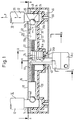
- einen Längsschnitt durch ein erfindungsgemäßes Bügelschloß in einer blockierten Stellung bei Ausübung einer großen Auszugskraft auf einen Schließdorn;
- Figur 2
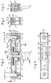
- einen Längsschnitt entsprechend Figur 1, ebenfalls in einer blockierten Stellung im unbelasteten Zustand;
- Figur 3
- einen Schnitt nach Linie A-B der Figur 2;
- Figur 4
- einen Schnitt nach Linie G-H der Figur 2 und
- Figur 5
- einen Schnitt nach Linie K-L der Figur 2.
- Figure 1
- a longitudinal section through a padlock according to the invention in a blocked position when exerting a large pulling force on a locking pin;
- Figure 2
- a longitudinal section corresponding to Figure 1, also in a blocked position in the unloaded state;
- Figure 3
- a section along line AB of Figure 2;
- Figure 4
- a section along line GH of Figure 2 and
- Figure 5
- a section along line KL of Figure 2.
In den Figuren 1-5 ist ein Schloßbügel mit 10 bezeichnet. Die beiden Bügelschenkel 12 des Schloßbügels sind mit je einem Schließdorn 14 ausgeführt. Die Schließdorne 14 sind in einem Schloßkörper aufgenommen, der ganz allgemein mit 16 bezeichnet ist. Der Schloßkörper 16 umfaßt ein rohrförmiges Schloßkörpergehäuse 18, das - wie aus Figuren 4 und 5 ersichtlich - Rechtecksquerschnitt besitzt. In das rohrförmige Schloßkörpergehäuse 18 ist von beiden Enden je ein Halteteil 20 eingeschoben. Die beiden Halteteile 20 und ihre im folgenden zu beschreibenden Eingerichteteile sind miteinander identisch, so daß die Beschreibung eines einzigen dieser Halteteile genügt. Das Halteteil 20 ist als ein Kunststoffspritzgußkörper ausgeführt, dessen Mittelabschnitt-wie in Figur 4 dargestellt - einen im wesentlichen pokalförmigen Querschnitt besitzt. In dem Mittelabschnitt ist eine nach oben offene Fühgrungsbahn 22 von teilkreisförmigem Querschnitt eingeformt. In dieser Führungsbahn 22 ist eine Verriegelungskugel 24 geführt. Die Führungskugel 24 ist zum Eingriff in eine Schließfläche 26 des Schließdorns 14 ausgebildet. An dem schließdornfernen Ende der Verriegelungskugel 24 liegt ein Stellelement 28 an. Dieses Stellelement 28 weist eine Führungsplatte 28a und einen Stellschenkel 28b auf. Der Stellschenkel 28b liegt mit seinem schließdornnahen Ende an der Verriegelungskugel 24 an. Die Führungsplatte 28a ist an dem Halteteil 20 im oberen Bereich des Pokalprofils oberhalb der Führungsbahn 22 in Pfeilrichtung 30 verschiebbar geführt. An dem schließdornfernen Ende des Stellschenkels 28b greift eine Schraubendruckfeder 32 an, die am Gehäuse 34a eines insgesamt mit 34 bezeichneten Schließzylinders abgestützt ist. Die Führungsbahn 22 erstreckt sich im Bereich der Verriegelungskugel 24 in ihrem Querschnitt über mehr als 180° der Verriegelungskugel 24, so daß auch dann noch, wenn unter normalen Betriebsumständen die Verriegelungskugel 24 in die Schließfläche 26 des Schließdorns 14 eingreift, die Verriegelungskugel 24 in Richtung des Doppelpfeils 38 kein wesentliches Spiel gegenüber der Führungsbahn 22 hat. Der Doppelpfeil 38 repräsentiert die Schließdorneinführungsrichtung bzw. Schließdornauszugsrichtung des Schließdorns 12 gegenüber dem Schloßkörper 16.In Figures 1-5, a lock bracket is designated 10. The two
Der Schließzylinder 34a ist mit einem Schließzylinderkern 34b ausgeführt und beruht auf dem Prinzip von schlüsselbrustgesteuerten federbelasteten Zuhaltungsstiftpaaren. Der Schlüssel 34c kann von unten durch einen Schlitz 40 des rohrförmigen Gehäuses 18 in den Schließzylinder eingeführt werden, so daß der Schließzylinderkern 34b gedreht werden kann. An dem oberen Ende des Schließzylinderkerns 34b ist eine Kurvenscheibe 44 angebracht, deren Form insbesondere in Figur 3 zu erkennen ist. An dieser Kurvenscheibe liegen gemäß Figur 3 die Führungsplatten 28a an und zwar im Bereich von radial vorspringenden Nocken 44a. Diese Nocken 44a sind so bemessen, daß in der Zuordnung gemäß Figur 2 die Verriegelungskugeln 24 durch die Stellelemente 28 in Eingriff mit den jeweiligen Schließflächen 26 gehalten werden.The
Da, wie schon ausgeführt, die Verriegelungskugeln 24 auch in dieser Stellung noch im wesentlichen spielfrei in der Richtung des Doppelpfeils 38 durch die jeweilige Führungsbahn 22 geführt sind, hat der Schließdorn 14 bei normaler Belastung in Auszugsrichtung gemäß 38 im wesentlichen kein Spiel gegenüber der Schließdornaufnahme 46 des jeweiligen Halteteils 20, in der er aufgenommen ist. Nur wenn, wie in Figur 1 dargestellt, eine sehr große Auszugskraft P auf den Schließdorn 14 ausgeübt wird, z.B. in der Größenordnung von 20 kN, so tritt eine elastische Verformung der Führungsbahn 22 auf, indem sich diese im Bereich der oberen Öffnung des Pokalprofils gemäß Figur 4 aufspreizt. Dann kann die Verriegelungskugel 24 in Richtung der Auszugskraft P nach oben durch die Schließfläche 26 mitgenommen werden. Nun ist, wie insbesondere aus Figuren 1,2 und 3 zu ersehen, am oberen Ende der Schließdornaufnahme 46 eine Widerlagerplatte 48 angeordnet, welche gemäß Figur 3 durch das rohrförmige Gehäuse 18 und das Halteteil 20 positioniert ist. Diese Widerlagerplatte 48 weist eine schlüssellochförmige Öffnung 50 auf mit einer Durchtrittsöffnung 50a für den Schließdorn 14 und einer Erweiterung 50b. Die Erweiterung 50b steht, wie aus Figuren 1 und 2 ersichtlich, in Längsrichtung des Schließdorns 14 der Kugel 24 gegenüber. Wenn die große Auszugskraft P ausgeübt wird, so versucht die Verriegelungskugel 24 durch die sich zwischen der Schließfläche 26 und der Verriegelungskugel 24 eintretende Nockenwirkung zunächst nach links auszuweichen und belastet damit das Stellelement 28. Da das Stellelemept 28 durch die Kurvenscheibe 44 starr abgestützt ist, wird aber die Verriegelungskugel 24 nicht in Richtung der Führungsbahn 22 seitlich verdrängt, sondern unter Deformation der Führungsbahn, d.h. des Pokalprofils gemäß Figur 4, eine kurze Strecke nach oben in Richtung der Kraft P mitgenommen. Dabei wird der Zustand gemäß Figur 1 erreicht, d.h. ein Zustand, bei dem die Kugel in die Erweiterung 50b der schlüssellochförmigen Öffnung 50 eintritt. Die Bemessung der Erweiterung 50b ist nun so getroffen, daß dann, wenn die Verriegelungskugel 24 einmal in den Bereich mit den unteren Kanten der Erweiterung 50b eingetreten ist, eine Selbsthemmung der Verriegelungskugel 24 zwischen der Schließfläche 26 und diesen Kanten der Erweiterung 50b eintritt. Dieser Zustand ist in Figur 1 dargestellt. Die Selbsthemmung der Verriegelungskugel 24 zwischen der Schließfläche 26 und der Erweiterung 50b läßt sich leicht durch entsprechende Bemessung der Tiefe der Schließfläche 26 und der Form und Größe der Erweiterung 50b einstellen. Selbsthemmung soll besagen, daß - wenn die Verriegelungskugel 24 einmal Eingriff mit der unteren Begrenzungskante der Erweiterung 50b gefunden hat und gleichzeitig noch an der Schließfläche 26 anliegt, die Kugel 24 nicht mehr das Bestreben hat, in Richtung des Doppelpfeils 30 nach links auszuweichen, sondern sich zwischen der Schließfläche 26 und der unteren Kante der Erweiterung 50b selbsthaltend einklemmt. Es wird also keine weitere Kraft auf das Stellelement 28 ausgeübt, welche den Schließzylinder 34 über seine Tragfähigkeit hin aus belasten könnte. Die bis zum Eingriff der Verriegelungskugel 24 in die Erweiterung 50b auftretende Stützkraft des Stellelements 28 auf die Verriegelungskugel 24 kann durch entsprechende Dimensionierung und Materialwahl so bemessen werden, daß eine Beschädigung des Schließzylinders 34 nicht eintreten kann und auch nicht der übrigen an der Abstützung beteiligten Komponenten. Wenn die Kraft P aufhört, so kehrt die Verriegelungskugel 24 aufgrund der elastischen Vorspannung, welche die Führungsbahn 22 bei der Aufwärtsbewegung der Verriegelungskugel 24 bis zum Eingriff mit der Erweiterung 50b erfahren hat, in die Stellung gemäß Figur 2 zurück.Since, as already stated, the locking
Die Auszugskraft P, die - wie gesagt - zur Verklemmung der Verriegelungskugel 24 zwischen der Schließfläche 26 und der Erweiterung 50b führt, ergibt eine Reaktionskraft in Pfeilrichtung 52 der Figur 1 auf die Widerlagerplatte 48. Diese Reaktionskraft wird aber im wesentlichen auf den Schließdorn 14 übertragen, der ja mit der Durchtrittsöffnung 50a der Widerlagerplatte 48 in Eingriff steht. Es wird also auch durch die Querkraft 52 keine wesentliche Belastung des Schloßeingerichtes erzeugt.The pull-out force P, which - as said - leads to the locking
Wenn das Schloß geöffnet werden soll, wird der Schließzylinderkern 34b mittels des Schlüssels 34c um 90° gedreht. Die Stellelemente 28 liegen dann an der Kurvenscheibe 44 im Bereich von Ausnehmungen 44b an und können gegen die Wirkung der Schraubendruckfedern 32 zurückweichen. Wenn nunmehr der Schloßbügel 10 aus dem Schloßkörper ausgezogen werden soll, so tritt wieder eine Nockenwirkung zwischen der Schließfläche 26 und der Verriegelungskugeln 24 ein. Die Verriegelungskugeln 24 weichen nunmehr aber nicht in Pfeilrichtung 38 nach oben aus, weil sie leichter in Pfeilrichtung 30 nach links ausweichen können. Die Kugeln 24 kommen also gar nicht erst in Eingriff mit der Erweiterung 50b und können deshalb unter Kompression der jeweiligen Schraubendruckfedern 32 soweit in Richtung des Pfeils 30 nach links ausweichen, bis die Verriegelungskugel 24 völlig aus der Schließfläche 26 ausgetaucht und der Schließdorn 14 vollständig ausgezogen werden kann. Notwendig ist dabei, daß die Verformungselastizität der Führungsbahn 22 und die Federkraft der Schraubendruckfeder 32 richtig aufeinander abgestimmt sind, um der Verriegelungskugel 24 ein Ausweichen in Pfeilrichtung 30 vor einem Ausweichen nach oben in Pfeilrichtung 38 zu ermöglichen.When the lock is to be opened, the
Die Form der Schließfläche 26, der Durchmesser der Verriegelungskugel 24 und die Vorspannung der Schraubendruckfeder 32 werden so aufeinander abgestimmt, daß bei einem normalen Öffnen des Schlosses nach vorheriger Entblockierung des Schließzylinders 34 der Schloßbügel 10 mit einer geringen Auszugskraft gelöst werden kann, wobei andererseits diese Auszugskraft nicht zu klein sein soll, damit nicht ein unbeabsichtigtes Herausfallen des Schloßbügels aus dem Schloßkörper eintreten kann.The shape of the locking
Das Wiedereinführen des Schließdorns 14 in die Schließdornaufnahme 46 ist auch nur dann möglich, wenn die Kurvenscheibe 44 in die vorbeschriebene Stellung verdreht ist, in welcher die Stellelemente 28 in Richtung auf den Schließzylinder 34 zurückweichen können. Dann kann der Schließdorn 14 beim Einschieben in die Schließdornaufnahme die Verriegelungskugel 24 zurückschieben, bis diese endlich in die Schließfläche 26 unter der Wirkung der Schraubendruckfeder 32 einfallen kann. Der Schlüssel 34c kann erst wieder in die Blockierstellung verdreht werden, nachdem die Schließfläche 26 in Flucht mit der Verriegelungskugel 24 getreten ist. Erst nach dieser Verdrehung kann entsprechend den Eigenschaften eines Schließzylinders mit federbelasteten Zuhaltungsstiftpaaren der Schlüssel abgezogen werden, so daß ein vorzeitiges Abziehen des Schlüssels bei nicht verriegeltem und gesichertem Schloß unmöglich ist. Der Benutzer hat deshalb, wenn er den Schlüssel nach dem Einstecken des Schließdorns 14 gezogen hat, die Gewissheit, daß er den Schließdorn weit genug eingeschoben und damit verriegelt und gesichert hat.The reinsertion of the locking
Zu beachten ist, daß die Widerlagerplatte 48 neben der Widerlagerfunktion auch eine Sicherungsfunktion erfüllen kann, indem sie die Zugänglichkeit des Schloßeingerichtes durch Aufbohren des Gehäuses und anschließendes Einführen von Eingriffselementen erschwert; außerdem versteift sie das Schloßgehäuse gegen Ausreißkräfte.It should be noted that the
Zu bemerken ist weiter, daß die Halteteile 20 formgleich ausgebildet sein können. Gleichwohl können die Formteile, wie aus Figur 4 ersichtlich, mit Paßstücken ausgeführt sein, die ein Zusammenstecken ermöglichen. Man erkennt in der Figur 4 einen Zapfen 60 und eine Zapfenaufnahme 62. Wenn die beiden formgleichen Halteteile innerhalb des Schloßgehäuses 18 zusammengesteckt werden, so findet der Zapfen des einen Halteteils 20 in die Zapfenaufnahme 62 des anderen Halteelements. Die Schließdornaufnahmen 46 sind Bestandteil des jeweiligen Halteteils 20. Die einander zugekehrten Enden der Halteteile 20 bilden auch eine Aufnahme 64 für den Schließzylinder, so daß dieser drehfest in dem Schloßkörper 16 gehalten ist. Die Festlegung der Halteteile 20 in Längsrichtung des rohrförmigen Schloßgehäuses 18 erfolgt durch Verstiftung bei 66. Man erkennt aus den Figuren 1-5, daß die Halteteile 20 dünnwandig ausgebildet sind, so daß sie im wesentlichen nur die innerhalb der Halteteile notwendigen Funktionsflächen festlegen. Die formschlüssige Aufnahme der Halteteile in dem rechteckförmigen Profil des rohrförmigen Gehäuses 18 erfolgt in den oberen Ecken 68 durch die Ränder des Pokalprofils und im Bodenbereich des Gehäuses durch den Stiel 70 des Pokalprofils. Somit kann die Elastizität der Führungsbahn 22 gegen Ausweichen der Verriegelungskugel 24 in Pfeilrichtung 38 durch die Abstützung der Ränder des Pokalprofils an den Seitenwänden des rohrförmigen Gehäuses eingestellt werden.It should also be noted that the holding
Die Anordnung des Schlüsseleingriffsschlitzes 40 an der unteren Gehäusewand erleichtert die Handhabung des Schlosses.The arrangement of the
Es muß natürlich dafür gesorgt sein, daß bei zurückgezogenem Schließdorn 14 die Verriegelungskugel 24 nicht in die Schließdornaufnahme 46 hineinfallen kann. Dies kann durch eine schließdornnahe Verengung der Führungsbahn 22 oder durch andere Anschlagmittel erfolgen.It must of course be ensured that the locking
Claims (28)
dadurch gekennzeichnet,
daß das Riegelelement (24) in der Schließdornauszugs richtung (38) von dem Stellelement (28) zumindest im Rahmen eines Bewegungsspiels mechanisch entkoppelt ist und daß das Riegelelement (24) durch eine auf den Schließdorn (14) wirkende Auszugskraft (P) selbsthemmend zwischen die Schließfläche (26) des Schließdorns (14) und ein Widerlager (50b) des Schloßkörpers (16) einklemmbar ist.Lock comprising a lock body (16) with at least one locking pin receptacle (46) and a locking pin (14) which can be inserted and locked in a closing pin insertion position in a closing pin closing position within the closing pin receptacle (46) and which can be locked in one of the closing pin insertion direction (38) opposite closing mandrel pull-out direction (38) can be pulled out of the closing mandrel receptacle (46), a locking element (24) along an essentially orthogonal to the closing mandrel insertion direction (38) for locking the closing mandrel (14) in its closing mandrel closing position within the lock body (16) Guideway (22) is adjustable between a release position and a locking position and engages in the locking position in a closing surface (26) of the locking pin (14), and in order to control the locking element (24) an R corresponding to a release position retracted position and a locking position corresponding to the locking position along the guideway (22) adjustable adjusting element (28) is provided,
characterized by
that the locking element (24) in the closing mandrel extension direction (38) is mechanically decoupled from the actuating element (28) at least within the scope of a play of motion and that the locking element (24) is self-locking between the locking force (P) acting on the closing mandrel (14) Closing surface (26) of the locking pin (14) and an abutment (50b) of the lock body (16) can be clamped.
dadurch gekennzeichnet,
daß das Widerlager (50b) an einem vorzugsweise plattenförmigen Widerlagerelement (48) ausgebildet ist, welches den Schließdorn (14) in seiner Schließdornschließstellung wenigstens teilweise umfaßt und sich an diesem gegen eine im wesentlichen quer zur Schließdornauszugsrichtung (38) gerichtete Querkraft abstützt, die sich bei Einwirkung einer Auszugskraft (P) auf den Schließdorn (14) als Folge der Einklemmung des Riegelelements (24) zwischen Schließfläche (26) und Widerlager (50b) ergibt.Lock according to claim 1,
characterized,
that the abutment (50b) on a preferably plate-shaped Abutment element (48) is formed, which at least partially encompasses the closing mandrel (14) in its closing mandrel closing position and is supported thereon against a transverse force which is essentially transverse to the closing mandrel extension direction (38) and which is exerted on the closing mandrel when a pulling force (P) is applied. 14) as a result of the clamping of the locking element (24) between the closing surface (26) and the abutment (50b).
dadurch gekennzeichnet,
daß das Widerlagerelement (48) innerhalb des Schloßkörpers (16) mit Bewegungsspiel quer zu der Schließdornauszugsrichtung (38) gelagert ist.Lock according to claim 2,
characterized,
that the abutment element (48) is mounted within the lock body (16) with movement play transversely to the closing mandrel extension direction (38).
dadurch gekennzeichnet,
daß das Widerlagerelement (48) an der Innenseite einer Gehäusewand (18) des Schloßkörpers (16) anliegt.Lock according to claim 2 or 3,
characterized,
that the abutment element (48) bears against the inside of a housing wall (18) of the lock body (16).
dadurch gekennzeichnet,
daß das Widerlagerelement (48) einen den Schließdorn (14) vollständig umschließenden Durchbruch (50) aufweist.Lock according to one of claims 2-4,
characterized,
that the abutment element (48) has an opening (50) completely enclosing the closing pin (14).
dadurch gekennzeichnet,
daß das Riegelelement (24) von einem Wälzkörper gebildet ist, welcher an einer der Schließdornaufnahme (46) zugekehrten Endfläche des Stellelements (28) frei anliegt.Lock according to one of claims 1-5,
characterized,
that the locking element (24) is formed by a roller body which bears freely against an end face of the adjusting element (28) facing the locking mandrel receptacle (46).
dadurch gekennzeichnet,
daß das Riegelelement (24) von einer Kugel gebildet ist.Lock according to claim 6,
characterized,
that the locking element (24) is formed by a ball.
dadurch gekennzeichnet,
daß das Widerlager (50b) von Kanten einer Erweiterung (50b) einer Schließdorndurchtrittsöffnung (50a) in einem Widerlagerelement (48) gebildet ist.Lock according to one of claims 1-7,
characterized,
that the abutment (50b) is formed by edges of an extension (50b) of a closing pin passage opening (50a) in an abutment element (48).
dadurch gekennzeichnet,
daß bei Rundquerschnitt des Schließdorns (14) und Kugelform des Riegelelements (24) die Schließdorndurchtrittsöffnung (50a) zusammen mit ihrer Erweiterung (50b) annähernd Schlüssellochform besitzt.Lock according to claim 8,
characterized,
that with a round cross-section of the locking pin (14) and spherical shape of the locking element (24), the locking pin passage opening (50a) together with its extension (50b) has approximately the shape of a keyhole.
dadurch gekennzeichnet,
daß das Riegelelement (24) durch das Stellelement (28) unter Federkraft (32) in die Verriegelungsstellung vorgespannt ist und daß der Schließdorn (14) unter nockenartigem Zusammenwirken mit dem Riegelelement (24) aus der Schließdornschließstellung zurückziehbar ist, wobei das Riegelelement (24) in Richtung auf die Freigabestellung ausweicht.Lock according to one of claims 1-9,
characterized,
that the locking element (24) is prestressed by the actuating element (28) under spring force (32) into the locking position and that the locking pin (14) can be retracted from the locking pin closing position by cam-like interaction with the locking element (24), the locking element (24) in the direction of the release position.
dadurch gekennzeichnet,
daß die Schließfläche (26) des Schließdorns (14) als eine Teilzylinder- oder Kugelkalottenfläche ausgebildet ist.Lock according to claim 10,
characterized,
that the closing surface (26) of the closing mandrel (14) is designed as a partial cylinder or spherical cap surface.
dadurch gekennzeichnet,
daß unter Normalgebrauchsbedingungen das Riegelelement (24) durch die Führungsbahn bis zum Eintritt in die Verriegelungsstellung im wesentlichen ohne ein in Schließdornauszugsrichtung (38) bestehendes Spiel geführt ist und daß eine Verklemmung des in seiner Verriegelungsstellung blockierten Riegelelements (24) zwischen der Schließfläche (26) und dem Widerlager (50b) erst bei Überschreiten eines vorbestimmten Werts einer an den Schließdorn (14) angelegten Auszugskraft (P) unter elastischer Auslenkung des Riegelelements (24) aus seiner Führungsbahn (22) eintritt.Lock according to one of claims 1-11,
characterized,
that, under normal conditions of use, the locking element (24) is guided through the guideway until entry into the locking position substantially without any play existing in the closing mandrel extension direction (38) and that the locking element (24) blocked in its locking position is jammed between the closing surface (26) and the abutment (50b) only enters when a predetermined value of a pull-out force (P) applied to the locking pin (14) with elastic deflection of the locking element (24) from its guideway (22).
dadurch gekennzeichnet,
daß die Führungsbahn (22) durch einen Führungskanal (22) innerhalb des Schloßkörpers (16) gebildet ist.Lock according to one of claims 1-12,
characterized,
that the guideway (22) is formed by a guide channel (22) within the lock body (16).
dadurch gekennzeichnet,
daß der Führungskanal (22) derart elastisch ausweitbar ist, daß er bei Überschreiten einer vorbestimmten Auszugskraft (P) an dem Schließdorn (14) ein elastisches Ausweichen des Riegelelements (24) aus seiner Führungsbahn (22) in Schließdornauszugsrichtung (38) gestattet.Lock according to claim 13,
characterized,
that the guide channel (22) can be expanded elastically in such a way that, when a predetermined pull-out force (P) on the locking pin (14) is exceeded, it allows the locking element (24) to move elastically out of its guideway (22) in the locking pin pull-out direction (38).
dadurch gekennzeichnet,
daß der Führungskanal (22) von einem Kunststoffteil (20) gebildet ist.Lock according to claim 14,
characterized,
that the guide channel (22) is formed by a plastic part (20).
dadurch gekennzeichnet,
daß das Stellelement (28) durch eine Blockiereinrichtung (34), insbesondere in Form eines Schließzylinders (34) in seiner Sperrstellung blockierbar ist.Lock according to one of claims 1-15,
characterized,
that the adjusting element (28) can be blocked in its locked position by a blocking device (34), in particular in the form of a locking cylinder (34).
dadurch gekennzeichnet,
daß die Blockiereinrichtung (34) eine drehbare Kurvenscheibe (44) besitzt, welche in einer Blockierstellung ein Ausweichen des Stellelements (28) aus der Sperrstellung in seine Rückzugsstellung blockiert und in einer Nichtblockierstellung ein Verschieben des Stellelements (28) aus seiner Sperrstellung in seine Rückzugsstellung gegen Federkraft (32) gestattet.Lock according to claim 16,
characterized,
that the blocking device (34) has a rotatable cam disc (44) which, in a blocking position, blocks the actuating element (28) from escaping from the blocking position into its retracted position and, in a non-blocking position, against moving the actuating element (28) from its blocking position into its retracting position Spring force (32) allowed.
dadurch gekennzeichnet,
daß die Sperreinrichtung (34) von einem Schließzylinder (34) mit einem Schließzylinderkern (34b) gebildet ist, wobei der Schließzylinderkern (34b) mit der Kurvenscheibe (44) zur gemeinsamen Verdrehung verbunden ist.Lock according to claim 17,
characterized,
that the locking device (34) is formed by a locking cylinder (34) with a locking cylinder core (34b), the locking cylinder core (34b) being connected to the cam disc (44) for common rotation.
dadurch gekennzeichnet,
daß der Schließzylinder (34) in einem Halteteil (20) aufgenommen ist, an welchem die Führungsbahn (22) für das Riegelelement (24) und/oder das Stellelement (28) ausgebildet ist.Lock according to one of claims 16-18,
characterized,
that the locking cylinder (34) is received in a holding part (20) on which the guide track (22) for the locking element (24) and / or the actuating element (28) is formed.
dadurch gekennzeichnet,
daß der Schloßkörper (16) ein rohrförmiges Gehäuse (18) und innerhalb dieses rohrförmigen Gehäuses (18) einen Halteteil (20) umfaßt, in welchem die Führungsbahn (22) für das Riegelelement (24) und/oder das Stellelement (28) ausgebildet ist.Lock according to one of claims 1-19,
characterized,
that the lock body (16) comprises a tubular housing (18) and within this tubular housing (18) a holding part (20) in which the guide track (22) for the locking element (24) and / or the actuating element (28) is formed .
dadurch gekennzeichnet,
daß in dem Halteteil (20) eine Aufnahmekammer (46) für den Schließdorn (14) ausgebildet ist und daß die Führungsbahn (22) des Riegelelements (24) in diese Aufnahmekammer (46) mündet.Lock according to claim 20,
characterized,
that in the holding part (20) has a receiving chamber (46) for the locking pin (14) is formed and that the guideway (22) of the locking element (24) opens into this receiving chamber (46).
dadurch gekennzeichnet,
daß das Riegelelement (24) in seiner Verriegelungsstellung gegen Übertritt aus seiner Führungsbahn (22) in die Schließdornaufnahme (46) auch dann gesichert ist, wenn der Schließdorn (14) aus der Schließdornaufnahme (46) zurückgezogen ist.Lock according to one of claims 1-21,
characterized,
that the locking element (24) is secured in its locking position against passage from its guideway (22) into the locking pin receptacle (46) even when the locking pin (14) is withdrawn from the locking pin receptacle (46).
dadurch gekennzeichnet,
daß an einem der Schließdornaufnahme (46) nahen Ende der Führungsbahn (22) eine Führungsbahnverengung vorgesehen ist.Lock according to claim 22,
characterized,
that a guideway narrowing is provided at an end of the guideway (22) near the closing mandrel receptacle (46).
dadurch gekennzeichnet,
daß es als ein Bügelschloß mit einem Schloßbügel (10) ausgebildet ist, wobei dieser Schloßbügel (10) an jedem Ende eines seiner beiden Bügelschenkel (12) je einen Schließdorn (14) zur Aufnahme in je eine zugehörige Schließdornaufnahme (46) des Schloßkörpers (16) aufweist.Lock according to one of claims 1-23,
characterized,
that it is designed as a shackle lock with a lock shackle (10), this lock shackle (10) at each end of one of its two shackle legs (12) each having a locking pin (14) for receiving in an associated locking pin holder (46) of the lock body (16 ) having.
dadurch gekennzeichnet,
daß der Schloßkörper (16) im wesentlichen symmetrisch ausgebildet ist in bezug auf eine Symmetrieebene des Schloßbügels (10), wobei eine Blockiereinrichtung (34) in einem mittleren Bereich zwischen den beiden Schließdornaufnahmen (46) angeordnet und den beiden Schließdornaufnahmen (46) gemeinsam ist.Lock according to claim 24,
characterized,
that the lock body (16) is essentially symmetrical with respect to a plane of symmetry of the lock shackle (10), a blocking device (34) being arranged in a central region between the two locking pin receptacles (46) and the two locking pin receptacles (46) being common.
dadurch gekennzeichnet,
daß die Blockiereinrichtung (34) in einer Blockiereinrichtungshaltekammer (64) innerhalb des Schloßkörpers (16) untergebracht ist, welche durch zwei in der Symmetrieebene zusammenstoßende Halteteile (20) begrenzt ist und wobei von diesen beiden Halteteilen (20) jeder eine Führungsbahn (22) für ein jeweils zugehöriges Riegelelement (24) und/oder Stellelement (28) bildet.Lock according to claim 25,
characterized,
that the blocking device (34) is accommodated in a blocking device holding chamber (64) within the lock body (16), which is delimited by two holding parts (20) colliding in the plane of symmetry, and each of these two holding parts (20) has a guideway (22) for forms an associated locking element (24) and / or adjusting element (28).
dadurch gekennzeichnet,
daß die Blockiereinrichtung (34) durch Schlüssel (34c) betätigbar ist und daß zur Einführung eines Schlüssels (34c) in einer von dem Scheitelpunkt des Schloßbügels abgelegenen Seitenfläche des Schloßkörpers (16) eine Schlüsseleinführungsöffnung (40) vorgesehen ist.Lock according to claim 25 or 26,
characterized,
that the blocking device (34) can be actuated by key (34c) and that a key insertion opening (40) is provided for inserting a key (34c) in a side surface of the lock body (16) remote from the apex of the lock shackle.
dadurch gekennzeichnet,
daß der Schloßkörper (16) ein rohrförmiges Gehäuse (18) umfaßt, welches den Abstand zwischen den beiden Schließdornaufnahmen (46) des Schloßkörpers (16) überbrückt.Lock according to one of claims 24-27,
characterized,
that the lock body (16) comprises a tubular housing (18) which bridges the distance between the two locking pin receptacles (46) of the lock body (16).
Applications Claiming Priority (2)
| Application Number | Priority Date | Filing Date | Title |
|---|---|---|---|
| DE4329511A DE4329511A1 (en) | 1993-09-01 | 1993-09-01 | Long shackle lock with self-locking clamping of a bolt element |
| DE4329511 | 1993-09-01 |
Publications (3)
| Publication Number | Publication Date |
|---|---|
| EP0641909A2 true EP0641909A2 (en) | 1995-03-08 |
| EP0641909A3 EP0641909A3 (en) | 1995-09-27 |
| EP0641909B1 EP0641909B1 (en) | 1998-11-11 |
Family
ID=6496581
Family Applications (1)
| Application Number | Title | Priority Date | Filing Date |
|---|---|---|---|
| EP94113245A Expired - Lifetime EP0641909B1 (en) | 1993-09-01 | 1994-08-24 | Padlock, with self-blocking dead locking of a bolt element |
Country Status (4)
| Country | Link |
|---|---|
| EP (1) | EP0641909B1 (en) |
| DE (2) | DE4329511A1 (en) |
| ES (1) | ES2124824T3 (en) |
| TW (1) | TW251331B (en) |
Cited By (3)
| Publication number | Priority date | Publication date | Assignee | Title |
|---|---|---|---|---|
| DE19638188A1 (en) * | 1996-09-18 | 1998-03-19 | Bremicker Soehne Kg A | U-lock |
| EP1160405A1 (en) * | 2000-05-30 | 2001-12-05 | ABUS August Bremicker Söhne KG | Padlock |
| US8839650B2 (en) | 2008-06-25 | 2014-09-23 | Robert David Zuraski | Portable lock with modular cable |
Families Citing this family (2)
| Publication number | Priority date | Publication date | Assignee | Title |
|---|---|---|---|---|
| FR2982302B1 (en) * | 2011-11-09 | 2014-11-07 | Thirard Ets | ELECTROMECHANICAL LATCH |
| DE102015117253A1 (en) * | 2015-10-09 | 2017-04-13 | ABUS August Bremicker Söhne KG | padlock |
Citations (6)
| Publication number | Priority date | Publication date | Assignee | Title |
|---|---|---|---|---|
| DE373261C (en) * | 1921-05-26 | 1923-04-10 | Robert Fromm | Padlock |
| US1511057A (en) * | 1923-03-05 | 1924-10-07 | Yale & Towne Mfg Co | Padlock |
| US1607758A (en) * | 1926-11-23 | John junkunc | ||
| US2460474A (en) * | 1947-07-18 | 1949-02-01 | Master Lock Co | Plug retaining plate for lock cylinders |
| US3194033A (en) * | 1963-09-03 | 1965-07-13 | Slaymaker Lock Company | Padlock and the like |
| US5189893A (en) * | 1990-09-17 | 1993-03-02 | Aug. Winkhaus Gmbh & Co. Kg | Shackle lock with a pivotable locking arrangement |
-
1993
- 1993-09-01 DE DE4329511A patent/DE4329511A1/en not_active Withdrawn
- 1993-09-07 TW TW082107294A patent/TW251331B/zh active
-
1994
- 1994-08-24 DE DE59407268T patent/DE59407268D1/en not_active Expired - Lifetime
- 1994-08-24 EP EP94113245A patent/EP0641909B1/en not_active Expired - Lifetime
- 1994-08-24 ES ES94113245T patent/ES2124824T3/en not_active Expired - Lifetime
Patent Citations (6)
| Publication number | Priority date | Publication date | Assignee | Title |
|---|---|---|---|---|
| US1607758A (en) * | 1926-11-23 | John junkunc | ||
| DE373261C (en) * | 1921-05-26 | 1923-04-10 | Robert Fromm | Padlock |
| US1511057A (en) * | 1923-03-05 | 1924-10-07 | Yale & Towne Mfg Co | Padlock |
| US2460474A (en) * | 1947-07-18 | 1949-02-01 | Master Lock Co | Plug retaining plate for lock cylinders |
| US3194033A (en) * | 1963-09-03 | 1965-07-13 | Slaymaker Lock Company | Padlock and the like |
| US5189893A (en) * | 1990-09-17 | 1993-03-02 | Aug. Winkhaus Gmbh & Co. Kg | Shackle lock with a pivotable locking arrangement |
Cited By (5)
| Publication number | Priority date | Publication date | Assignee | Title |
|---|---|---|---|---|
| DE19638188A1 (en) * | 1996-09-18 | 1998-03-19 | Bremicker Soehne Kg A | U-lock |
| EP1160405A1 (en) * | 2000-05-30 | 2001-12-05 | ABUS August Bremicker Söhne KG | Padlock |
| US6584815B2 (en) | 2000-05-30 | 2003-07-01 | ABUS August Bremicker Söhne KG | Hoop lock |
| US8839650B2 (en) | 2008-06-25 | 2014-09-23 | Robert David Zuraski | Portable lock with modular cable |
| EP2628667B1 (en) * | 2008-06-25 | 2018-09-12 | Ingersoll-Rand Company | Portable lock with modular cable |
Also Published As
| Publication number | Publication date |
|---|---|
| ES2124824T3 (en) | 1999-02-16 |
| EP0641909B1 (en) | 1998-11-11 |
| DE4329511A1 (en) | 1995-03-02 |
| DE59407268D1 (en) | 1998-12-17 |
| TW251331B (en) | 1995-07-11 |
| EP0641909A3 (en) | 1995-09-27 |
Similar Documents
| Publication | Publication Date | Title |
|---|---|---|
| EP0326096B1 (en) | Releasable connecting device for two elements | |
| EP1068985A1 (en) | Locking device and anchoring system | |
| DE2742166B1 (en) | Device for locking and unlocking mold plates of an injection molding or compression mold | |
| DE4408024C5 (en) | safety switch | |
| DE2441463C3 (en) | Cylinder lock with an axially displaceable cylinder core, especially for a steering lock in motor vehicles | |
| DE2058802A1 (en) | Lock-operated anti-theft device, preferably for motor vehicles | |
| EP2643536B1 (en) | Mechanical or mechatronical actuatable locking system | |
| EP1114232B1 (en) | Device for guiding and limiting the travel of a sliding door element | |
| DE10011626C1 (en) | Emergency stop button system | |
| EP0641909B1 (en) | Padlock, with self-blocking dead locking of a bolt element | |
| EP1325995B1 (en) | Interlock device preventing the simultaneous opening of elements, in particular for a drawer cabinet | |
| DE19914860A1 (en) | Guiding and limiting movement device for sliding door component has receiving and stop component working in conjunction with centering component, with receiving and stop component | |
| DE102005026930B4 (en) | padlock | |
| DE10011625C1 (en) | Emergency off button has locking arrangement can be inserted in one of two guide paths, one allowing unlocking only by pulling and the other only by turning | |
| EP1785558B1 (en) | Lock, in particular for safe | |
| DE868122C (en) | Latch lock with locking device | |
| DE1932154A1 (en) | Magnetic holding device | |
| AT389915B (en) | LOCK WITH SELF-TENSIONING NUT | |
| AT230762B (en) | Safety lock | |
| DE102011000443A1 (en) | Lock cylinder has latching units that are comprised such that cylinder core is pressed against stopper only after complete insertion of key which brings tumbler elements to release position | |
| DE3833757A1 (en) | Lock for a door or the like | |
| DE4236764C1 (en) | Central locking device for drawer cabinets | |
| DE10322160A1 (en) | Electromagnetic lock has locking pin inserted in slot defined between outer and inner blocking devices | |
| DE10053672A1 (en) | Lock cylinder with tumbler channel shapes channel wall loaded by sprung tumbler as conical expansion or step and so set back from center axial plane to prevent tumbler engageably lifting. | |
| EP1030016A2 (en) | Espagnolette lock with safety closing mechanism |
Legal Events
| Date | Code | Title | Description |
|---|---|---|---|
| PUAI | Public reference made under article 153(3) epc to a published international application that has entered the european phase |
Free format text: ORIGINAL CODE: 0009012 |
|
| AK | Designated contracting states |
Kind code of ref document: A2 Designated state(s): DE DK ES FR GB NL |
|
| PUAL | Search report despatched |
Free format text: ORIGINAL CODE: 0009013 |
|
| AK | Designated contracting states |
Kind code of ref document: A3 Designated state(s): DE DK ES FR GB NL |
|
| 17P | Request for examination filed |
Effective date: 19960325 |
|
| 17Q | First examination report despatched |
Effective date: 19970610 |
|
| GRAG | Despatch of communication of intention to grant |
Free format text: ORIGINAL CODE: EPIDOS AGRA |
|
| GRAG | Despatch of communication of intention to grant |
Free format text: ORIGINAL CODE: EPIDOS AGRA |
|
| GRAH | Despatch of communication of intention to grant a patent |
Free format text: ORIGINAL CODE: EPIDOS IGRA |
|
| GRAH | Despatch of communication of intention to grant a patent |
Free format text: ORIGINAL CODE: EPIDOS IGRA |
|
| GRAA | (expected) grant |
Free format text: ORIGINAL CODE: 0009210 |
|
| AK | Designated contracting states |
Kind code of ref document: B1 Designated state(s): DE DK ES FR GB NL |
|
| PG25 | Lapsed in a contracting state [announced via postgrant information from national office to epo] |
Ref country code: GB Free format text: LAPSE BECAUSE OF NON-PAYMENT OF DUE FEES Effective date: 19981111 Ref country code: FR Free format text: LAPSE BECAUSE OF FAILURE TO SUBMIT A TRANSLATION OF THE DESCRIPTION OR TO PAY THE FEE WITHIN THE PRESCRIBED TIME-LIMIT Effective date: 19981111 |
|
| REF | Corresponds to: |
Ref document number: 59407268 Country of ref document: DE Date of ref document: 19981217 |
|
| PG25 | Lapsed in a contracting state [announced via postgrant information from national office to epo] |
Ref country code: DK Free format text: LAPSE BECAUSE OF FAILURE TO SUBMIT A TRANSLATION OF THE DESCRIPTION OR TO PAY THE FEE WITHIN THE PRESCRIBED TIME-LIMIT Effective date: 19990211 |
|
| REG | Reference to a national code |
Ref country code: ES Ref legal event code: FG2A Ref document number: 2124824 Country of ref document: ES Kind code of ref document: T3 |
|
| EN | Fr: translation not filed | ||
| GBV | Gb: ep patent (uk) treated as always having been void in accordance with gb section 77(7)/1977 [no translation filed] |
Effective date: 19981111 |
|
| PLBE | No opposition filed within time limit |
Free format text: ORIGINAL CODE: 0009261 |
|
| STAA | Information on the status of an ep patent application or granted ep patent |
Free format text: STATUS: NO OPPOSITION FILED WITHIN TIME LIMIT |
|
| 26N | No opposition filed | ||
| PGFP | Annual fee paid to national office [announced via postgrant information from national office to epo] |
Ref country code: ES Payment date: 20010809 Year of fee payment: 8 |
|
| NLS | Nl: assignments of ep-patents |
Owner name: TRELOCK GMBH |
|
| PG25 | Lapsed in a contracting state [announced via postgrant information from national office to epo] |
Ref country code: ES Free format text: LAPSE BECAUSE OF NON-PAYMENT OF DUE FEES Effective date: 20020825 |
|
| REG | Reference to a national code |
Ref country code: ES Ref legal event code: FD2A Effective date: 20030912 |
|
| PGFP | Annual fee paid to national office [announced via postgrant information from national office to epo] |
Ref country code: NL Payment date: 20090831 Year of fee payment: 16 |
|
| PGFP | Annual fee paid to national office [announced via postgrant information from national office to epo] |
Ref country code: DE Payment date: 20100709 Year of fee payment: 17 |
|
| REG | Reference to a national code |
Ref country code: NL Ref legal event code: V1 Effective date: 20110301 |
|
| PG25 | Lapsed in a contracting state [announced via postgrant information from national office to epo] |
Ref country code: NL Free format text: LAPSE BECAUSE OF NON-PAYMENT OF DUE FEES Effective date: 20110301 |
|
| REG | Reference to a national code |
Ref country code: DE Ref legal event code: R082 Ref document number: 59407268 Country of ref document: DE Representative=s name: SWEN HENTRICH, DE |
|
| REG | Reference to a national code |
Ref country code: DE Ref legal event code: R082 Ref document number: 59407268 Country of ref document: DE Representative=s name: HENTRICH, SWEN, DIPL.-PHYS. DR.RER.NAT., DE Effective date: 20120127 Ref country code: DE Ref legal event code: R081 Ref document number: 59407268 Country of ref document: DE Owner name: TRELOCK GMBH, DE Free format text: FORMER OWNER: TRELOCK GMBH, 48301 NOTTULN, DE Effective date: 20120127 |
|
| REG | Reference to a national code |
Ref country code: DE Ref legal event code: R119 Ref document number: 59407268 Country of ref document: DE Effective date: 20120301 |
|
| PG25 | Lapsed in a contracting state [announced via postgrant information from national office to epo] |
Ref country code: DE Free format text: LAPSE BECAUSE OF NON-PAYMENT OF DUE FEES Effective date: 20120301 |