EP1325995B1 - Interlock device preventing the simultaneous opening of elements, in particular for a drawer cabinet - Google Patents
Interlock device preventing the simultaneous opening of elements, in particular for a drawer cabinet Download PDFInfo
- Publication number
- EP1325995B1 EP1325995B1 EP02406051A EP02406051A EP1325995B1 EP 1325995 B1 EP1325995 B1 EP 1325995B1 EP 02406051 A EP02406051 A EP 02406051A EP 02406051 A EP02406051 A EP 02406051A EP 1325995 B1 EP1325995 B1 EP 1325995B1
- Authority
- EP
- European Patent Office
- Prior art keywords
- drawer
- drawers
- row
- cabinet
- movable elements
- Prior art date
- Legal status (The legal status is an assumption and is not a legal conclusion. Google has not performed a legal analysis and makes no representation as to the accuracy of the status listed.)
- Expired - Lifetime
Links
- 210000000038 chest Anatomy 0.000 abstract 2
- 210000002105 tongue Anatomy 0.000 description 10
- 230000001052 transient effect Effects 0.000 description 7
- 239000000284 extract Substances 0.000 description 2
- 238000000034 method Methods 0.000 description 2
- 230000001681 protective effect Effects 0.000 description 2
- 241001136792 Alle Species 0.000 description 1
- 238000013475 authorization Methods 0.000 description 1
- 230000001419 dependent effect Effects 0.000 description 1
- 230000003028 elevating effect Effects 0.000 description 1
- 230000005484 gravity Effects 0.000 description 1
- 230000006266 hibernation Effects 0.000 description 1
- 238000004519 manufacturing process Methods 0.000 description 1
- 239000000463 material Substances 0.000 description 1
- 210000000056 organ Anatomy 0.000 description 1
- 238000003825 pressing Methods 0.000 description 1
- 230000000284 resting effect Effects 0.000 description 1
- 230000001960 triggered effect Effects 0.000 description 1
Images


Classifications
-
- E—FIXED CONSTRUCTIONS
- E05—LOCKS; KEYS; WINDOW OR DOOR FITTINGS; SAFES
- E05B—LOCKS; ACCESSORIES THEREFOR; HANDCUFFS
- E05B65/00—Locks or fastenings for special use
- E05B65/46—Locks or fastenings for special use for drawers
- E05B65/462—Locks or fastenings for special use for drawers for two or more drawers
- E05B65/463—Drawer interlock or anti-tilt mechanisms, i.e. when one drawer is open, at least one of the remaining drawers is locked
- E05B65/464—Drawer interlock or anti-tilt mechanisms, i.e. when one drawer is open, at least one of the remaining drawers is locked comprising two or more lock elements aligned in end-to-end abutting relation
Definitions
- the present invention relates to a pull-out protection for a drawer cabinet. Furthermore, the invention relates to a provided with the pull-out drawer cabinet.
- Cabinets and cabinet systems are used in many areas of trade and industry, for example as stationary or mobile tool cabinets in the field of industrial manufacturing or in the workshop area. Since in such cabinets often heavy tools or workpieces are stored, a tilting of the cabinets when opening drawers must be avoided. It has therefore long been known to provide such cabinets with a single pull-out protection. This is to ensure that not several drawers at the same time, but only a drawer, can be opened, so as to reduce the resulting from the pulled out drawers tilting moment.
- a locking device which comprises at least one cabinet having a plurality of retractable drawers separated from each other, which are arranged on a housing of the cabinet, wherein compartments of the cabinet by a closure device can be locked and unlocked to which each of these compartments is provided with a switchable lock associated with it.
- a closure device In the closing device, an access authorization device is also provided.
- Each compartment can be locked and unlocked separately with its lock.
- the locking device known from WO-A-96/25577 already has the advantage over the prior art devices that the locking device can be formed in the rear area of the cabinet, whereas in the earlier cabinets it is usually a lateral attachment of the locking device was provided.
- the arrangement of the safety edge according to WO-A-96/25577 is associated with the disadvantage that it can be triggered abusive even with retracted drawers by very flat objects when such an object is inserted between two drawers and up to the Safety edge can get.
- This abusive process is facilitated in particular by the fact that the object (eg a ruler) between the drawers is quasi guided and thus not even special finger skills are necessary to allow the abuse.
- the closing strip according to DE-A-43 42 101 consists of a plurality of rotary elements which are mounted on a common pin, the rotary elements also have an organ which is designed so that it is an element in the rotation of an adjacent element around a predetermined angle over a certain axial stroke is removed, wherein the pin is vertically installed in the piece of furniture, that at an angular position of the elements, which does not require a distance, a radial projection or a groove of each of these elements in the trajectory of a projection of a drawer is arranged at their Opening the associated element rotates by the predetermined angle, whereby it causes the axial removal of an adjacent element and returns the rotated element when closing the drawer back to its original position, the pin at its lower part a fixed stop with a lifting member for lifting the abutting element in its rotation by the predetermined angle, while the upper end of
- the rotary elements are all identical and designed to abut each other, wherein the removal member has an axial lug of an element which is at rest in a recess of an adjacent element and after rotation of the element to a certain angle emerges from this recess.
- the main disadvantage of the device according to DE-A-43 42 101 lies in the attempt to provide a multi-stable device in which the state in which one of the drawers is mounted, a very specific turning device is locked and thus locks the entire system, while in the device according to WO-A-96/25577 a bistable setting is provided in which the locking system when opening a drawer enters a lock state that is the same for all drawers.
- This safety catch has a plurality of substantially arranged in a row and displaceable elements, a guide means for guiding the substantially arranged in a row and displaceable elements, as well as associated with the drawer to be secured adjusting elements for adjusting the vertical position of substantially in a series of arranged and movable elements. Furthermore, a limiting means for limiting the displaceability of substantially arranged in a row and displaceable elements is present.
- the adjusting elements cooperate with the drawer to be secured so that they move at the beginning of a pull-out movement of one of the drawer to be secured one of the substantially arranged in a row and displaceable elements and all other in one of the directions of the series elements, but be moved back to its original position by gravity after a certain extension position of the drawn drawer.
- the invention solves the problem by a device according to claim 1.
- the measures of the invention initially have the consequence that the device can be operated together with the locking device according to WO-A-96/25577, so that the measures of the invention an additional Provide protection if needed.
- This rather modular concept should be regarded as a particular advantage of the invention.
- the measures of the invention provide additional protection against abuse and transient protection in the event that several drawers can be mounted at the same time. After mounting a drawer, the protection of the inventive device refers only to the abuse protection.
- the necessary protective measures are to be effected by simple means, compared with the complicated measures proposed in DE-A-43 42 101.
- the drawer cabinet 10 has a plurality of drawers 12. These drawers are secured with a single pull-out device 48, which is operated via a lock 46 and a safety bar 44. The drawers are guided by guides 14 when moving.
- the individual pull-out protection is formed by the closure profile, as disclosed in WO-A-96/25577 and also in EP-A-1 035 285.
- the technical details of the function of the closing strip are shown in FIGS. 2a and 2b, reference being made to the prior art in this respect.
- the closing mechanism is actuated by a closing tongue 52, which is formed on corresponding, attached to the end of the drawer slide 50.
- these locking tongues have an elevation element, each with a ramp 54 and 56 fore and aft, and a flat part 58 formed between the ramps.
- the ramp is inclined by about 10 ° to 40 °, preferably by 20 °, said angle can also assume a value outside the specified range.
- a respective guide rail 40 is attached, in each of which a guide groove 42 is formed.
- this guide 42 now flat flat plate 20 are now embedded.
- These plates 20 are formed so that they can slide vertically in the guide groove.
- they have a rectangular cutout 24 into which the closing tongues 52 with their additional elevating elements can be moved out of the two ramps 54 and 56 and the flat part 58, but by pressing the two adjacent platelets apart.
- a small, rectangular cutout is also formed on the underside of the platelets, which functionally cooperates with the upper cutout 24 on the plate 20 arranged underneath as described above.
- the lowermost plate 20 rests on a connecting element 28, with which the two guide rails 40 are connected.
- a connecting element 28 with which the two guide rails 40 are connected.
- a connecting element 26 which is additionally formed as an upper delimiting element of the movement of the platelets 20.
- the distance of the uppermost plate 20 in the state in which all the plates 20 lie on each other and is not moved by any closing tongue 52, from the upper connecting and limiting element 26 is just selected so that only one elevation element with respect to its flat portion 58 transiently through the successive platelets 20 fits through. If the flat part 58 of an elevation element is located in an opening 24 between two platelets 20, then the uppermost platelet lies just on the upper connecting and delimiting element 26. A further lifting of the platelets 20 is not possible in this state, so that another drawer 12 can not be pulled out. This function is shown in particular in FIG.
- the front ramp 54 is arranged on the closing tongue 52 so that, when the drawer 12 is completely retracted, it is just resting against the associated upper plate.
- the transient pull-out protection according to the present invention still acts in a wider sense.
- the platelets 20 are arranged so that each one platelet 20 protects the space between two drawers 12. This prevents that can be manipulated on the closing mechanism 26, 27 with an object which is passed between two retracted drawers 12 therethrough. In the present embodiment, therefore, the opening 24 of a small plate is always covered by the drawer both in the lower, stationary state and in the raised state.
- this fact is ensured by the fact that the total height of a single plate 20 is dimensioned at 25 mm, while the opening 24 together with the - small in the embodiment of the lower section of the plate 20 is not more than 5 - 8 mm, corresponding to the height of the flat part 58 on the closing tongue 52, so that the concealing part of the plate 20 is always protective in both the raised and in the lowered state in front of the accessible through the gap between two drawers part of the closing bar.
- the additional, transient pull-out protection is modularly constructed such that it when inserting various drawers 12 in the drawer cabinet 10 does not need to be changed or adjusted.
- the height of a small plate in the exemplary embodiment is 25 mm. This allows the modular use of drawers with a height of for example 25 mm, 50 mm, 75 mm 100 mm or another multiple of 25 mm, without having to adjust the pull-out protection in any way. Since the closing mechanism according to the prior art according to WO-A-96/25577 and also according to EP-A-1 035 285 allows different drawer heights, an optimal adjustment of different types of drawer is possible.
Abstract
Description
Die vorliegende Erfindung betrifft eine Auszugsicherung, für einen Schubladenschrank. Des weiteren betrifft die Erfindung einen mit der Auszugsicherung versehenen Schubladenschrank.The present invention relates to a pull-out protection for a drawer cabinet. Furthermore, the invention relates to a provided with the pull-out drawer cabinet.
Schränke und Schranksysteme werden in vielen Bereichen des Handels und der Industrie eingesetzt, so zum Beispiel als stationäre oder mobile Werkzeugschränke im Bereich der industriellen Fertigung oder im Werkstattbereich. Da in solchen Schränken oftmals schwere Werkzeuge oder Werkstücke aufbewahrt werden, muss ein Verkippen der Schränke beim Öffnen von Schubladen vermieden werden. Es ist deshalb bereits seit langem bekannt, derartige Schränke mit einer Einzelauszugsicherung zu versehen. Diese soll sicherstellen, dass nicht mehrere Schubladen gleichzeitig, sondern lediglich eine Schublade, geöffnet werden kann, um so das aus den herausgezogenen Schubladen resultierende Kippmoment zu reduzieren.Cabinets and cabinet systems are used in many areas of trade and industry, for example as stationary or mobile tool cabinets in the field of industrial manufacturing or in the workshop area. Since in such cabinets often heavy tools or workpieces are stored, a tilting of the cabinets when opening drawers must be avoided. It has therefore long been known to provide such cabinets with a single pull-out protection. This is to ensure that not several drawers at the same time, but only a drawer, can be opened, so as to reduce the resulting from the pulled out drawers tilting moment.
Es hat sich gezeigt, dass in einigen Anwendungsbereichen Sicherheitsanforderungen zu erfüllen sind, die frühere Schränke nicht erfüllen. So soll zum Beispiel verhindert werden, dass beliebige Personen Zugriff auf sicherheitssensitive Teile oder Werkzeuge haben, die in Schränken gelagert sind. Dies wäre an sich einfach dadurch zu lösen, dass diese Elemente in Abteile der Schränke verschlossen werden. Um hierauf zuzugreifen, müssten die entsprechenden Abteile jedoch ständig auf- und zugeschlossen werden, was den Arbeitsablauf erheblich stören würde. Zudem müsste jedes Abteil mit einem eigenen Schloss und Schlüssel versehen werden, was den konstruktiven Aufwand erhöht. Ausserdem wäre mit einer solchen Lösung auch ein relativ grosser organisatorischer Aufwand verbunden, da kontrolliert werden müsste, welche Personen für welche Schubladen Schlüssel erhalten. Bei Änderung der Zugriffsberechtigungen müsste der Rücklauf von einer Vielzahl von Schlüsseln überwacht und deren Neuausgabe organisiert werden.It has been found that in some applications security requirements must be met that do not meet earlier cabinets. For example, it should be prevented that any persons have access to safety-sensitive parts or tools stored in cabinets are. This would in itself be solved simply by closing these elements in compartments of the cabinets. To access this, however, the corresponding compartments would have to be constantly opened and closed, which would significantly disrupt the workflow. In addition, each compartment would have to be provided with its own lock and key, which increases the design effort. In addition, a relatively large organizational effort would be associated with such a solution, as would have to be controlled, which persons receive keys for which drawers. If the access rights were changed, the return would have to be monitored by a large number of keys and their reissuing organized.
Aus der WO-A-96/25577 ist eine Schliesseinrichtung bekannt, das zumindest einen Schrank umfasst, der mehrere, voneinander abgetrennte ausziehbare Schubladen aufweist, die an einem Gehäuse des Schrankes angeordnet sind, wobei Abteile des Schranks durch eine Verschlusseinrichtung ver- und entriegelbar sind, wozu jedes dieser Abteile mit einer ihm zugeordneten schaltbaren Sperre versehen ist. Bei der Schliesseinrichtung ist ferner eine Zugangsberechtigungseinrichtung vorgesehen. Jedes Abteil ist mit seiner Sperre separat ver- und entriegelbar. Die aus der WO-A-96/25577 bekannte Schliesseinrichtung hat - gegenüber den Einrichtungen des früheren Standes der Technik - schon den Vorteil, dass die Schliesseinrichtung im hinteren Bereich des Schrankes ausgebildet werden kann, während bei den früheren Schränken zumeist eine seitliche Anbringung der Schliesseinrichtung vorgesehen war.From WO-A-96/25577 a locking device is known which comprises at least one cabinet having a plurality of retractable drawers separated from each other, which are arranged on a housing of the cabinet, wherein compartments of the cabinet by a closure device can be locked and unlocked to which each of these compartments is provided with a switchable lock associated with it. In the closing device, an access authorization device is also provided. Each compartment can be locked and unlocked separately with its lock. The locking device known from WO-A-96/25577 already has the advantage over the prior art devices that the locking device can be formed in the rear area of the cabinet, whereas in the earlier cabinets it is usually a lateral attachment of the locking device was provided.
Es hat sich aber herausgestellt, dass die Schliesseinrichtung der WO-A-96/25577 noch bezüglich einiger Punkte verbessert werden kann. Einerseits ist das Problem aufgetreten, dass die an und für sich ausgezeichnet wirkende Einzelauszugsicherung einen transienten Bereich lässt, in der sie nicht vollumfänglich wirken kann, nämlich beim gleichzeitigen Ausziehen von zwei - oder sogar mehr - Schubladen. Dies kommt insbesondere dann vor, wenn der Schubladenschrank auf Rollen bewegt wird, sei es, dass er selbst mit Rollen versehen ist oder aber, dass er z.B. auf einem Rollbrett transportiert wird. Aber auch missbräuchliche, gleichzeitige Doppelauszüge von Schubladen sind denkbar. Andererseits ist aber auch die Anordnung der Schaltleiste nach der WO-A-96/25577 mit dem Nachteil verbunden, dass diese auch bei eingefahrenen Schubladen durch sehr flache Gegenstände missbräuchlich ausgelöst werden kann, wenn ein solcher Gegenstand zwischen zwei Schubladen eingeführt wird und bis an die Schaltleiste gelangen kann. Dieser missbräuchliche Vorgang wird insbesondere dadurch erleichtert, dass der Gegenstand (z.B. ein Lineal) zwischen den Schubladen quasi geführt wird und damit nicht einmal besondere Fingerfertigkeiten notwendig sind, um den Missbrauch zu ermöglichen.However, it has been found that the locking device of WO-A-96/25577 can still be improved with respect to some points. On the one hand, there has been the problem that the intrinsically single pull-out fuse leaves a transient range in which It can not work to its full extent, namely when two or even more drawers are pulled out at the same time. This happens especially when the drawer cabinet is moved on rollers, whether it is itself provided with wheels or that it is transported on a roller board, for example. But also abusive, simultaneous double extracts of drawers are conceivable. On the other hand, however, the arrangement of the safety edge according to WO-A-96/25577 is associated with the disadvantage that it can be triggered abusive even with retracted drawers by very flat objects when such an object is inserted between two drawers and up to the Safety edge can get. This abusive process is facilitated in particular by the fact that the object (eg a ruler) between the drawers is quasi guided and thus not even special finger skills are necessary to allow the abuse.
Es ist also zunächst einmal die Aufgabe der Erfindung, eine Auszugsicherung, insbesondere für einen Schubladenschrank, zur Verfügung zu stellen, bei dem ein gleichzeitiger Doppelauszug verhindert wird und durch die missbräuchliche Manipulationen, zumindest der vorgenannten Art, unmöglich gemacht werden.It is therefore first of all the object of the invention to provide a pull-out protection, in particular for a drawer cabinet, in which a simultaneous double extension is prevented and made impossible by the abusive manipulations, at least of the aforementioned type.
Aus der DE-A-43 42 101 ist eine Verriegelungseinrichtung für Schubladen bekannt, die ebenfalls als Schliessleiste ausgeführt ist, bei der die oben genannten Probleme gelöst sind bzw. gar nicht erst auftreten. Die Schliessleiste nach der DE-A-43 42 101 besteht aus einer Vielzahl von Drehelementen, die auf einem gemeinsamen Zapfen angebracht sind, die Drehelemente ausserdem ein Organ aufweisen, das so gestaltet ist, dass es ein Element bei der Drehung eines anliegenden Elementes um einen vorgegebenen Winkel über einen bestimmten axialen Hub entfernt, wobei der Zapfen vertikal so in dem Möbelstück eingebaut ist, dass bei einer Winkelstellung der Elemente, die keine Entfernung bedingt, ein radialer Vorsprung oder eine Nut jedes dieser Elemente in der Bewegungsbahn eines Vorsprunges einer Schublade angeordnet ist, die bei ihrer Öffnung das zugehörige Element um den vorgegebenen Winkel dreht, wodurch sie die axiale Entfernung eines anliegenden Elementes bewirkt und das gedrehte Element beim Schliessen der Schublade wieder in seine Ausgangsstellung zurückbringt, wobei der Zapfen an seinem unteren Teil einen festen Anschlag mit einem Hebeorgan für das Anheben des anliegenden Elementes bei dessen Drehung um den vorgegebenen Winkel aufweist, während das obere Ende des Zapfens einen Anschlag umfasst, der bei einer Stellung der Elemente, in der kein Element um den vorgegebenen Winkel gedreht wurde, in einem Abstand von dem nächsten Element angeordnet ist, der grösser als der Gesamtentfernungshub, aber kleiner als dieser Gesamtentfernungshub zuzüglich der am Ende der Drehung des Elementes verbleibenden Entfernung ist. Bei der Verriegelungsvorrichtung nach der DE-A-43 42 101 sind die Drehelemente alle identisch und aneinander anliegend ausgeführt, wobei das Entfernungsorgan eine axiale Nase eines Elementes aufweist, die in Ruhestellung in einer Aussparung eines benachbarten Elementes liegt und nach einer Drehung des Elementes um einen bestimmten Winkel aus dieser Aussparung austritt. Schon die vorstehende Beschreibung zeigt die äusserst komplizierte und aufwendige Ausführung der Verriegelungsvorrichtung nach DE-A-43 42 101 auf, die somit für einen wirtschaftlichen und wartungsfreundlichen Einsatz kaum in Frage kommen sollte. Weiterhin ist die Verriegelungsvorrichtung nach der DE-A-43 42 101 nicht mit den grundsätzlichen Vorteilen der Einrichtung nach WO-A-96/25577 ausgestattet. Der Hauptnachteil der Vorrichtung nach DE-A-43 42 101 liegt dabei in dem Versuch, eine multistabile Vorrichtung bereitzustellen, in der während des Zustandes, in dem eine der Schubladen aufgezogen ist, eine ganz bestimmte Drehvorrichtung eingerastet ist und somit die gesamte Anlage sperrt, während bei der Einrichtung nach WO-A-96/25577 eine bistabile Einstellung vorgesehen ist, bei der die Schliessanlage beim Öffnen einer Schublade in einen Verriegelungszustand übergeht, der für alle Schubladen gleich ist.From DE-A-43 42 101 a locking device for drawers is known, which is also designed as a closing bar, in which the above problems are solved or do not occur at all. The closing strip according to DE-A-43 42 101 consists of a plurality of rotary elements which are mounted on a common pin, the rotary elements also have an organ which is designed so that it is an element in the rotation of an adjacent element around a predetermined angle over a certain axial stroke is removed, wherein the pin is vertically installed in the piece of furniture, that at an angular position of the elements, which does not require a distance, a radial projection or a groove of each of these elements in the trajectory of a projection of a drawer is arranged at their Opening the associated element rotates by the predetermined angle, whereby it causes the axial removal of an adjacent element and returns the rotated element when closing the drawer back to its original position, the pin at its lower part a fixed stop with a lifting member for lifting the abutting element in its rotation by the predetermined angle, while the upper end of the pin comprises a stop which is arranged at a position of the elements in which no element has been rotated by the predetermined angle, at a distance from the next element, the greater than the total distance, abe r is smaller than this total distance stroke plus the distance remaining at the end of the rotation of the element. In the locking device according to DE-A-43 42 101, the rotary elements are all identical and designed to abut each other, wherein the removal member has an axial lug of an element which is at rest in a recess of an adjacent element and after rotation of the element to a certain angle emerges from this recess. Even the above description shows the extremely complicated and expensive design of the locking device according to DE-A-43 42 101, which should therefore hardly come into question for an economical and easy to maintain use. Furthermore, the locking device according to DE-A-43 42 101 is not equipped with the basic advantages of the device according to WO-A-96/25577. The main disadvantage of the device according to DE-A-43 42 101 lies in the attempt to provide a multi-stable device in which the state in which one of the drawers is mounted, a very specific turning device is locked and thus locks the entire system, while in the device according to WO-A-96/25577 a bistable setting is provided in which the locking system when opening a drawer enters a lock state that is the same for all drawers.
Aus der US-A-3 969 008 ist zudem eine weitere Auszugssicherung für einen Schubladenschrank bekannt. Diese Auszugssicherung hat eine Vielzahl von im wesentlichen in einer Reihe angeordneten und verschiebbaren Elementen, ein Führungsmittel zur Führung der im wesentlichen in einer Reihe angeordneten und verschiebbaren Elemente, sowie mit den zu sichernden Schubladen in Verbindung stehende Verstellelemente zum Verstellen der vertikalen Position der im wesentlichen in einer Reihe angeordneten und verschiebbaren Elemente. Weiterhin ist ein Begrenzungsmittel zur Begrenzung der Verschiebbarkeit der im wesentlichen in einer Reihe angeordneten und verschiebbaren Elemente vorhanden. Bei dieser Vorrichtung wirken die Verstellelemente so mit den zu sichernden Schubladen zusammen, dass sie beim Beginn einer Auszugsbewegung einer der zu sichernden Schubladen eines der im wesentlichen in einer Reihe angeordneten und verschiebbaren Elemente und alle anderen in einer der Richtungen der Reihe befindlichen Elemente bewegen, aber nach einer bestimmten Auszugsposition der ausgezogenen Schublade durch die Schwerkraft in seine Ausgangsposition zurückbewegt werden.From US-A-3 969 008 a further extract safety for a drawer cabinet is also known. This safety catch has a plurality of substantially arranged in a row and displaceable elements, a guide means for guiding the substantially arranged in a row and displaceable elements, as well as associated with the drawer to be secured adjusting elements for adjusting the vertical position of substantially in a series of arranged and movable elements. Furthermore, a limiting means for limiting the displaceability of substantially arranged in a row and displaceable elements is present. In this device, the adjusting elements cooperate with the drawer to be secured so that they move at the beginning of a pull-out movement of one of the drawer to be secured one of the substantially arranged in a row and displaceable elements and all other in one of the directions of the series elements, but be moved back to its original position by gravity after a certain extension position of the drawn drawer.
Es ist somit weiterhin die Aufgabe der Erfindung, eine weitere Verriegelungseinrichtung so auszugestalten, dass die äusserst aufwendigen Massnahmen der DE-A-43 42 101 vermieden werden können.It is therefore still the object of the invention to design a further locking device so that the extremely complex measures of DE-A-43 42 101 can be avoided.
Die Erfindung löst die Aufgabe durch eine Vorrichtung nach Anspruch 1. Dabei haben die Maßnahmen der Erfindung zunächst einmal zur Folge, dass die Vorrichtung zusammen mit der Schliesseinrichtung nach WO-A-96/25577 betrieben werden können, dass also die Massnahmen der Erfindung einen zusätzlichen Schutz zur Verfügung stellen, wenn dieser benötigt wird. Dieses eher modulare Konzept ist als besonderer Vorteil der Erfindung anzusehen. Die Massnahmen der Erfindung bieten einen zusätzlichen Missbrauchsschutz und einen transienten Schutz für den Fall, dass mehrere Schubladen gleichzeitig aufgezogen werden können. Nach dem Aufziehen einer Schublade bezieht sich der Schutz der erfindungsgemässen Vorrichtung lediglich noch auf den Missbrauchsschutz. Dadurch sind die notwendigen Schutzmassnahmen mit einfachen Mitteln zu bewirken, verglichen mit den komplizierten Massnahmen, die in der DE-A-43 42 101 vorgeschlagen werden.The invention solves the problem by a device according to claim 1. The measures of the invention initially have the consequence that the device can be operated together with the locking device according to WO-A-96/25577, so that the measures of the invention an additional Provide protection if needed. This rather modular concept should be regarded as a particular advantage of the invention. The measures of the invention provide additional protection against abuse and transient protection in the event that several drawers can be mounted at the same time. After mounting a drawer, the protection of the inventive device refers only to the abuse protection. As a result, the necessary protective measures are to be effected by simple means, compared with the complicated measures proposed in DE-A-43 42 101.
Weitere vorteilhafte Einzelheiten der Erfindung sind in den abhängigen Ansprüchen dargelegt, von denen einzelne wiederum einen eigenen erfinderischen Beitrag über die hier beschriebene, grundsätzliche Erfindung haben.Further advantageous details of the invention are set forth in the dependent claims, some of which in turn have their own inventive contribution to the basic invention described herein.
Die vorgenannten sowie die beanspruchten und in den nachfolgenden Ausführungsbeispielen beschriebenen, erfindungsgemäss zu verwendenden Elemente unterliegen in ihrer Größe, Formgestaltung, Materialverwendung und technischen Konzeption keinen besonderen Ausnahmebedingungen, so dass die in dem jeweiligen Anwendungsgebiet bekannten Auswahlkriterien uneingeschränkt Anwendung finden können.The aforementioned and the claimed and described in the following embodiments, according to the invention to be used elements are subject to their size, shape design, material use and technical design no special conditions of exception, so that the well-known in the respective field of application selection criteria can apply without restriction.
Weitere Einzelheiten, Merkmale und Vorteile des Gegenstandes der Erfindung ergeben sich aus der nachfolgenden Beschreibung der dazugehörigen Zeichnungen, in denen - beispielhaft - eine Auszugsicherung erläutert wird.Further details, features and advantages of the subject matter of the invention will become apparent from the following description of the accompanying drawings, in which - by way of example - a pull-out protection will be explained.
In der Beschreibung der nachfolgenden Zeichnungen wird als Grundversion eines Schliesssystems auf die Ausführung nach der WO-A-96/25577 Bezug genommen.In the description of the following drawings, reference is made to the embodiment of WO-A-96/25577 as a basic version of a locking system.
In den Zeichnungen zeigen:
- Fig. 1
- einen Schubladenschrank, der für die vorliegende Erfindung prädestiniert ist (Stand der Technik);
- Fig. 2a
- eine Einzelansicht der herkömmlichen Schliessleiste nach dem Stand der Technik ;
- Fig. 2b
- eine Explosionszeichnung nach Ansicht 2a (Stand der Technik);
- Fig. 3
- eine funktionale Darstellung des Schliessmechanismus, in dem die Massnahmen der Erfindung implementiert sind;
- Fig. 4a
- die Schliesszunge gemäss der vorliegenden Erfindung als Schrägansicht;
- Fig. 4b
- die Schliesszunge gemäss der vorliegenden Erfindung von der Seite;
- Fig. 5
- eine Schrägansicht der Schliessleiste mit den Massnahmen der Erfindung;
- Fig. 6
- eine Ansicht nach
Figur 5 von vorne; - Fig. 7
- eine
Ansicht nach Figur 5 von der Seite, wobei alle Schubladen eingefahren sind; - Fig. 8
- eine
Ansicht nach Figur 5, von der Seite, wobei eine Schublade im transienten Zustand ist; und - Fig. 9
- eine Ansicht der Führungsnut und den Gleitelementen.
- Fig. 1
- a drawer cabinet, which is predestined for the present invention (prior art);
- Fig. 2a
- a single view of the conventional closure strip according to the prior art;
- Fig. 2b
- an exploded view according to view 2a (prior art);
- Fig. 3
- a functional representation of the closing mechanism in which the measures of the invention are implemented;
- Fig. 4a
- the closing tongue according to the present invention as an oblique view;
- Fig. 4b
- the closing tongue according to the present invention from the side;
- Fig. 5
- an oblique view of the closure strip with the measures of the invention;
- Fig. 6
- a view according to Figure 5 from the front;
- Fig. 7
- a view according to Figure 5 from the side, with all drawers are retracted;
- Fig. 8
- a view according to Figure 5, from the side, wherein a drawer is in the transient state; and
- Fig. 9
- a view of the guide groove and the sliding elements.
Im folgenden werden die Massnahmen der Erfindung an dem aus der WO-A-96/25577 bekannten und in Figur 1 als ganzes mit 10 bezeichneten Schubladenschrank erläutert. Der Schubladenschrank 10 weist eine Vielzahl von Schubladen 12 auf. Diese Schubladen sind mit einer Einzelauszugsicherung 48 gesichert, die über ein Schloss 46 und eine Sicherungsstange 44 bedient wird. Die Schubladen werden durch Führungen 14 beim Bewegen geführt. Die Einzelauszugsicherung ist durch das Verschlussprofil ausgebildet, wie dies in der WO-A-96/25577 und auch in der EP-A-1 035 285 offenbart ist. Die technischen Einzelheiten der Funktion der Schliessleiste sind in den Figuren 2a und 2b dargestellt, wobei diesbezüglich auf den Stand der Technik Bezug genommen werden kann.In the following, the measures of the invention in the known from WO-A-96/25577 and described in Figure 1 as a whole with 10 drawer cabinet will be explained. The
Wie beim Stand der Technik wird der Schliessmechanismus durch eine Schliesszunge 52 betätigt, der an entsprechenden, am Schubladenende angebrachten Schaltplättchen 50 ausgebildet ist. Gemäss der vorliegenden Erfindung weisen diese Schliesszungen aber ein Erhöhungselement mit jeweils einer Rampe 54 und 56 nach vorne und hinten und einen zwischen den Rampen ausgebildeten flachen Teil 58 auf. Die Rampe ist dabei um ca. 10° bis 40°, vorzugsweise um 20° geneigt, wobei der genannte Winkel auch einen Wert ausserhalb des angegebenen Bereiches annehmen kann.As in the prior art, the closing mechanism is actuated by a closing
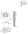
Vor dem Verschlussprofil ist im vorliegenden Ausführungsbeispiel, wie in Figur 9 gezeigt, jeweils eine Führungsschiene 40 angebracht, in der jeweils eine Führungsnut 42 ausgebildet ist. In dieser Führungsnut 42 sind nun vertikal flache Plättchen 20 eingelassen. Diese Plättchen 20 sind so ausgebildet, dass sie in der Führungsnut vertikal gleiten können. Sie weisen oben einen rechteckigen Ausschnitt 24 auf, in den die Schliesszungen 52 mit ihren zusätzlichen Erhöhungselementen aus den beiden Rampen 54 und 56 und dem flachen Teil 58 hindurch gefahren werden können, allerdings indem die beiden benachbarten Plättchen auseinander gedrückt werden. Im Ausführungsbeispiel ist auch an der Unterseite der Plättchen ein kleiner, rechteckiger Ausschnitt ausgebildet, der funktional mit dem oberen Ausschnitt 24 an dem darunter angeordneten Plättchen 20 wie vorstehend beschrieben zusammenwirkt. Das unterste Plättchen 20 liegt auf einen Verbindungselement 28 auf, mit dem die beiden Führungsschienen 40 verbunden sind. Beim Auseinanderdrücken der Plättchen 20 kann also nur das Plättchen 20 oberhalb der mit dem Erhöhungselement ausgebildeten Schliesszunge 52 nach oben bewegt werden. Dies ist wegen der vertikalen Aufeinanderreihung der Plättchen 20 nur möglich, wenn auch alle über dem genannten Plättchen 20 befindlichen Plättchen nach oben gleiten. Der hier beschriebene Ruhezustand mit eingefahrenen Schubladen 12 ist insbesondere in Figur 7 dargestellt.In front of the closure profile, in the present exemplary embodiment, as shown in FIG. 9, a
Oben sind die Führungsschienen 40 ebenfalls mit einem Verbindungselement 26 verbunden, welches zusätzlich als oberes Begrenzungselement der Bewegung der Plättchen 20 ausgebildet ist. Der Abstand des obersten Plättchens 20 im Zustand, in dem alle Plättchen 20 aufeinander liegen und durch keine Schliesszunge 52 nach oben bewegt wird, vom oberen Verbindungs- und Begrenzungselement 26 ist gerade so ausgewählt, dass nur ein Erhöhungselement bezüglich seines flachen Teils 58 transient durch die aufeinander gereihten Plättchen 20 hindurchpasst. Befindet sich der flache Teil 58 eines Erhöhungselementes in einer Öffnung 24 zwischen zwei Plättchen 20, so liegt das oberste Plättchen gerade am oberen Verbindungs- und Begrenzungselement 26 an. Ein weiteres Anheben der Plättchen 20 ist in diesem Zustand nicht möglich, so dass eine weitere Schublade 12 nicht ausgezogen werden kann. Diese Funktion ist insbesondere in Figur 8 dargestellt.Above the guide rails 40 are also connected to a connecting element 26 which is additionally formed as an upper delimiting element of the movement of the
Um die transiente Auszugsicherung beim Beginn des Auszugs der Schubladen wirksam zu machen, ist die vordere Rampe 54 auf der Schliesszunge 52 so angeordnet, dass sie bei vollständig eingefahrener Schublade 12 eben noch an dem zugeordneten oberen Plättchen anliegt. Durch diese Ausgestaltung wird nämlich bewirkt, dass schon bei einer kleinen Auszugbewegung der Schublade 12 der beschriebene Bewegungsvorgang des oberen Plättchens und aller darüber liegenden Plättchen beginnt oder verhindert wird.In order to make the transient pull-out protection effective at the beginning of the drawer extension, the front ramp 54 is arranged on the closing
Wenn die ausgezogene Schublade über einen bestimmten Öffnungsweg hin ausgezogen wurde, so senken sich die Plättchen 20, die oberhalb der Schliesszunge angeordnet sind, wieder ab und der zusätzliche Schliessmechanismus wirkt nicht weiter. Das Absenken ist durch die Position der hinteren Rampe 56 definiert. Wenn also die entsprechende Schublade 12 über einen bestimmten Auszugweg hinaus ausgezogen wurde, so wirkt im vorliegenden Ausführungsbeispiel nur noch die Auszugsicherung gemäss dem Stand der Technik, wie sie z.B. in der WO-A-96/25577 und auch in der EP-A-1 035 285 offenbart ist. Es muss aber betont werden, dass die zusätzliche, transiente Auszugsicherung gemäss der vorliegenden Erfindung mit jeder anderen Auszugsicherung zusammenwirken kann.When the drawer drawer has been pulled out over a certain opening way, the
Durch eine besondere Massnahme der Erfindung wirkt die transiente Auszugsicherung gemäss der vorliegenden Erfindung aber noch in einem weiteren Sinne sichernd. Die Plättchen 20 sind nämlich so angeordnet, dass jeweils ein Plättchen 20 den Zwischenraum zwischen zwei Schubladen 12 schützt. Damit wird verhindert, dass an dem Schliessmechanismus 26, 27 mit einem Gegenstand, der zwischen zwei eingefahrenen Schubladen 12 hindurch geführt wird, manipuliert werden kann. Im vorliegenden Ausführungsbeispiel ist also die Öffnung 24 eines Plättchens immer durch die Schublade abgedeckt und zwar sowohl im unteren, ruhenden Zustand als auch im angehobenen Zustand. Im vorliegenden Ausführungsbeispiel ist dieser Sachverhalt dadurch gewährleistet, dass die Gesamthöhe eines einzelnen Plättchens 20 mit 25 mm bemessen wird, während die Öffnung 24 zusammen mit dem - im Ausführungsbeispiel kleinen unteren Ausschnitt an den Plättchen 20 nicht mehr als 5 - 8 mm, entsprechend der Höhe des flachen Teils 58 auf der Schliesszunge 52 beträgt, so dass der verdeckende Teil des Plättchens 20 sowohl im angehobenen als auch im abgesenkten Zustand immer schützend vor dem durch den Zwischenraum zwischen zwei Schubladen zugänglichen Teil der Schliessleiste liegt.By a special measure of the invention, the transient pull-out protection according to the present invention, however, still acts in a wider sense. The
Im vorliegenden Ausführungsbeispiel ist die zusätzliche, transiente Auszugssicherung modular so aufgebaut, dass sie beim Einsetzen verschiedener Schubladen 12 in den Schubladenschrank 10 nicht verändert oder angepasst werden muss. Wie schon beschrieben, beträgt die Höhe eines Plättchens im Ausführungsbeispiel 25 mm. Dadurch ist der modulare Einsatz von Schubladen mit einer Höhe von beispielsweise 25 mm, 50 mm, 75 mm 100 mm oder einem weiteren Vielfachen von 25 mm möglich, ohne die Auszugssicherung in irgendeiner Weise anpassen zu müssen. Da auch der Schliessmechanismus gemäss dem Stand der Technik nach der WO-A-96/25577 und auch nach der EP-A-1 035 285 verschiedene Schubladenhöhen zulässt, ist eine, bezüglich der Sicherung optimale Anpassung verschiedener Schubladenarten möglich.In the present embodiment, the additional, transient pull-out protection is modularly constructed such that it when inserting
Claims (8)
- A slide safety assembly for a drawer cabinet- with a multiplicity of movable elements disposed essentially in a row (20),- a guide means (40) for guiding the movable elements disposed essentially in a row (20),- adjusting elements (50) that can be brought into contact with the drawers that are to be secured (12) for adjusting the vertical position of the movable elements disposed essentially in a row (20),- a limiting means (26) for limiting the movability of the movable elements disposed essentially in a row (20), wherein- the adjusting elements (50) can be brought into working contact with the drawers that are to be secured (12) such that when one of the drawers to be secured (12) starts to be pulled out they move one of the movable elements disposed essentially in a row (20) and all other elements located in one of the row directions (20), but once the drawer (12) being pulled out reaches a given pull-out position, they are moved back to the starting position by the gravitational and/or elastic force of a spring element and/or another driving means pushing back the movable elements disposed essentially in a row (20),characterised in that- the movable elements disposed essentially in a row (20) are in the form of essentially flat plates with an opening section (24),- the adjusting elements (50) are in the form of closing plates with a closing tongue (52), wherein the closing tongue has a ramp(54, 56) on each side of the slide movement of the drawer (12),- the guide means (40) is in the form of a guide rail, wherein the flat plates (20) are carried on each side along a guide channel(42) in the guide rail (40).
- The slide safety assembly according to claim 1, characterised in that there is an essentially flat part (58) between the aforementioned ramps (54, 56) on the closing tongue.
- The slide safety assembly according to one of the claims 1 to 2, characterised in that the movable elements disposed essentially in a row (20) are disposed essentially vertically.
- A drawer cabinet with several compartments separate from one another, preferably pull-out drawers (12), which are disposed in a cabinet housing, wherein each of these compartments can be locked and unlocked by a locking mechanism, a lock acting on the respective compartment is provided for the locking and unlocking of each of these compartments and the locking mechanism has a central locking profile, which comprises a single slide safety assembly, through which only one compartment can ever be opened at a time,
characterised in that
the drawer cabinet has, in addition, a slide safety assembly according to claims 1 to 3. - The cabinet according to claim 4, characterised in that locks can be actuated separately from one another, so that drawers can be released for sliding out independently of one another.
- The cabinet according to claim 4 or 5, characterised in that the locks can be actuated electrically.
- The cabinet according to one of the claims 4 to 6, characterised in that the aforementioned single slide safety assembly comprises two safety strips that act on all drawers in the cabinet, which can be transferred by one drawer (12) in each case from a lock position, in which they lock drawers (12) to prevent them from being pulled out, into a release position, in which a drawer can be pulled out.
- The cabinet according to claim 7, characterised in that the guide means (40) is disposed on the safety strip.
Applications Claiming Priority (2)
| Application Number | Priority Date | Filing Date | Title |
|---|---|---|---|
| CH234101 | 2001-12-21 | ||
| CH23412001 | 2001-12-21 |
Publications (3)
| Publication Number | Publication Date |
|---|---|
| EP1325995A2 EP1325995A2 (en) | 2003-07-09 |
| EP1325995A3 EP1325995A3 (en) | 2004-12-22 |
| EP1325995B1 true EP1325995B1 (en) | 2007-05-09 |
Family
ID=4568669
Family Applications (1)
| Application Number | Title | Priority Date | Filing Date |
|---|---|---|---|
| EP02406051A Expired - Lifetime EP1325995B1 (en) | 2001-12-21 | 2002-12-03 | Interlock device preventing the simultaneous opening of elements, in particular for a drawer cabinet |
Country Status (6)
| Country | Link |
|---|---|
| US (1) | US6966619B2 (en) |
| EP (1) | EP1325995B1 (en) |
| AT (1) | ATE362028T1 (en) |
| DE (1) | DE50210112D1 (en) |
| DK (1) | DK1325995T3 (en) |
| ES (1) | ES2299553T3 (en) |
Families Citing this family (8)
| Publication number | Priority date | Publication date | Assignee | Title |
|---|---|---|---|---|
| US20050178298A1 (en) * | 2004-01-20 | 2005-08-18 | Rossini Alfred P. | Mobile storage and computer cart |
| US20060197416A1 (en) * | 2005-03-02 | 2006-09-07 | Tung Chieh Industries Co., Ltd. | Locking control unit for tool box' drawers |
| ES2304106B1 (en) * | 2007-02-23 | 2009-05-01 | Ojmar S.A. | LOCK SYSTEM FOR FURNITURE DRAWERS. |
| US7823992B2 (en) * | 2007-12-19 | 2010-11-02 | King Slide Works Co., Ltd. | Drawer interlock mechanism |
| US8696074B2 (en) * | 2008-11-17 | 2014-04-15 | Andrew Romaen | Safety lock system for cabinet drawers |
| US8297723B2 (en) | 2011-01-21 | 2012-10-30 | King Slide Works Co., Ltd. | Interlock device for slide assembly |
| ITMO20130151A1 (en) * | 2013-05-28 | 2014-11-29 | Fami Srl | CLOSING SYSTEM FOR DRAWER CABINETS |
| CN111817194B (en) * | 2020-06-27 | 2022-04-05 | 宁波功成电气有限公司 | Drawer type switch cabinet |
Family Cites Families (8)
| Publication number | Priority date | Publication date | Assignee | Title |
|---|---|---|---|---|
| CH88353A (en) * | 1920-05-29 | 1921-07-01 | Ludin Hermann | Equipment at desks etc. |
| US3969008A (en) * | 1975-06-27 | 1976-07-13 | All-Steel Inc. | Safety latch and drawer movement sequencing control arrangement for file cabinets |
| US4804876A (en) * | 1987-04-16 | 1989-02-14 | Lyon Metal Products, Incorporated | Cabinet with latch mechanism |
| FR2699057B1 (en) * | 1992-12-11 | 1995-01-13 | Ronis Sa | Adjustable device for locking the drawers of a piece of furniture and piece of furniture equipped with such a device. |
| US5634701A (en) * | 1994-08-31 | 1997-06-03 | Fireking International, Inc. | Multi-drawer cabinet having a drawer lock-out mechanism |
| US5605388A (en) * | 1995-02-14 | 1997-02-25 | Lista International Corporation | Cabinet drawer interlocking system |
| US6296332B1 (en) * | 1996-07-12 | 2001-10-02 | Accuride International, Inc. | File interlock system and mechanism |
| US5671985A (en) * | 1996-08-27 | 1997-09-30 | Sauder Woodworking Co. | Drawer interlock assembly |
-
2002
- 2002-12-03 EP EP02406051A patent/EP1325995B1/en not_active Expired - Lifetime
- 2002-12-03 DE DE50210112T patent/DE50210112D1/en not_active Expired - Fee Related
- 2002-12-03 ES ES02406051T patent/ES2299553T3/en not_active Expired - Lifetime
- 2002-12-03 AT AT02406051T patent/ATE362028T1/en not_active IP Right Cessation
- 2002-12-03 DK DK02406051T patent/DK1325995T3/en active
- 2002-12-09 US US10/314,665 patent/US6966619B2/en not_active Expired - Fee Related
Also Published As
| Publication number | Publication date |
|---|---|
| ES2299553T3 (en) | 2008-06-01 |
| US20030127953A1 (en) | 2003-07-10 |
| DE50210112D1 (en) | 2007-06-21 |
| US6966619B2 (en) | 2005-11-22 |
| EP1325995A3 (en) | 2004-12-22 |
| EP1325995A2 (en) | 2003-07-09 |
| DK1325995T3 (en) | 2007-09-24 |
| ATE362028T1 (en) | 2007-06-15 |
Similar Documents
| Publication | Publication Date | Title |
|---|---|---|
| EP0785877B1 (en) | Locking device for vehicle seats | |
| DE2348998A1 (en) | DOOR UNLOCKING, IN PARTICULAR FOR EMERGENCY EXITS | |
| DE4408024C5 (en) | safety switch | |
| EP2133494B1 (en) | Safety lock device with escape locking device | |
| EP1325995B1 (en) | Interlock device preventing the simultaneous opening of elements, in particular for a drawer cabinet | |
| DE2349182A1 (en) | CYLINDER LOCK ARRANGEMENT | |
| DE4325920A1 (en) | Pull-out locking device for furniture drawers | |
| DE4315452A1 (en) | Locking arrangement for drawers - has arrangement of rods and catches such that all drawers are held closed or only one drawer may be opened | |
| DE102005054006B4 (en) | Pull-out safety device for drawers of furniture | |
| DE3512856C2 (en) | Armored door | |
| EP4229257A1 (en) | Sliding door | |
| EP0453626B1 (en) | Swivelling and submerging lever closure with lock device | |
| DE102008015655A1 (en) | panic lock | |
| EP1082232B1 (en) | Locking device | |
| DE19738244C2 (en) | Lock for security doors | |
| WO1995030974A1 (en) | Coin-operated lock | |
| DE4004724C1 (en) | Roller container for use in laboratories - has two steering rollers, two rollers which are stopped by foot pedal | |
| DE10124684C1 (en) | Pull-out system for cabinet drawers employs guide rail traveled by setting axis with control element per drawer fitted with opening and blocking slides. | |
| DE4434933C2 (en) | Lock for central locking and unlocking of drawers | |
| WO1991017333A1 (en) | Recessed pivoting lever closure fitted with a locking device | |
| DE3414642A1 (en) | Block lock | |
| EP0698707B1 (en) | Central locking device for tool carriage | |
| EP0641909A2 (en) | Padlock, with self-blocking dead locking of a bolt element | |
| EP3243985A1 (en) | Lock for a swivelling wing | |
| EP4229260A1 (en) | Locking device for movable furniture parts |
Legal Events
| Date | Code | Title | Description |
|---|---|---|---|
| PUAI | Public reference made under article 153(3) epc to a published international application that has entered the european phase |
Free format text: ORIGINAL CODE: 0009012 |
|
| AK | Designated contracting states |
Designated state(s): AT BE BG CH CY CZ DE DK EE ES FI FR GB GR IE IT LI LU MC NL PT SE SI SK TR |
|
| AX | Request for extension of the european patent |
Extension state: AL LT LV MK RO SI |
|
| PUAL | Search report despatched |
Free format text: ORIGINAL CODE: 0009013 |
|
| AK | Designated contracting states |
Kind code of ref document: A3 Designated state(s): AT BE BG CH CY CZ DE DK EE ES FI FR GB GR IE IT LI LU MC NL PT SE SI SK TR |
|
| AX | Request for extension of the european patent |
Extension state: AL LT LV MK RO |
|
| 17P | Request for examination filed |
Effective date: 20050506 |
|
| AKX | Designation fees paid |
Designated state(s): AT BE BG CH CY CZ DE DK EE ES FI FR GB GR IE IT LI LU MC NL PT SE SI SK TR |
|
| GRAP | Despatch of communication of intention to grant a patent |
Free format text: ORIGINAL CODE: EPIDOSNIGR1 |
|
| GRAS | Grant fee paid |
Free format text: ORIGINAL CODE: EPIDOSNIGR3 |
|
| GRAA | (expected) grant |
Free format text: ORIGINAL CODE: 0009210 |
|
| AK | Designated contracting states |
Kind code of ref document: B1 Designated state(s): AT BE BG CH CY CZ DE DK EE ES FI FR GB GR IE IT LI LU MC NL PT SE SI SK TR |
|
| PG25 | Lapsed in a contracting state [announced via postgrant information from national office to epo] |
Ref country code: FI Free format text: LAPSE BECAUSE OF FAILURE TO SUBMIT A TRANSLATION OF THE DESCRIPTION OR TO PAY THE FEE WITHIN THE PRESCRIBED TIME-LIMIT Effective date: 20070509 |
|
| REG | Reference to a national code |
Ref country code: GB Ref legal event code: FG4D Free format text: NOT ENGLISH |
|
| REG | Reference to a national code |
Ref country code: CH Ref legal event code: EP |
|
| REG | Reference to a national code |
Ref country code: IE Ref legal event code: FG4D Free format text: LANGUAGE OF EP DOCUMENT: GERMAN |
|
| REF | Corresponds to: |
Ref document number: 50210112 Country of ref document: DE Date of ref document: 20070621 Kind code of ref document: P |
|
| PG25 | Lapsed in a contracting state [announced via postgrant information from national office to epo] |
Ref country code: SE Free format text: LAPSE BECAUSE OF FAILURE TO SUBMIT A TRANSLATION OF THE DESCRIPTION OR TO PAY THE FEE WITHIN THE PRESCRIBED TIME-LIMIT Effective date: 20070809 |
|
| GBT | Gb: translation of ep patent filed (gb section 77(6)(a)/1977) |
Effective date: 20070816 |
|
| ET | Fr: translation filed | ||
| RAP2 | Party data changed (patent owner data changed or rights of a patent transferred) |
Owner name: LISTA B + L HOLDING AG |
|
| PG25 | Lapsed in a contracting state [announced via postgrant information from national office to epo] |
Ref country code: PT Free format text: LAPSE BECAUSE OF FAILURE TO SUBMIT A TRANSLATION OF THE DESCRIPTION OR TO PAY THE FEE WITHIN THE PRESCRIBED TIME-LIMIT Effective date: 20071009 Ref country code: BG Free format text: LAPSE BECAUSE OF FAILURE TO SUBMIT A TRANSLATION OF THE DESCRIPTION OR TO PAY THE FEE WITHIN THE PRESCRIBED TIME-LIMIT Effective date: 20070809 Ref country code: SI Free format text: LAPSE BECAUSE OF FAILURE TO SUBMIT A TRANSLATION OF THE DESCRIPTION OR TO PAY THE FEE WITHIN THE PRESCRIBED TIME-LIMIT Effective date: 20070509 |
|
| NLT2 | Nl: modifications (of names), taken from the european patent patent bulletin |
Owner name: LISTA B + L HOLDING AG Effective date: 20071219 |
|
| PLBE | No opposition filed within time limit |
Free format text: ORIGINAL CODE: 0009261 |
|
| STAA | Information on the status of an ep patent application or granted ep patent |
Free format text: STATUS: NO OPPOSITION FILED WITHIN TIME LIMIT |
|
| 26N | No opposition filed |
Effective date: 20080212 |
|
| PG25 | Lapsed in a contracting state [announced via postgrant information from national office to epo] |
Ref country code: GR Free format text: LAPSE BECAUSE OF FAILURE TO SUBMIT A TRANSLATION OF THE DESCRIPTION OR TO PAY THE FEE WITHIN THE PRESCRIBED TIME-LIMIT Effective date: 20070810 Ref country code: IT Free format text: LAPSE BECAUSE OF NON-PAYMENT OF DUE FEES Effective date: 20071203 |
|
| PGFP | Annual fee paid to national office [announced via postgrant information from national office to epo] |
Ref country code: DE Payment date: 20080228 Year of fee payment: 6 |
|
| REG | Reference to a national code |
Ref country code: ES Ref legal event code: FG2A Ref document number: 2299553 Country of ref document: ES Kind code of ref document: T3 |
|
| BERE | Be: lapsed |
Owner name: LISTA EUROPE HOLDING A.G. Effective date: 20071231 |
|
| PGFP | Annual fee paid to national office [announced via postgrant information from national office to epo] |
Ref country code: AT Payment date: 20080314 Year of fee payment: 6 |
|
| PG25 | Lapsed in a contracting state [announced via postgrant information from national office to epo] |
Ref country code: MC Free format text: LAPSE BECAUSE OF NON-PAYMENT OF DUE FEES Effective date: 20071231 Ref country code: CZ Free format text: LAPSE BECAUSE OF NON-PAYMENT OF DUE FEES Effective date: 20071203 |
|
| REG | Reference to a national code |
Ref country code: DK Ref legal event code: EBP |
|
| GBPC | Gb: european patent ceased through non-payment of renewal fee |
Effective date: 20071203 |
|
| NLV4 | Nl: lapsed or anulled due to non-payment of the annual fee |
Effective date: 20080701 |
|
| PG25 | Lapsed in a contracting state [announced via postgrant information from national office to epo] |
Ref country code: BE Free format text: LAPSE BECAUSE OF NON-PAYMENT OF DUE FEES Effective date: 20071231 |
|
| PG25 | Lapsed in a contracting state [announced via postgrant information from national office to epo] |
Ref country code: IE Free format text: LAPSE BECAUSE OF NON-PAYMENT OF DUE FEES Effective date: 20071203 Ref country code: SK Free format text: LAPSE BECAUSE OF NON-PAYMENT OF DUE FEES Effective date: 20071203 |
|
| REG | Reference to a national code |
Ref country code: CH Ref legal event code: PUE Owner name: LISTA B+L HOLDING AG Free format text: LISTA EUROPE HOLDING AG#FABRIKSTRASSE 1#8586 ERLEN (CH) -TRANSFER TO- LISTA B+L HOLDING AG#FABRIKSTRASSE 1#8586 ERLEN (CH) |
|
| REG | Reference to a national code |
Ref country code: FR Ref legal event code: ST Effective date: 20081020 |
|
| PG25 | Lapsed in a contracting state [announced via postgrant information from national office to epo] |
Ref country code: NL Free format text: LAPSE BECAUSE OF NON-PAYMENT OF DUE FEES Effective date: 20080701 |
|
| PG25 | Lapsed in a contracting state [announced via postgrant information from national office to epo] |
Ref country code: GB Free format text: LAPSE BECAUSE OF NON-PAYMENT OF DUE FEES Effective date: 20071203 |
|
| PG25 | Lapsed in a contracting state [announced via postgrant information from national office to epo] |
Ref country code: DK Free format text: LAPSE BECAUSE OF NON-PAYMENT OF DUE FEES Effective date: 20080102 Ref country code: EE Free format text: LAPSE BECAUSE OF FAILURE TO SUBMIT A TRANSLATION OF THE DESCRIPTION OR TO PAY THE FEE WITHIN THE PRESCRIBED TIME-LIMIT Effective date: 20070509 |
|
| REG | Reference to a national code |
Ref country code: ES Ref legal event code: FD2A Effective date: 20071204 |
|
| PG25 | Lapsed in a contracting state [announced via postgrant information from national office to epo] |
Ref country code: FR Free format text: LAPSE BECAUSE OF NON-PAYMENT OF DUE FEES Effective date: 20071231 Ref country code: ES Free format text: LAPSE BECAUSE OF NON-PAYMENT OF DUE FEES Effective date: 20071204 |
|
| PG25 | Lapsed in a contracting state [announced via postgrant information from national office to epo] |
Ref country code: CY Free format text: LAPSE BECAUSE OF FAILURE TO SUBMIT A TRANSLATION OF THE DESCRIPTION OR TO PAY THE FEE WITHIN THE PRESCRIBED TIME-LIMIT Effective date: 20070509 |
|
| PG25 | Lapsed in a contracting state [announced via postgrant information from national office to epo] |
Ref country code: AT Free format text: LAPSE BECAUSE OF NON-PAYMENT OF DUE FEES Effective date: 20081203 Ref country code: LU Free format text: LAPSE BECAUSE OF NON-PAYMENT OF DUE FEES Effective date: 20071203 |
|
| PG25 | Lapsed in a contracting state [announced via postgrant information from national office to epo] |
Ref country code: TR Free format text: LAPSE BECAUSE OF FAILURE TO SUBMIT A TRANSLATION OF THE DESCRIPTION OR TO PAY THE FEE WITHIN THE PRESCRIBED TIME-LIMIT Effective date: 20070509 |
|
| PG25 | Lapsed in a contracting state [announced via postgrant information from national office to epo] |
Ref country code: DE Free format text: LAPSE BECAUSE OF NON-PAYMENT OF DUE FEES Effective date: 20090701 |
|
| REG | Reference to a national code |
Ref country code: CH Ref legal event code: PFA Owner name: LISTA AG Free format text: LISTA B+L HOLDING AG#FABRIKSTRASSE 1#8586 ERLEN (CH) -TRANSFER TO- LISTA AG#FABRIKSTRASSE 1#8586 ERLEN (CH) |
|
| REG | Reference to a national code |
Ref country code: CH Ref legal event code: PL |
|
| REG | Reference to a national code |
Ref country code: CH Ref legal event code: AECN Free format text: DAS PATENT IST AUFGRUND DES WEITERBEHANDLUNGSANTRAGS VOM 08.08.2013 REAKTIVIERT WORDEN. |
|
| PGFP | Annual fee paid to national office [announced via postgrant information from national office to epo] |
Ref country code: CH Payment date: 20141106 Year of fee payment: 13 |
|
| REG | Reference to a national code |
Ref country code: CH Ref legal event code: PL |
|
| PG25 | Lapsed in a contracting state [announced via postgrant information from national office to epo] |
Ref country code: LI Free format text: LAPSE BECAUSE OF NON-PAYMENT OF DUE FEES Effective date: 20151231 Ref country code: CH Free format text: LAPSE BECAUSE OF NON-PAYMENT OF DUE FEES Effective date: 20151231 |