EP0640906A2 - Anzeigegerät - Google Patents
Anzeigegerät Download PDFInfo
- Publication number
- EP0640906A2 EP0640906A2 EP94113067A EP94113067A EP0640906A2 EP 0640906 A2 EP0640906 A2 EP 0640906A2 EP 94113067 A EP94113067 A EP 94113067A EP 94113067 A EP94113067 A EP 94113067A EP 0640906 A2 EP0640906 A2 EP 0640906A2
- Authority
- EP
- European Patent Office
- Prior art keywords
- display
- shape
- displayed
- designated
- designating
- Prior art date
- Legal status (The legal status is an assumption and is not a legal conclusion. Google has not performed a legal analysis and makes no representation as to the accuracy of the status listed.)
- Granted
Links
Images


Classifications
-
- G—PHYSICS
- G06—COMPUTING OR CALCULATING; COUNTING
- G06T—IMAGE DATA PROCESSING OR GENERATION, IN GENERAL
- G06T19/00—Manipulating 3D models or images for computer graphics
-
- G—PHYSICS
- G06—COMPUTING OR CALCULATING; COUNTING
- G06F—ELECTRIC DIGITAL DATA PROCESSING
- G06F3/00—Input arrangements for transferring data to be processed into a form capable of being handled by the computer; Output arrangements for transferring data from processing unit to output unit, e.g. interface arrangements
- G06F3/01—Input arrangements or combined input and output arrangements for interaction between user and computer
- G06F3/048—Interaction techniques based on graphical user interfaces [GUI]
- G06F3/0484—Interaction techniques based on graphical user interfaces [GUI] for the control of specific functions or operations, e.g. selecting or manipulating an object, an image or a displayed text element, setting a parameter value or selecting a range
- G06F3/04845—Interaction techniques based on graphical user interfaces [GUI] for the control of specific functions or operations, e.g. selecting or manipulating an object, an image or a displayed text element, setting a parameter value or selecting a range for image manipulation, e.g. dragging, rotation, expansion or change of colour
-
- G—PHYSICS
- G06—COMPUTING OR CALCULATING; COUNTING
- G06F—ELECTRIC DIGITAL DATA PROCESSING
- G06F30/00—Computer-aided design [CAD]
- G06F30/10—Geometric CAD
-
- G—PHYSICS
- G06—COMPUTING OR CALCULATING; COUNTING
- G06F—ELECTRIC DIGITAL DATA PROCESSING
- G06F30/00—Computer-aided design [CAD]
-
- Y—GENERAL TAGGING OF NEW TECHNOLOGICAL DEVELOPMENTS; GENERAL TAGGING OF CROSS-SECTIONAL TECHNOLOGIES SPANNING OVER SEVERAL SECTIONS OF THE IPC; TECHNICAL SUBJECTS COVERED BY FORMER USPC CROSS-REFERENCE ART COLLECTIONS [XRACs] AND DIGESTS
- Y10—TECHNICAL SUBJECTS COVERED BY FORMER USPC
- Y10S—TECHNICAL SUBJECTS COVERED BY FORMER USPC CROSS-REFERENCE ART COLLECTIONS [XRACs] AND DIGESTS
- Y10S715/00—Data processing: presentation processing of document, operator interface processing, and screen saver display processing
- Y10S715/961—Operator interface with visual structure or function dictated by intended use
- Y10S715/964—CAD or CAM, e.g. interactive design tools
Definitions
- This invention relates to a display apparatus and display control method used in, say, a CAD (computer aided design) system utilized when designing machines or the like.
- CAD computer aided design
- any desired part shape on the display of a CAD system capable of displaying a plurality of parts is desired to be hidden or removed from the display
- one method used in the prior art is to designate the part name or group name of the part using a keyboard or mouse.
- Another method is to directly designate a displayed part on the display screen using a pointing device such as a mouse, thereby hiding the designated part shape.
- the part name or group name is designated by a mouse or keyboard, thereby causing the designated part to be shown again.
- an object of the present invention is to provide a display apparatus and display control method through which members under display control can be specified intuitively.
- Another object of the present invention is to provide a display apparatus and display control method through which a specific member is designated from among displayed members and an identifier is displayed instead of the shape of the designated member, thereby making it possible to grasp intuitively the position of a member that has been hidden from view.
- Another object of the present invention is to provide a display apparatus and display control method through which a specific member is designated from among displayed members, an identifier is displayed instead of the shape of the designated member and, when display of the shape of a member that has been hidden is to be resumed, the identifier is designated to again show the the shape of this member.
- a further object of the present invention is to provide a display apparatus which allows the operator to designate part of the displayed shape of a target member from among a plurality of displayed members, whereby it is possible to temporarily stop displaying the shape of this member.
- Yet another object of the present invention is to provide a display apparatus and display control method in which, when a member that has already been hidden is to be shown again, allow the operator to readily grasp the position of the hidden member.
- Fig. 2 is a block diagram illustrating the construction of a CAD system used in first and second embodiments to which the shape method of the present invention is applied.
- the CAD system includes a central processing unit 2, a display unit 4, an input unit 6, a memory device 8 and an information reading unit 10. These will now be described in detail.
- CAD system displays the layout of the parts of a certain assembly.
- the CAD system can of course be applied also to a display of figures for other purposes.
- the figures displayed are referred to as "parts" for descriptive purposes.
- the central processing unit 2 executes a plurality of processing operations, described later, in addition to processing for displaying shapes.
- the display unit 4 displays two- and three-dimensional images corresponding to part shapes, icons which are pictorial characters or the like representing identifiers such as part names, and menus for designating whether parts are to be shown or hidden.
- the input unit 6, which has a keyboard and a pointing device such as a mouse, is used to enter information necessary for showing or hiding part shapes, to make menu selections and enter various commands.
- the memory device 8 stores a program for displaying shapes, described below, as well as two- and three-dimensional shape data representing parts.
- the information reading unit 10 reads in the shape-display program from an external unit and stores the program in the memory device 8.
- a program is read in a semiconductor RAM or in the memory device 8, which uses a magnetic disk or the like, from an external storage medium such as a magnetic tape or floppy disk through the information reading unit 10.
- Two- or three-dimensional shapes are displayed on the display unit 4, and data representing the two or three-dimensional shapes is stored in the memory device 8.
- the selection of menus necessary for displaying shapes as well as the selection of parts is performed by the input unit 6.
- the shape of a designated part or the like is hidden from view and replaced by an icon displayed on the display unit 4.
- Two- or three-dimensional shapes of hidden parts in the vicinity of parts or positions that have been designated are re-displayed on the display unit 4.
- a two-dimensional shape is comprised of two-dimentional graphic elements such as points, straight line segments, circles, arcs, Spline curves, hyperbolas, parabolas, and series of straight line segments.
- the elements are expressed by two components (x, y) in the case of a Cartesian coordinate system.
- two-dimentional shape is displayed, hidden, removed, moved and/or copied in a group basis which comprises a set of two-dimentional graphic elements which are related to each other.
- Three-dimensional shape is comprised of three-dimentional graphic elements such as points, straight line segments, circles, arcs, Spline curves, hyperbolas, parabolas, series of straight line segments, three-dimensional planes, cylindrical surfaces, conical surfaces, spherical surfaces and other curved surfaces expressed parametrically.
- the elements are expressed by three components (x, y, z) in the case of a Cartesian coordinate system.
- the three-dimensional figure elements can be displayed and hidden and subjected to such operations as deletion, moving and copying in individual units or as single groups composed of a set of elements having cohesiveness, such as the shape of a part or the like. For descriptive purposes, one group shall be referred to as an "object".
- Displaying a three-dimensional shape means regarding one two-dimensional plane defined based upon point of sight as one projection screen, projecting the three-dimensional shape of interest on the projection screen employing the normal-line direction of this three-dimensional plane as the projection direction, and displaying the result on the display unit 4.
- portions concealed at the time of projection are hidden (not displayed) upon taking the hierarchical relationship into account, and shading (shadowing) can be applied upon referring to light-source information set in advance with regard to the plane as seen from the projection direction.
- the display unit 4 displays two-dimensional shapes or three-dimensional shapes, which have been projected upon the projection screen, upon performing enlargement or reduction over a limited range.
- the central processing unit 2 clips the shapes displayed on the display unit from the shapes to be displayed and then displays the results on the display unit 4.
- the means for setting the above-mentioned projection screen, the means for projecting the three-dimensional shapes on the projection screen, the means for creating shapes to be displayed from what is projected upon the projection screen and from two-dimensional figures, and the means for displaying the created shapes on the display unit 4 are well-known in the art.
- This embodiment is provided with these means and the expression "display of shapes” mentioned below means that the embodiment is implemented using these means.
- Step 1 in Fig. 1 is for selecting an item "HIDE" from a menu in order not to display the shape of a part or the like. This is accomplished by using a mouse to designate a "HIDE" menu 22 displayed on the display unit 4 in Fig. 3A.
- a menu for hiding shapes can be assigned to a specific key on a keyboard or command box in advance. By pressing the key to which the menu is assigned, an operation for "hiding" a shape can be initiated.
- the operator uses the input unit 6 such as a mouse to specify a part or the like that is to be hidden from among parts displayed on the display unit 4. It is also possible to designate a part to be hidden by entering the identifier of the part name using the input unit 6 such as the keyboard.
- the input unit 6 such as a mouse
- the central processing unit 2 When a part to be hidden from view is designated, the central processing unit 2 causes an icon (identifier) or the like to be displayed for the part designated to be hidden at step 3.
- step 3 the shape of a part designated to be hidden is erased from the display unit 4 and in its place an icon 24 of the kind shown in Fig. 3C is displayed on the display unit 4.
- means for setting whether the icon 24 is to be shown or hidden is provided in advance.
- a designation for not displaying a part or the like has been made in a case where a mode for hiding (not displaying) the icon 24 has been set, the shape of the part or the like designated to be hidden is erased from the display unit 4 and the substitution icon also is not displayed.
- the arrangement is such that icons are displayed if no particular designation is made (this represents a default setting).
- the icon 24 such as a pictorial character is displayed in place of a shape that has been hidden from view.
- layout processing therefore, the operator is capable of readily ascertaining that a part has been hidden. As a result, layout processing is made more efficient and reliable.
- a part name or the like may be displayed instead of an icon.
- step 2 by executing step 2 again immediately after step 3, part shapes desired to be hidden one after another can be designated and then hidden from view.
- a flowchart illustrated in Fig. 4A is for describing the details of a method of setting the display position of an icon in a case where a part designated to be hidden at step 3 is displayed in the form of an icon.
- the centroid of the shape of a part designated to be hidden is calculated by the central processing unit 2, which refers to shape data stored in the memory device 8.
- the central processing unit 2 which refers to shape data stored in the memory device 8.
- an icon serving as an identifier is displayed at the position of the centroid.
- the reason for displaying the icon at the position of the centroid is that the centroid position is visually the most natural position for displaying the icon as far as the operator is concerned.
- centroid position serving as the position at which the icon is displayed need not be calculated with an especially high degree of accuracy.
- the centroid position is calculated approximately by the method described below.
- FIG. 4B A case in which the display unit 4 displays a two-dimensional shape will described with reference to Fig. 4B. If, in a case where the centroid position of a two-dimensional shape is calculated, the outer peripheral line of this shape is a closed loop, the outer peripheral line is approximated by a polygon (triangles ABE, BDE and BCD in Fig. 4B) and the centroid of this polygon is found.
- the method of determining the centroid of a polygon is well known.
- any vertex of the polygon is adopted as a datum point
- this polygon is divided into a plurality of triangles composed of the datum point and the starting and end points of each side of the polygon, and the centroid (G) of the overall polygon is obtained from the centroids (G i ) of these triangles.
- G and G i represent two-dimensional vectors and s i represents the area of each triangle.
- the subscript i indicates each triangle.
- the mid-point (P i ) of each element constructing the shape is found and the centroid (G) is obtained as follows from the length (d i ) of each of these elements: where G and P i represent two-dimensional vectors and the subscript i represents the element.
- centroid position of a three-dimensional shape is calculated, the three-dimensional shape is approximated by a polyhedron (a tetrahedron ABED and a tetrahedron ABCD) and the centroid of the polyhedron is found.
- the centroid of a polyhedron is found through the following procedure:
- one appropriate vertex of the polyhedron is selected as a datum point.
- the polyhedron is divided into a plurality of tetrahedrons which contain this datum point.
- the centroid (G i ) and volume (v i ) of each tetrahedron are obtained and the overall centroid (G) is obtained as follows: where G and G i represent three-dimensional vectors and v i the volume of each tetrahedron.
- the subscript i represents each tetrahedron.
- the icon 24 is displayed as shown in Fig. 3C in the vicinity of a position on the display unit 4 corresponding to the centroid position calculated at step 11.
- Substituting the display of an icon for the display of a part is convenient when the part is to be designated to restore the display thereof when such restoration is desired. If there are at least two parts hidden from view, it is difficult with the prior-art technique to designate one of the parts when only display of this part is desired to be restored, the reason being that the shapes of these parts cannot be seen. With this embodiment, however, the icons of the parts are displayed, thereby making it easy to designate the desired part.
- the flowchart of Fig. 5 illustrates a control procedure for resuming display of the shape of a part in a case where an icon is being displayed instead of the shape of the part.
- a "SHOW" item in the menu 22 being displayed on the display unit 4 is designated via the input unit 6, as shown in Fig. 6A.
- Figs. 6A through 6C are for describing the manner in which the progress of the operations shown in the flowchart of Fig. 5 is displayed on the display unit 4. It should be noted that a menu for instructing to display shapes can be assigned to a specific key on a keyboard or command box in advance. By pressing the key to which the menu is assigned, a menu for showing a shape can be selected.
- the operator uses the input unit 6 such as the mouse to designate the icon 24 being displayed on the display unit 4.
- icons are displayed in conformity with the number of parts hidden from view.
- identifiers such as part names of parts desired to be displayed can also be designated by the input unit 6 such as the keyboard or mouse. If an icon corresponding to a part shape desired to be shown is selected, the central processing unit 2 executes display of the shape of the part corresponding to the icon 24 selected at step 23.
- step 23 the shape of a designated part or the like is caused to be displayed on the display unit 4, as indicated at 26 in Fig. 6C.
- the icon 24 vanishes from the display unit 4 at this time.
- step 22 again immediately after step 23 makes it possible to successively designate icons 24 corresponding to part shapes desired to be shown and to show the shapes one after another.
- the shape of a part that has been hidden from view can be shown by designating a displayed icon. This makes it possible for the operator to operate the apparatus intuitively without being aware of identifiers such as part names.
- a hidden part can be displayed again by an intuitive operation even in a case where an icon serving as an identifier is not being displayed.
- a "SHOW" item in the menu 22 being displayed on the display unit 4 in Fig. 8A is designated by the operator via the input unit 6.
- Figs. 8A through 8C are for describing the manner in which the progress of the operations shown in the flowchart of Fig. 7A is displayed on the display unit 4. It should be noted that a menu for instructing to display shapes can be assigned to a specific key on a keyboard or command box in advance. By pressing the key to which the menu is assigned, a menu for showing a shape can be selected.
- step 32 calls for the operator to use the input unit 6 such as the mouse to designate the proximity of a position at which the operator believes the shape of the hidden part desired to be displayed will appear.
- the relevant information is stored in the memory device 8 and, at step 33, the central processing unit 2 causes the hidden part to be displayed in the vicinity of the position designated.
- the central processing unit 2 searches for a part in the vicinity of the position designated and finds a part, which is not currently being displayed, at a position closest to the designated position.
- the shape of the part thus found is caused to be displayed on the display unit 4, as indicated at 28 in Fig. 8C.
- means for setting the range of the search are provided. These means set the limits of the search in advance and store them in the memory device 8. If no particular search range is set, predetermined default values are adopted as the search limits.
- a search circle is set.
- the center of the circle is a designated position (this position is obtained at step 32), and the radius of the circle is the set search range.
- the central processing unit 2 judges whether there is a part intersected or surrounded by the search circle. If the result of the search is that there is a hidden part intersected or surrounded by the search circle, it is decided that the part is one to be re-displayed. If a plurality of hidden parts are intersected or surrounded by the search circle, then all of these shapes are caused to be displayed on the display unit 4.
- a search cylinder is set. As shown in Fig. 7C, the central axis of the cylinder is an axis extending in the projection direction from a designated position, and the radius of the cylinder is the set search range. While referring to the shape data and other data stored in the memory device 8, the central processing unit 2 judges whether there is a part intersected or surrounded by the search cylinder. If the result of the search is that there is a hidden part intersected or surrounded by the search cylinder, it is decided that the part is one to be re-displayed on the display unit 4. Theoretically, the search cylinder is one having an infinite length. If a plurality of hidden parts are intersected or surrounded by the search cylinder, then all of them are caused to be displayed on the display unit 4.
- step 32 again immediately after step 33 makes it possible to successively designate the positions of shapes of parts desired to be shown and to show the shapes one after another.
- a part that has been hidden from view can be displayed by an intuitive operation even if an icon corresponding to the shape of this hidden part is not being displayed.
- the second embodiment which is premised on use of a pointing device such as a mouse, is characterized by the ease with which the "object" (namely the shape of a part) designated by the mouse is designated.
- the functions established to achieve this are essentially the same as those of the first embodiment.
- Fig. 9A illustrates a menu set in the second embodiment.
- a "SHOW” item is designated to display an object
- a "HIDE” item is designated to inhibit display of an item (and to hide the identifier as well)
- a "CHANGE” item is designated to change the display of an object to the display of an icon representing the object.
- the "HIDE" menu of the first embodiment corresponds to the "HIDE” and "CHANGE” menus of the second embodiment.
- the hardware of the second embodiment is essentially the same as that of the first embodiment (Fig. 2).
- the composition of the software programs used in the second embodiment is shown in Fig. 9B. These programs are provided in the memory device 8.
- the second embodiment is so adapted that the particular object located at a position designated by the operator using a mouse is detected by a map referred to as an "object map".
- the map is provided in a prescribed area (Fig. 9B) of the memory device 8 of Fig. 2 and is capable of being accessed by the processing unit 2.
- Fig. 10 illustrates an example of the map.
- the map has a space whose size is the same as that of the display screen of display unit 4 and a depth such that all identifiers of objects to be displayed can be specified.
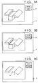
- the projections of the individual objects become three closed areas 50, 51, 52, as illustrated in Fig. 20.
- the object 30 does not overlap the other objects but a part of the object 31 is concealed by a part of the object 32.
- a method of creating such a projection diagram is well known. If the object 30 is registered first, then the object 31 and finally the object 32, then identification numbers ("object IDs") "1", "2” and “3” are assigned to these objects in the order mentioned. Data "1" is written at all addresses corresponding to the area 50 in the object map, data "2” is written at all addresses corresponding to the area 51, and data "3" is written at all addresses corresponding to area 52.
- Position 35 in Fig. 10 is a position at which the object 31 and object 32 overlap each other.
- Fig. 11 illustrates an object map representing the state of the display shown in Fig. 3C.
- the object 31 is displayed instead of the icon 24 corresponding to object 31.
- Fig. 12 illustrates a table for managing the painting of objects. This table also is provided in a prescribed area (Fig. 9B) of the memory device shown in Fig. 2 and is capable of being accessed by the processing unit 2.
- the management table is provided with an entry for each object ID. In the example of Fig. 12, four entries are established for respective ones of the four objects shown in Fig. 11.
- a field GDP(i) stores a pointer which points to figure data of object i.
- the figure data is stored in a vector format.
- the vector data is composed of two-dimensional points, two-dimensional line segments, two-dimensional circles, two-dimensional circular arcs, two-dimensional spline curves, two-dimensional hyperbolas, two-dimensional parabolas, two-dimensional line-segment sequences, three-dimensional points, three-dimensional line segments, three-dimensional circles, three-dimensional circular arcs, three-dimensional spline curves, three-dimensional hyperbolas, three-dimensional parabolas and three-dimensional line-segment sequences.
- the processing unit 2 paints the object based upon the vector data at this pointer in accordance with the paint program.
- a flag IDF(i) indicates whether shape data of an icon corresponding to an object i has already been generated. If an object for which shape data of an icon has not been created is replaced by display of an icon (i.e., if the menu item "CHANGE" has been designated), a icon generation program (see Fig. 9B) of the processing unit 2 reduces the image data of the object i, whereby the shape data of the icon is generated in the form of a bitmap. An icon can also be created by the operator.
- the storage location of the shape data of an icon created or already registered is stored at the pointer IDP(i).
- shape data of the icons of objects whose object IDs are 1, 2 and 3 have been stored at addresses "ddd”, "eee” and "fff", respectively.
- WP(i) stores the position of the centroid of object i.
- the method of deciding the centroid position is the same as described in the first embodiment.
- the centroids of objects whose object IDs are 1, 2 and 3 are calculated as AD1, AD2 and AD3, respectively.
- Centroid position is represented by the relative position of the object with respect to a prescribed datum point.
- the datum point is represented by absolute position in the display space of the display unit 4.
- editing frequently is performed by moving or rotating an object. If the shape of the object is not altered, the centroid position will not move in relative terms even if the object is moved or rotated. Once centroid position has been calculated, unnecessary repetitive calculation of centroid position is prevented by setting the corresponding flag WPF.
- the flag IF(i) indicates whether the object is an ordinary object or an icon object.
- Fig. 13 is a flowchart illustrating the main routine of the control procedure according to the second embodiment.
- step 100 the program proceeds to step 100, 200 or 300, the details of which will be described below with reference to Figs. 14, 15 and 16, respectively, depending upon the selection made. Specifically, the program proceeds to step 100 if the "CHANGE" menu item is selected, to step 200 if the "HIDE” menu item is selected and to step 300 if the "SHOW” menu item is selected.
- the control procedure of step 100, 200 or 300 essentially alters the table of Fig. 12 in conformity with the designation made with regard to the respective menu.
- the position clicked by the operator using the mouse is detected. This position is clicked by the operator using the mouse for the purpose of selecting the object whose display is to be changed over to that of an icon. If the address is (x,y), then the ID of the object map of the (x,y) address is read out. The object indicated by the value of the read map is the object for which the change to the icon is to be made. Accordingly, this ID is stored in a register i at step 104.
- step 106 it is determined at step 106 whether the value in register i is 0 or not. When the answer is "YES, this means that the operator has used the mouse to click an area other than that occupied by the object. Processing returns to the main routine as a result.
- step 110 the program proceeds to step 110.
- the corresponding flag D(i) is made 0.
- step 112 the value of the flag IDF(i) is investigated at step 112 in order to determine whether an icon has already been set for the object.
- step 122 of Fig. 14 ends, the program returns to step 400 in Fig. 13.
- the processing unit 2 causes the image to be painted while referring to the management table of Fig. 12.
- the projection map takes on the form shown in Fig. 11 in a case where the display of the shape of object 31 is turned off and the icon is displayed instead. That is, in Fig. 11 an area 54 (object 34) having the value "4" is generated in the area 51 (object 31) having the value "2".
- step 202 of Fig. 15 is executed following step 200.
- the operator is prompted to designate an object whose display is to be turned off.
- This operation delivers the object ID to the processing unit 2, which stores the object ID in the register i (step 204). Whether the operator has designated an object is checked at step 206.
- the corresponding flag D(i) is turned off at step 208, whereupon the designated object is not displayed by the paint routine of step 400.
- Data representing the projection of the object 31 not displayed and data representing the projection of the icon 34 are stored in the projection map besides the projections of the displayed objects 30 and 32, as shown in Fig. 11. If the icon 34 has been designated, the flag D(4) corresponding to the icon 34 is made 0 and the icon vanishes.
- step 302 of Fig. 16 is executed following step 300.
- the operator is prompted to designate an object whose display is to be resumed.
- This operation delivers the object ID to the processing unit 2 (step 204).
- the ID is stored in the register i (step 304).
- Whether the operator has designated an object is checked at step 306. It is then determined at step 308 whether the designated object i is an icon or not.
- the corresponding flag D(i) is made 0 at step 312 in order to erase the display of the icon i.
- the flag D corresponding to the object number pointed out by the register CID(i) is made 1, thereby resuming the display of the object corresponding to the designated icon.
- Steps 322 ⁇ 326 perform control in such a manner that an object and the icon corresponding to this object will not be displayed simultaneously.
- the shapes of a plurality of parts are displayed simultaneously on a display screen.
- the shape of one of the parts is designated in a "hide” mode, the display of the shape of this part is inhibited and an icon is displayed in its place.
- the icon is designated in a "show” mode, the icon is erased and the shape of the original member is re-displayed.
Landscapes
- Engineering & Computer Science (AREA)
- Theoretical Computer Science (AREA)
- General Engineering & Computer Science (AREA)
- Physics & Mathematics (AREA)
- General Physics & Mathematics (AREA)
- Computer Hardware Design (AREA)
- Human Computer Interaction (AREA)
- Software Systems (AREA)
- Computer Graphics (AREA)
- Geometry (AREA)
- Computational Mathematics (AREA)
- Mathematical Analysis (AREA)
- Mathematical Optimization (AREA)
- Pure & Applied Mathematics (AREA)
- Evolutionary Computation (AREA)
- Digital Computer Display Output (AREA)
- Processing Or Creating Images (AREA)
- Facsimiles In General (AREA)
Applications Claiming Priority (3)
| Application Number | Priority Date | Filing Date | Title |
|---|---|---|---|
| JP21058193 | 1993-08-25 | ||
| JP21058193A JP3437223B2 (ja) | 1993-08-25 | 1993-08-25 | 形状表示装置および形状表示方法 |
| JP210581/93 | 1993-08-25 |
Publications (3)
| Publication Number | Publication Date |
|---|---|
| EP0640906A2 true EP0640906A2 (de) | 1995-03-01 |
| EP0640906A3 EP0640906A3 (de) | 1998-12-16 |
| EP0640906B1 EP0640906B1 (de) | 2002-07-24 |
Family
ID=16591689
Family Applications (1)
| Application Number | Title | Priority Date | Filing Date |
|---|---|---|---|
| EP94113067A Expired - Lifetime EP0640906B1 (de) | 1993-08-25 | 1994-08-22 | Anzeigegerät |
Country Status (4)
| Country | Link |
|---|---|
| US (1) | US5815150A (de) |
| EP (1) | EP0640906B1 (de) |
| JP (1) | JP3437223B2 (de) |
| DE (1) | DE69431021T2 (de) |
Families Citing this family (14)
| Publication number | Priority date | Publication date | Assignee | Title |
|---|---|---|---|---|
| US6049325A (en) | 1997-05-27 | 2000-04-11 | Hewlett-Packard Company | System and method for efficient hit-testing in a computer-based system |
| JP2938420B2 (ja) * | 1998-01-30 | 1999-08-23 | インターナショナル・ビジネス・マシーンズ・コーポレイション | ファンクション選択方法及び装置、ファンクションを選択するための制御プログラムを格納した記憶媒体、オブジェクトの操作方法及び装置、オブジェクトを操作するための制御プログラムを格納した記憶媒体、複合アイコンを格納した記憶媒体 |
| US6751522B2 (en) * | 2000-08-30 | 2004-06-15 | Kabushiki Kaisha Topcon | Lens layout setting apparatus for lens grinding process and display apparatus for the same |
| JP4573971B2 (ja) * | 2000-08-30 | 2010-11-04 | キヤノン株式会社 | 図形処理装置及び該装置における図形要素間最短距離算出方法 |
| US7119805B2 (en) | 2001-02-20 | 2006-10-10 | Canon Kabushiki Kaisha | Three-dimensional CAD attribute information presentation |
| JP3898485B2 (ja) * | 2001-10-11 | 2007-03-28 | 株式会社トヨタケーラム | 作図図面表示装置、作図図面表示方法及び記録媒体 |
| US7467350B2 (en) * | 2002-03-28 | 2008-12-16 | International Business Machines Corporation | Method in an electronic spreadsheet for copying and pasting displayed elements of a range of cells |
| FR2846122B1 (fr) * | 2002-10-22 | 2005-04-15 | Eric Piccuezzu | Procede et dispositif de construction et de visualisation de l'image d'un modele informatique |
| US7873237B2 (en) * | 2006-02-17 | 2011-01-18 | Dassault Systèmes | Degrading 3D information |
| US20080088621A1 (en) * | 2006-10-11 | 2008-04-17 | Jean-Jacques Grimaud | Follower method for three dimensional images |
| US8068673B2 (en) * | 2006-12-01 | 2011-11-29 | Beihang University | Rapid and high precision centroiding method and system for spots image |
| KR20110128567A (ko) * | 2010-05-24 | 2011-11-30 | 삼성전자주식회사 | 사용자 인터페이스에 포함되는 오브젝트의 제어 방법 및 상기 방법이 채용된 장치 |
| US20120131471A1 (en) * | 2010-11-18 | 2012-05-24 | Nokia Corporation | Methods and apparatuses for protecting privacy of content |
| US8823744B2 (en) * | 2012-03-23 | 2014-09-02 | Bluebeam Software, Inc. | Method for indicating annotations associated with a particular display view of a three-dimensional model independent of any display view |
Family Cites Families (7)
| Publication number | Priority date | Publication date | Assignee | Title |
|---|---|---|---|---|
| US4698625A (en) * | 1985-05-30 | 1987-10-06 | International Business Machines Corp. | Graphic highlight adjacent a pointing cursor |
| US4829453A (en) * | 1987-03-05 | 1989-05-09 | Sharp Kabushiki Kaisha | Apparatus for cataloging and retrieving image data |
| US4825390A (en) * | 1986-04-28 | 1989-04-25 | Texas Instruments, Inc. | Color palette having repeat color data |
| JPS63670A (ja) * | 1986-06-05 | 1988-01-05 | Hitachi Ltd | マルチウィンドウ機能を有するワークステーションのマルチウィンドウ制御方法および装置 |
| US4841291A (en) * | 1987-09-21 | 1989-06-20 | International Business Machines Corp. | Interactive animation of graphics objects |
| KR930001926B1 (ko) * | 1988-04-13 | 1993-03-20 | 가부시끼가이샤 히다찌세이사꾸쇼 | 표시 제어방법 및 그 장치 |
| EP0550838A1 (de) * | 1992-01-10 | 1993-07-14 | Hewlett-Packard GmbH | Verfahren und rechnergestütztes Entwurfsystem zur Bestimmung geometrischer Beziehungen |
-
1993
- 1993-08-25 JP JP21058193A patent/JP3437223B2/ja not_active Expired - Fee Related
-
1994
- 1994-08-22 DE DE69431021T patent/DE69431021T2/de not_active Expired - Fee Related
- 1994-08-22 EP EP94113067A patent/EP0640906B1/de not_active Expired - Lifetime
-
1996
- 1996-08-08 US US08/695,668 patent/US5815150A/en not_active Expired - Fee Related
Also Published As
| Publication number | Publication date |
|---|---|
| JPH0765204A (ja) | 1995-03-10 |
| US5815150A (en) | 1998-09-29 |
| DE69431021T2 (de) | 2002-11-28 |
| DE69431021D1 (de) | 2002-08-29 |
| EP0640906B1 (de) | 2002-07-24 |
| EP0640906A3 (de) | 1998-12-16 |
| JP3437223B2 (ja) | 2003-08-18 |
Similar Documents
| Publication | Publication Date | Title |
|---|---|---|
| US5371845A (en) | Technique for providing improved user feedback in an interactive drawing system | |
| EP1035464B1 (de) | Auswahlnavigator | |
| US5550967A (en) | Method and apparatus for generating and displaying visual cues on a graphic user interface | |
| EP0532740B1 (de) | Computervorrichtung und verfahren zur identifizierung von finite-elementen in der interaktiven modellierung | |
| US5815150A (en) | Display apparatus | |
| EP0740246A2 (de) | Analytische Datenanzeigemethode und Gerät | |
| US5805171A (en) | Technical schematic display system utilizing preassigned component detail levels | |
| JP3993266B2 (ja) | 動的に向きを変えられるコンパス・カーソルをコンピュータ・ディスプレイ上に提供する方法および装置 | |
| US5384909A (en) | Precision automatic scrolling for an image display system | |
| US4939672A (en) | Method and apparatus for classifying graphics segments to facilitate pick and display operation | |
| JP3484234B2 (ja) | 映像管理マップ表現方法および装置 | |
| JP3186241B2 (ja) | 図形編集装置 | |
| US7420556B2 (en) | Information processing method and information processing apparatus | |
| JP4046370B2 (ja) | 3次元形状の作図方法 | |
| US6392648B1 (en) | Three dimensional graphical display generating system and method | |
| US20020051000A1 (en) | Design support system facilitating process modification | |
| JPH087656B2 (ja) | メニユ−表示装置 | |
| JP3394312B2 (ja) | 作画装置 | |
| JP3661224B2 (ja) | スケール図形表示制御装置 | |
| US20020049757A1 (en) | Apparatus for processing data of overlapped facilities by means of virtual facility record and method therefor | |
| JPH06223154A (ja) | 立体図形の距離測定装置 | |
| JP3634426B2 (ja) | 図面イメージの待避・復元方式 | |
| JP2003178330A (ja) | 3次元立体配置編集方法及び3次元立体配置編集装置 | |
| JP3142191B2 (ja) | 図形処理装置 | |
| Davies et al. | Towards integration: draughting and 3-D modelling |
Legal Events
| Date | Code | Title | Description |
|---|---|---|---|
| PUAI | Public reference made under article 153(3) epc to a published international application that has entered the european phase |
Free format text: ORIGINAL CODE: 0009012 |
|
| AK | Designated contracting states |
Kind code of ref document: A2 Designated state(s): DE FR GB |
|
| PUAL | Search report despatched |
Free format text: ORIGINAL CODE: 0009013 |
|
| AK | Designated contracting states |
Kind code of ref document: A3 Designated state(s): DE FR GB |
|
| 17P | Request for examination filed |
Effective date: 19990503 |
|
| 17Q | First examination report despatched |
Effective date: 20010222 |
|
| GRAG | Despatch of communication of intention to grant |
Free format text: ORIGINAL CODE: EPIDOS AGRA |
|
| GRAG | Despatch of communication of intention to grant |
Free format text: ORIGINAL CODE: EPIDOS AGRA |
|
| GRAH | Despatch of communication of intention to grant a patent |
Free format text: ORIGINAL CODE: EPIDOS IGRA |
|
| GRAH | Despatch of communication of intention to grant a patent |
Free format text: ORIGINAL CODE: EPIDOS IGRA |
|
| GRAA | (expected) grant |
Free format text: ORIGINAL CODE: 0009210 |
|
| AK | Designated contracting states |
Kind code of ref document: B1 Designated state(s): DE FR GB |
|
| REG | Reference to a national code |
Ref country code: GB Ref legal event code: FG4D |
|
| REF | Corresponds to: |
Ref document number: 69431021 Country of ref document: DE Date of ref document: 20020829 |
|
| ET | Fr: translation filed | ||
| PLBE | No opposition filed within time limit |
Free format text: ORIGINAL CODE: 0009261 |
|
| STAA | Information on the status of an ep patent application or granted ep patent |
Free format text: STATUS: NO OPPOSITION FILED WITHIN TIME LIMIT |
|
| 26N | No opposition filed |
Effective date: 20030425 |
|
| PGFP | Annual fee paid to national office [announced via postgrant information from national office to epo] |
Ref country code: FR Payment date: 20050809 Year of fee payment: 12 |
|
| PGFP | Annual fee paid to national office [announced via postgrant information from national office to epo] |
Ref country code: GB Payment date: 20050817 Year of fee payment: 12 |
|
| PGFP | Annual fee paid to national office [announced via postgrant information from national office to epo] |
Ref country code: DE Payment date: 20050818 Year of fee payment: 12 |
|
| PG25 | Lapsed in a contracting state [announced via postgrant information from national office to epo] |
Ref country code: DE Free format text: LAPSE BECAUSE OF NON-PAYMENT OF DUE FEES Effective date: 20070301 |
|
| GBPC | Gb: european patent ceased through non-payment of renewal fee |
Effective date: 20060822 |
|
| REG | Reference to a national code |
Ref country code: FR Ref legal event code: ST Effective date: 20070430 |
|
| PG25 | Lapsed in a contracting state [announced via postgrant information from national office to epo] |
Ref country code: GB Free format text: LAPSE BECAUSE OF NON-PAYMENT OF DUE FEES Effective date: 20060822 |
|
| PG25 | Lapsed in a contracting state [announced via postgrant information from national office to epo] |
Ref country code: FR Free format text: LAPSE BECAUSE OF NON-PAYMENT OF DUE FEES Effective date: 20060831 |