EP0532740B1 - Computervorrichtung und verfahren zur identifizierung von finite-elementen in der interaktiven modellierung - Google Patents
Computervorrichtung und verfahren zur identifizierung von finite-elementen in der interaktiven modellierung Download PDFInfo
- Publication number
- EP0532740B1 EP0532740B1 EP92910131A EP92910131A EP0532740B1 EP 0532740 B1 EP0532740 B1 EP 0532740B1 EP 92910131 A EP92910131 A EP 92910131A EP 92910131 A EP92910131 A EP 92910131A EP 0532740 B1 EP0532740 B1 EP 0532740B1
- Authority
- EP
- European Patent Office
- Prior art keywords
- tree
- elements
- model
- nodes
- data
- Prior art date
- Legal status (The legal status is an assumption and is not a legal conclusion. Google has not performed a legal analysis and makes no representation as to the accuracy of the status listed.)
- Expired - Lifetime
Links
Images


Classifications
-
- G—PHYSICS
- G06—COMPUTING OR CALCULATING; COUNTING
- G06F—ELECTRIC DIGITAL DATA PROCESSING
- G06F30/00—Computer-aided design [CAD]
- G06F30/20—Design optimisation, verification or simulation
- G06F30/23—Design optimisation, verification or simulation using finite element methods [FEM] or finite difference methods [FDM]
Definitions
- Finite element analysis is a mathematical approach to solving large (complex) problems. Generally the subject is segmented or discretized into many pieces that have closed form solutions. That is, each piece is definable by a linear equation, and hence is a “finite element”. Collectively, the linear equations of the pieces form a system of equations that are simultaneously solvable.
- finite modeling programs are used by design engineers.
- Typically many thousands of elements are created to model a subject object and in particular three dimensional objects.
- For each element there is geometric information such as an (x, y, z) coordinate at a point in the element, an element type, material property, stress value, displacement, thermal value, etc.
- Such information is definable by linear equations for the elements.
- finite analysis is employed to model the subject object.
- Example finite modeling programs include: ANSYS by Swanson Analysis Systems Inc. of Houston, PA; SUPERTAB by Structural Dynamics Research Corp. of Ohio; and PATRAN by PDA Engineering of Costa Mesa, CA.
- finite element modeling One disadvantage of such finite element modeling is that the large number of elements presents a problem in verifying geometric correctness of the model and resulting element information in the model. That is, one need in finite modeling computer programs is a very fast interactive way for an engineer to view a model and make queries, preferably by directly pointing with the screen cursor through mouse operations. Typical information to be returned by query functions include the geometric information and physical/material property information. Ideally a "direct manipulation" interface is desired, so that the engineer can feel as if he is pointing to locations on an object in his hand.
- Some existing finite element modeling computer programs such as PATRAN by PDA Engineering of Costa Mesa, CA, allow data queries.
- these programs use simple linear searches through a geometry database.
- an engineer using such computer programs type a command declaring that some number of elements are to be "picked” and that designated information regarding the elements is to be returned.
- the mouse Using the mouse, he then moves the screen cursor to a point on the displayed model and operates a mouse button; after a few seconds the computer program finds the elements nearest the cursor and outputs the requested information.
- an incorrect element is picked, requiring another try and another several seconds wait. This is most serious on very large models where on the order of tens of thousands of queries need to be done, since these models are the slowest to process.
- Figure 1 is a schematic illustration of a computer system employing an embodiment of the present invention.
- Figure 2a is a schematic illustration of an embodiment of the present invention employed in the system of Figure 1.
- FIGS 2b and 2c are block diagrams of data structures employed by the present invention.
- FIGS 3a-3c are flow charts of the present invention.
- Figures 4a-4g are illustrations of steps performed in the flow chart of Figures 3a-3c.
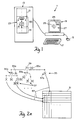
- Figure 1 illustrates a computer system 11 employing an embodiment of the present invention.
- a digital processor 13 coupled to a keyboard 17 and mouse 15 to receive user input therefrom, and coupled to a display unit 19 to display output thereon.
- a finite element modeling computer program 21 employing the present invention computer apparatus 23.
- the computer program 21 enables a user to model a desired object using finite element analysis.
- the computer program 21 generates a model of a subject object having a plurality of discrete elements defined in part by user input data and in part by processor calculations performed on the input data.
- the computer program 21 (through the digital processor 13) enables display of the generated model in a screen view on the display unit 19 and enables user interaction with the screen view of the model through keyboard 17 and/or mouse 15 operations.
- Methods and means for accomplishing the foregoing are known in the art and include computer programs such as "ANSYS” by Swanson Analysis Systems, Inc., "PATRAN” by PDA Engineering of Costa Mesa, CA, and graphics standard “PHIGS” (Programmers Hierarchical Interactive Graphics System) software systems available from Digital Equipment Corporation, Hewlett-Packard Company and the like for respective workstations.
- the present invention computer apparatus 23 subsequent to the generation of the model there are times when a user desires to know the data input (raw data used in calculations) or output (results of calculations) for each point in the model.
- the user interacts with the screen view of the model preferably through the mouse 15 as follows.
- the user selects a "query" item from a menu, or the like, displayed in the screen view, by positioning the screen cursor 29 in the screen view position of the desired menu selection and operating (clicking) a mouse button.
- the user then operates the mouse to move the screen cursor 29 to various positions in the screen view of the model, to effectively point to (or pick) various elements in the model.
- the present invention computer apparatus 23 performs the following actions.
- the present invention computer apparatus 23 causes the element to which the cursor 29 currently points to be displayed highlighted in the screen view.
- the present invention computer apparatus 23 outputs (i.e., displays) in the screen view the user requested information, according to the selected menu query item, regardless of how complex the model is.
- the user there is no need for the user to operate mouse buttons and wait; merely moving the cursor 29 elsewhere in the screen view of the model selects a new element to query which in turn generates display of the user requested information.
- the present invention computer apparatus 23 provides a split screen of (or separate window in) the screen view of the model. Specifically, the present invention provides in one part 27 of the screen view a localized, detailed view of an element or neighboring elements to which the cursor 29 currently points. In a second part 25 of the screen view, the model is displayed in full with an indication, such as broken line rectangle, of the portion of the model shown in the first part 27.
- the present invention provides immediate feedback to the user, is less error prone (i.e. provides more precise user selection of model elements to view), and encourages much more thorough verification and interpretation of a model.
- the limit is not processing time, but memory to hold the model.
- the present invention computer apparatus 23 employs a memory block 31 for holding raw and calculated data of each element of the model, and a tree data structure 33 in working memory for searching and accessing the memory block 31 in shorter amounts of time than that possible in the prior art.
- the tree data structure 33 is arranged with a root 39 at the tree entry level, various subsequent levels of subtrees formed of tree nodes 35 and inner leaf nodes 55, and a terminal level of leaf nodes 37.
- Each leaf node 37, 55 holds a pointer 57 to a respective location in the memory block 31 which holds the desired (raw and calculated) data of a respective element of the model.
- the pointers 57 are created as the tree 33 is built.
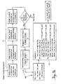
- the tree 33 is built in a preprocessing phase and used in the interactive phase as illustrated in Figs 3a-3b.
- the idea is that the geometric data of the model is static at the time a query operation is initiated. Hence, the time spent preprocessing the geometric data will be amortized over a large number of interactive queries. Querying is handled so quickly that output data can be updated continuously in response to cursor motion, even on low cost desktop workstations.
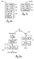
- Initialization 65 includes establishing a pointer to the root 39 of the tree data structure 33, allocating memory for the tree 33 and memory block 31, and recording identification (or association) of the tree 33 and memory block 31 with the particular model. Further, during initialization 65, the invention computer apparatus 23 enables the geometric finite elements and pertinent menus to be projected in the screen view. This is typically performed in response to user selection of a view of the model. In effect this serves to define a current session and the working (subject) elements of the model for the session.
- the invention computer apparatus 23 When a query operation is initiated by a menu pick, the invention computer apparatus 23 recursively constructs the tree 33, one tree node 35 and associated leaf nodes 37, 55 at a time, as indicated at 67 in Fig. 3a and described next with reference to the flow diagram of Fig. 3b and illustration of Figures 4a-4g.
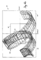
- a desired model is shown formed of generally prism shaped elements 83 connected in series.
- the present invention computer apparatus 23 calculates a two dimensional bounding box 81 (e.g., a rectangle as shown in Figure 4a) about the current set of elements 83 displayed in the model.
- the present invention computer apparatus 23 accomplishes this by linearly scanning the set of elements 83 and determining the greatest distance along two orthogonal axes (for example x and y axes in the first four steps 71 of Fig. 3b) that the elements 83 span.
- the present invention computer apparatus 23 determines if there are fewer than a preassigned number of elements (for example three or so) within the bounding box 81. If there are, then the elements are designated as a "spanning set" and represented by an inner leaf node 55 branching from the current working tree node 35 of the tree 33.
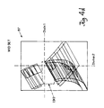
- two orthogonal dividing lines (Divlne 1 and Divlne 2 shown in Figure 4b) are calculated for the bounding box 81, typically at the mid points of the sides of the box's rectangular shape as detailed at 69 in Fig. 3b. It is understood that other points are suitable in other implementations of the tree 33.
- one dividing line lies along the major axis of the bounding box 81 and longitudinally divides the rectangle shape in half.
- the second dividing line lies along the minor axis of the bounding box 81 and further divides the rectangle shape in half along an orthogonal direction.
- the longest dividing line i.e. the dividing line along the major axis, is designated as the "splitting axis.” It is understood that in a like manner the shortest dividing line may serve as the splitting axis.
- the current set of elements 83 is then split into subsets according to the segments into which the bounding box 81 has been divided by the dividing lines. It is noted that the segments into which the bounding box 81 has been divided are rectangles or sub-bounding boxes themselves. Those elements 83 which straddle both dividing lines are placed in a "spanning set" and represented by an inner leaf node 55 branching from the current working tree node 35 of the tree 33. The remaining elements are placed in left, middle or right subtrees of the current working tree node 35 depending on whether the elements are completely to one side of the splitting axis, whether they straddle the splitting axis or whether they are on the opposite side of the splitting axis, respectively. These subtrees (i.e. subsets of elements) are recorded in respective nodes of the tree 33, in particular each subtree has a root node defined by a respective tree node 35 branching from the current working tree node 35.
- each subtree is recognized as containing a respective subset of model elements 83 according to the segments (i.e., sub-bounding boxes) into which the bounding box 81 was divided.
- segments i.e., sub-bounding boxes
- each subtree there is a corresponding sub-bounding box about the subset of model elements which define the subtree.
- Each sub-bounding box is handled as a bounding box in its own right and is recursively processed using the foregoing bounding box and dividing lines techniques i.e., by a call to the tree construction procedure 67 outlined in Fig. 3b.
- Divlne 2 ( Figure 4b) serves as the splitting axis.
- Formed to the left of and including the splitting axis (Divlne 2) is the subset 85 of model elements within its own bounding box as shown in Figures 4b and 4c.
- the subset 85 of elements 83 is placed in a left subtree of the current working tree and recorded in a set of tree nodes (root node only shown) branching from the current working tree node 35 as illustrated at L in Figure 4g.
- element subset 87 Bridging the splitting axis is element subset 87 shown in Figure 4b.
- the subset 87 of elements 83 is placed in a middle subtree and recorded in a set of tree nodes with a root node branching from the current working tree node 35 as illustrated at M in Figure 4g.
- the middle subset 87 is shown in its own bounding box (i.e., sub-bounding box of bounding box 81) as defined by the extent along x-y axes of the elements that bridge Divlne 2.
- Subset 87 excludes the elements 83 of spanning set 91 described below.
- subset 89 ( Figure 4a) in its own bounding box (i.e., sub-bounding box of bounding box 81) as independently shown in Figure 4e.
- the subset 89 of elements 83 is placed in a right subtree of the current working tree and recorded in a set of tree nodes with a root node branching from the current working tree node 35 illustrated at R in Figure 4g.
- the subset 91 of elements 83 which straddles both Divlnel and Divlne 2 in Figure 4b forms a spanning set.
- This set is represented by and recorded in inner leaf node 55 branching from the current working tree node 35 as illustrated in Figure 4g.
- Figure 4f shows this subset 91 in its own bounding box as defined by the extent along x-y axes of elements that straddle both Divlne1 and Divlne2. These are the elements excluded from middle subset 87 ( Figure 4d).
- leaf nodes 37, 55 correspond to spanning sets and are designated with an "S" in Fig. 2a and tree nodes 35 are indicated with a "T” in Fig. 2a.
- Each tree node 35 and leaf node 37, 55 of the tree 33 holds respective information in memory records illustrated in Figures 2b and 2c.
- the record for a tree node 35 as illustrated in Fig. 2b has a heading 41 which indicates that the record corresponds to a tree node 35 as opposed to a leaf node 37, 55.
- a coordinates field 43 of the record indicates x, y coordinates of the bounding box defined for the tree node 35 of the record.
- Field 45 indicates the splitting axis established for the bounding box.
- the following fields 47 provide four pointers into memory block 31.
- the first pointer points to the memory block 31 addresses of model elements of the spanning set, i.e. set of elements which straddle both dividing lines of the bounding box.
- a second pointer indicates the memory block 31 addresses of model elements of the left subtree which branches from the tree node 35 associated with this record.
- a third pointer points to memory block 31 addresses containing the model elements of a middle subtree that branches from the node 35 of the record.
- a fourth pointer points to memory block 31 addresses for the model elements of a right subtree that branches from the node 35 of the record.
- a record associated with a leaf node 37, 55 of the tree 33 and hence a spanning set has three fields as follows.
- a header field 49 provides an indication that the record holds information pertaining to a leaf node 37, 55 (spanning set).
- a second field 51 provides the geometric coordinates of the bounding box.
- a third field 53 provides a pointer to the list of model elements in the spanning set.
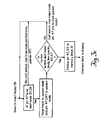
- the tree 33 is used repeatedly for interactive querying or hidden line drawing and other applications.
- a user selects a region of a desired model displayed in the screen view on the display unit 19 by positioning the cursor 29 on a displayed element in the sought region.
- the present invention displays the region near the screen cursor 29 in a main part 27 of the screen view and outputs to the screen some numerical data (such as a stress value or a 3D coordinate) about the element positioned closest to the cursor 29.
- the present invention computer apparatus 23 recursively tests the subject region (preferably defined by a predetermined size rectangle or other closed geometric shape surrounding the cursor 29) against the tree 33.
- apparatus 23 follows pointers 47 (Fig.
- traversing is preferably by a recursive routine 79 that calls itself for each tree node 35 pointed to by pointers 47 of a node and otherwise processes nodes as follows and outlined in Fig. 3c. It is understood that other common methods (recursive or not) for traversing the tree 33 using pointers and bounding box information at each node of the tree are suitable.
- apparatus 23 determines whether any subtrees (tree nodes 35) or spanning sets (leaf nodes 37, 55) of the node have bounding boxes, as indicated in corresponding record fields 43, 51 respectively, which overlap the subject query region. If the coordinates of a node's bounding box at 43, 51 of Figs. 2b and 2c lie substantially in the subject region, apparatus 23 follows the spanning set pointer 47, 53 corresponding to the node and obtains element data from memory block 31. Apparatus 23 tests element location indicated in that data against the current cursor position. Where the two locations match, apparatus 23 further outputs the element data to display unit 19 for display on screen view part 27.
- screen position of line segments of a desired model may be quickly checked for intersection with coordinate positions within the bounding boxes of nodes in the tree 33. Determination of such an intersection is accomplished by traversing the tree 33 and testing nodes 35, 37 as described above. That is, positional information of the elements pointed to by particular nodes of the tree 33 are tested against the cursor position in the subject screen view of the model, to determine if there exist overlapping points or line segments in the model. Again, a logarithmic time per line rather than a linear query time is achieved by the present invention.
Landscapes
- Engineering & Computer Science (AREA)
- Physics & Mathematics (AREA)
- Theoretical Computer Science (AREA)
- Computer Hardware Design (AREA)
- Evolutionary Computation (AREA)
- Geometry (AREA)
- General Engineering & Computer Science (AREA)
- General Physics & Mathematics (AREA)
- Information Retrieval, Db Structures And Fs Structures Therefor (AREA)
- User Interface Of Digital Computer (AREA)
- Processing Or Creating Images (AREA)
Claims (5)
- Computervorrichtung in einem Computersystem (11) für einen Anwenderdialog mit Modellen finiter Elemente, wobei die Vorrichtung (i) einen Speicher als Quelle von Modellen von Objekten, wobei jedes Modell aus mehreren Elementen (83) gebildet ist, (ii) einen Speicherbereich, der Daten hält, die jedes Element definieren, (iii) eine Anzeigeeinheit (19) zum Anzeigen von Bildschirmansichten eines Modells sowie (iv) einen digitalen Prozessor aufweist, der mit der Quelle von Modellen, dem Speicherbereich und der Anzeigeeinheit gekoppelt ist und den Anwenderdialog mit der Bildschirmansicht eines Modells ermöglicht, wobei die Computervorrichtung im Speicherbereich auf Daten von Elementen eines gewünschten Modells zugreift, mit:wobei die Vorrichtung dadurch gekennzeichnet ist, daß der geometrische Bereich (81), der von Elementen abgedeckt ist, die Knoten auf einer gemeinsamen Ebene entsprechen, rechteckig ist und eine longitudinale Hauptachse besitzt, derart, daß die Knoten auf der gemeinsamen Ebene so angeordnet sind, daß ein erster Knoten, der einer Untermenge von auf einer Seite der longitudinalen Hauptachse liegenden Elementen entspricht, an einem Ende der gemeinsamen Ebene angeordnet ist, ein zweiter Knoten, der einer Untermenge von auf der gegenüberliegenden Seite der longitudinalen Hauptachse liegenden Elementen entspricht, am gegenüberliegenden Ende der gemeinsamen Ebene angeordnet ist und ein dritter Knoten, der einer Untermenge von die longitudinale Hauptachse überbrückenden Elementen entspricht, zwischen dem ersten und dem zweiten Knoten auf der gemeinsamen Ebene angeordnet ist, und wobei(a) einem Arbeitsspeicher mit einem Datenbaum (33), der umfaßt:einen Wurzelknoten (39) undmehrere Baumknoten (35) und Blattknoten (37), die Untermengen von Elementen eines gewünschten Modells entsprechen,wobei der Wurzelknoten (39) und die mehreren Baumknoten (35) und Blattknoten (37) hierarchisch in der Weise angeordnet sind, daß sich der Wurzelknoten auf der höchsten Ebene befindet, die Baumknoten (35) sich auf Zwischenebenen befinden und die Blattknoten (37) sich auf einer untersten Ebene befinden, wobei jeder Blatt knoten einen Hinweis auf eine Stelle im ersten Speicherbereich von Daten entsprechender Elemente schafft,wobei auf jeder der Zwischenebenen Knoten auf einer gemeinsamen Ebene gemäß räumlicher Beziehung entsprechender Untermengen von Elementen des Modells in bezug auf wenigstens eine Achse eines geometrischen Bereichs, der von den Elementen der entsprechenden Untermengen in einer Bildschirmansicht des Modells abgedeckt wird, angeordnet sind; und(b) einer Prozessoreinrichtung, die durch den digitalen Prozessor ausführbar ist und die den Datenbaum als Antwort auf einen Anwenderdialog mit einem gewünschten Element eines auf der Anzeigeeinheit angezeigten Modells durchläuft, wobei die Prozessoreinrichtung den Baum entsprechend einem geometrischen Bereich durchläuft, in dem das gewünschte Element in einer Bildschirmansicht des Modells angeordnet ist, indem sie bestimmt, ob irgendwelche Baumknoten (35) oder Blattknoten (37) mit einer Abfrageregion überlappen, wobei die Prozessoreinrichtung einen Blattknoten (37) in dem dem gewünschten Element entsprechenden Baum lokalisiert und aus dem Blattknoten (37) einen Hinweis auf den Ort im ersten Speicherbereich von Daten des gewünschten Elements erhält, so daß der Zugriff auf die Daten durch die Prozessoreinrichtung ermöglicht wird,der rechteckige geometrische Bereich (81) ferner eine Nebenachse enthält, die transversal zur longitudinalen Hauptachse verläuft; undder Datenbaum ferner einen Blattknoten (55) besitzt, der einer Untermenge von Elementen entspricht, die sowohl die longitudinale Hauptachse als auch die transversale Nebenachse überbrücken.
- Computervorrichtung nach Anspruch 1, wobei die Prozessoreinrichtung eine rekursive Routine zum Durchlaufen des Baums aufweist.
- Computervorrichtung nach Anspruch 1, wobei der Datenbaum in einem Arbeitsspeicher als Antwort auf den anfänglichen Anwenderbefehl zum Abfragen des gewünschten Modells rekursiv konstruiert wird.
- Verfahren für einen Anwenderdialog mit Modellen finiter Elemente in einem Computersystem, das (i) einen Speicher als Quelle von Modellen von Objekten, wobei jedes Modell aus mehreren Elementen gebildet ist, (ii) einen ersten Speicherbereich, der Daten hält, die jedes Element definieren, (iii) eine Anzeigeeinheit (19) zum Anzeigen von Bildschirmansichten eines Modells und (iv) einen digitalen Prozessor, der den Anwenderdialog mit der Bildschirmansicht des Modells ermöglicht, aufweist, wobei das Verfahren im Speicher auf Daten von Elementen eines gewünschten Elements zugreift und die folgenden Schritte enthält:wobei das Verfahren dadurch gekennzeichnet ist, daß der Schritt des Vorsehens eines Datenbaums ferner enthält:Vorsehen eines Datenbaums (33) mit einem Wurzelknoten (39) und mehreren Baumknoten (35) und Blattknoten (37) in einem Arbeitsspeicher, wobei die Blattknoten Elementen eines gewünschten Modells entsprechen und die Baumknoten Mengen der Elemente entsprechen, wobei der Wurzelknoten (39) und die mehreren Baumknoten (35) und Blattknoten (37) hierarchisch in der Weise angeordnet sind, daß sich der Wurzelknoten auf einer höchsten Ebene befindet, die Baumknoten sich auf Zwischenebenen befinden und die Blattknoten sich auf einer untersten Ebene befinden, wobei jeder Blattknoten einen Hinweis auf eine Stelle im ersten Speicherbereich von Daten entsprechender Elemente auf jeder der Zwischenebenen schafft, wobei Knoten auf einer gemeinsamen Ebene gemäß einer räumlichen Beziehung entsprechender Mengen von Elementen des Modells in bezug auf wenigstens eine Achse eines geometrischen Bereichs (81), der von den Elementen in einer Bildschirmansicht des Modells abgedeckt wird, angeordnet sind;Durchlaufen des Baums entsprechend dem geometrischen Bereich, in dem das gewünschte Element in der angezeigten Bildschirmansicht des Modells angeordnet ist, als Antwort auf einen Anwenderdialog mit einem gewünschten Element eines in der Bildschirmansicht der Anzeigeeinheit angezeigten Modells, indem bestimmt wird, ob irgendwelche Baumknoten (35) oder Blattknoten (37) mit einer Abfrageregion überlappen,wobei der Schritt des Durchlaufens das Lokalisieren eines Blattknotens in dem dem gewünschten Element entsprechenden Datenbaum umfaßt; undErhalten eines Hinweises auf die Stelle im ersten Speicherbereich von Daten des gewünschten Elements aus dem lokalisierten Blattknoten, derart, daß der Zugriff auf die Daten des gewünschten Elements in dem Speicherbereich ermöglicht wird,Definieren einer rechteckigen Grenze (81) des geometrischen Bereichs, der von den Elementen, die Knoten auf einer gemeinsamen Ebene entsprechen, abgedeckt wird, derart, daß eine longitudinale Hauptachse und eine transversale Nebenachse des geometrischen Bereichs vorhanden sind; undAnordnen von Baumknoten auf einer gemeinsamen Ebene durch(i) Anordnen eines ersten Baumknotens, der einer Menge von auf einer Seite der longitudinalen Hauptachse liegenden Elementen entspricht, an einem Ende der gemeinsamen Ebene,(ii) Anordnen eines zweiten Baumknotens, der Mengen von auf der gegenüberliegenden Seite der longitudinalen Hauptachse liegenden Elementen entspricht, an einem gegenüberliegenden Ende der gemeinsamen Ebene; und(iii) Anordnen eines dritten Knotens, der Elementen entspricht, die die longitudinale Hauptachse überbrücken, zwischen dem ersten und dem zweiten Baumknoten, undwobei der Schritt des Vorsehens eines Datenbaums ferner das Definieren von Blattknoten umfaßt, die Elementen des Modells entsprechen, die sowohl die longitudinale Hauptachse als auch die transversale Nebenachse überbrükken.
- Verfahren nach Anspruch 4, bei dem der Schritt des Vorsehens eines Datenbaums das rekursive Konstruieren des Baums in dem Arbeitsspeicherbereich als Antwort auf einen anfänglichen Anwenderbefehl zum Abfragen des gewünschten Modells umfaßt und
bei dem der Schritt des Durchlaufens des Datenbaums und des Lokalisierens eines dem gewünschten Element entsprechenden Blattknotens ferner das rekursive Suchen des Blattknotens umfaßt.
Applications Claiming Priority (3)
| Application Number | Priority Date | Filing Date | Title |
|---|---|---|---|
| US678691 | 1991-04-01 | ||
| US07/678,691 US5289567A (en) | 1991-04-01 | 1991-04-01 | Computer apparatus and method for finite element identification in interactive modeling |
| PCT/US1992/002520 WO1992017854A1 (en) | 1991-04-01 | 1992-03-31 | Computer apparatus and method for finite element identification in interactive modeling |
Publications (2)
| Publication Number | Publication Date |
|---|---|
| EP0532740A1 EP0532740A1 (de) | 1993-03-24 |
| EP0532740B1 true EP0532740B1 (de) | 1999-11-24 |
Family
ID=24723868
Family Applications (1)
| Application Number | Title | Priority Date | Filing Date |
|---|---|---|---|
| EP92910131A Expired - Lifetime EP0532740B1 (de) | 1991-04-01 | 1992-03-31 | Computervorrichtung und verfahren zur identifizierung von finite-elementen in der interaktiven modellierung |
Country Status (4)
| Country | Link |
|---|---|
| US (1) | US5289567A (de) |
| EP (1) | EP0532740B1 (de) |
| DE (1) | DE69230331T2 (de) |
| WO (1) | WO1992017854A1 (de) |
Families Citing this family (39)
| Publication number | Priority date | Publication date | Assignee | Title |
|---|---|---|---|---|
| US5710899A (en) * | 1991-12-06 | 1998-01-20 | Lucent Technologies Inc. | Interactive selectors for selecting subsets of a set of values |
| US6003033A (en) * | 1992-02-28 | 1999-12-14 | International Business Machines Corporation | System and method for describing and creating a user defined arbitrary data structure corresponding to a tree in a computer memory |
| US5479598A (en) * | 1992-10-23 | 1995-12-26 | International Business Machines Corporation | Compact graphical parallel program user output interface controlled directly by the parallel computer program |
| US5574835A (en) * | 1993-04-06 | 1996-11-12 | Silicon Engines, Inc. | Bounding box and projections detection of hidden polygons in three-dimensional spatial databases |
| US5848404A (en) * | 1997-03-24 | 1998-12-08 | International Business Machines Corporation | Fast query search in large dimension database |
| US5940822A (en) * | 1997-08-29 | 1999-08-17 | International Business Machines Corporation | Encoding method of members related by multiple concept or group hierarchies and identification of members in a corpus or a database that are descendants of one or more selected concepts or groups from the encoding |
| US5987237A (en) * | 1997-09-02 | 1999-11-16 | Hewlett-Packard Company | Framework for rules checking |
| US6476807B1 (en) | 1998-08-20 | 2002-11-05 | Apple Computer, Inc. | Method and apparatus for performing conservative hidden surface removal in a graphics processor with deferred shading |
| US6771264B1 (en) * | 1998-08-20 | 2004-08-03 | Apple Computer, Inc. | Method and apparatus for performing tangent space lighting and bump mapping in a deferred shading graphics processor |
| US6212486B1 (en) * | 1998-09-17 | 2001-04-03 | Ford Global Technologies, Inc. | Method of identifying critical elements in fatigue analysis with von mises stress bounding and filtering modal displacement history using dynamic windowing |
| US6272387B1 (en) * | 1998-11-06 | 2001-08-07 | The Boeing Company | Wire harness system |
| DE69901959T2 (de) * | 1999-09-03 | 2003-02-27 | Autodesk, Inc. | Anwenderdefinierbare Parameter zur Finite-Element-Analyseberechnung in einem Cad-Programm |
| US6633837B1 (en) * | 1999-10-14 | 2003-10-14 | Object Reservoir | Method and system for generating software code using a symbolic language translator |
| US6463500B1 (en) | 2000-01-04 | 2002-10-08 | International Business Machines Corporation | Apparatus and method to access computer memory by processing object data as sub-object and shape parameter |
| US6523152B1 (en) | 2000-03-08 | 2003-02-18 | Hewlett-Packard Company | Framework for rules checking utilizing resistor, nonresistor, node and small node data structures |
| US9208270B2 (en) | 2000-08-02 | 2015-12-08 | Comsol Ab | System and method for establishing bidirectional links between multiphysics modeling and design systems |
| AU767760B2 (en) * | 2000-08-14 | 2003-11-20 | Canon Kabushiki Kaisha | Outline orientation based on nested edge containment |
| KR100439087B1 (ko) * | 2002-05-09 | 2004-07-05 | 한국과학기술원 | 3차원 물체 상세화 모델링 방법 |
| US20040267811A1 (en) * | 2003-06-27 | 2004-12-30 | International Business Machines Corporation | Host initiated display, host initiated display application program interface, and host initiated display method |
| US8458164B2 (en) * | 2003-07-15 | 2013-06-04 | International Business Machines Corporation | Query model tool and method for visually grouping and ungrouping predicates |
| US20050015368A1 (en) * | 2003-07-15 | 2005-01-20 | International Business Machines Corporation | Query modelling tool having a dynamically adaptive interface |
| US20050015361A1 (en) * | 2003-07-15 | 2005-01-20 | International Business Machines Corporation | Model content provider with reusable components for supporting a plurality of GUI API's |
| US20050015363A1 (en) * | 2003-07-15 | 2005-01-20 | International Business Machines Corporation | Method and structure for representing complex query elements in a modelling tool |
| US7599044B2 (en) | 2005-06-23 | 2009-10-06 | Apple Inc. | Method and apparatus for remotely detecting presence |
| US7242169B2 (en) * | 2005-03-01 | 2007-07-10 | Apple Inc. | Method and apparatus for voltage compensation for parasitic impedance |
| US7577930B2 (en) | 2005-06-23 | 2009-08-18 | Apple Inc. | Method and apparatus for analyzing integrated circuit operations |
| US9298311B2 (en) * | 2005-06-23 | 2016-03-29 | Apple Inc. | Trackpad sensitivity compensation |
| US7913190B2 (en) * | 2005-07-18 | 2011-03-22 | Dassault Systèmes | Method, system and software for visualizing 3D models |
| US9323503B1 (en) * | 2009-12-29 | 2016-04-26 | Comsol Ab | System and method for accessing settings in a multiphysics modeling system using a model tree |
| US7433191B2 (en) * | 2005-09-30 | 2008-10-07 | Apple Inc. | Thermal contact arrangement |
| US7598711B2 (en) * | 2005-11-23 | 2009-10-06 | Apple Inc. | Power source switchover apparatus and method |
| US7873237B2 (en) * | 2006-02-17 | 2011-01-18 | Dassault Systèmes | Degrading 3D information |
| US20080088621A1 (en) * | 2006-10-11 | 2008-04-17 | Jean-Jacques Grimaud | Follower method for three dimensional images |
| US11610037B2 (en) | 2009-12-29 | 2023-03-21 | Comsol Ab | System and method for accessing settings in a multiphysics modeling system using a model tree |
| US8626475B1 (en) | 2009-12-29 | 2014-01-07 | Comsol Ab | System and method for accessing a multiphysics modeling system via a design system user interface |
| US9697326B1 (en) * | 2012-02-27 | 2017-07-04 | Kelly Eric Bowman | Topology graph optimization |
| DE102015009783A1 (de) | 2015-07-27 | 2017-02-02 | Kurt Becker | Modulare Vorrichtung zur Erzeugung und Messung mehrdimensionaler, räumlich und zeitlich definierter schwacher Elektro-Magnetischer-Felder (sEMF) |
| CN111228793B (zh) * | 2020-01-21 | 2021-11-19 | 腾讯科技(深圳)有限公司 | 交互界面的显示方法和装置、存储介质及电子装置 |
| JP2021149748A (ja) * | 2020-03-23 | 2021-09-27 | キオクシア株式会社 | 応力解析方法及び半導体装置の製造方法 |
Family Cites Families (1)
| Publication number | Priority date | Publication date | Assignee | Title |
|---|---|---|---|---|
| US5159664A (en) * | 1988-07-06 | 1992-10-27 | Hitachi Ltd. | Graphic display apparatus |
-
1991
- 1991-04-01 US US07/678,691 patent/US5289567A/en not_active Expired - Lifetime
-
1992
- 1992-03-31 WO PCT/US1992/002520 patent/WO1992017854A1/en not_active Ceased
- 1992-03-31 DE DE69230331T patent/DE69230331T2/de not_active Expired - Fee Related
- 1992-03-31 EP EP92910131A patent/EP0532740B1/de not_active Expired - Lifetime
Also Published As
| Publication number | Publication date |
|---|---|
| US5289567A (en) | 1994-02-22 |
| EP0532740A1 (de) | 1993-03-24 |
| DE69230331T2 (de) | 2000-08-24 |
| DE69230331D1 (de) | 1999-12-30 |
| WO1992017854A1 (en) | 1992-10-15 |
Similar Documents
| Publication | Publication Date | Title |
|---|---|---|
| EP0532740B1 (de) | Computervorrichtung und verfahren zur identifizierung von finite-elementen in der interaktiven modellierung | |
| US5021976A (en) | Method and system for generating dynamic, interactive visual representations of information structures within a computer | |
| EP0981098B1 (de) | Verfahren und Gerät um Ansichten von hierarchisch zusammengefassten Daten herzustellen und anzuzeigen | |
| US7529727B2 (en) | Using an index to access a subject multi-dimensional database | |
| North et al. | Applications of graph visualization | |
| US6373484B1 (en) | Method and system for presenting data structures graphically | |
| US4742473A (en) | Finite element modeling system | |
| US5530942A (en) | Graphic and text interactive user interface for a program execution analyzer | |
| US5438526A (en) | Program generation method for particles simulation | |
| EP0982670A2 (de) | Dynamische Objektvisualisierung und Kodegeneration | |
| US6201884B1 (en) | Apparatus and method for trend analysis in graphical information involving spatial data | |
| US8484605B2 (en) | Analysis of physical systems via model libraries thereof | |
| US5748197A (en) | Dynamic computation of a line segment arrangement using finite precision arithmetic for use in a processor controlled system | |
| EP0640906B1 (de) | Anzeigegerät | |
| US7605814B1 (en) | Method and tool for viewing data | |
| JPH0612552B2 (ja) | 電子化文書検索装置 | |
| GB2309142A (en) | Drawing three-dimensional objects in computer-aided design systems | |
| Sammon Jr et al. | An interactive-graphic subsystem for pattern analysis | |
| JPH10222506A (ja) | 文書作成支援装置 | |
| Shah et al. | amdb: A visual access method development tool | |
| EP0443531B1 (de) | Verwaltungsverfahren und -system für graphische Daten | |
| Weller et al. | Software architecture for graphical interaction | |
| JPH01189722A (ja) | 電子化文書検索装置 | |
| JPH0612554B2 (ja) | 電子化文書検索装置 | |
| Jones | Conflict resolution in cartographic name placement |
Legal Events
| Date | Code | Title | Description |
|---|---|---|---|
| PUAI | Public reference made under article 153(3) epc to a published international application that has entered the european phase |
Free format text: ORIGINAL CODE: 0009012 |
|
| 17P | Request for examination filed |
Effective date: 19930104 |
|
| AK | Designated contracting states |
Kind code of ref document: A1 Designated state(s): DE FR GB |
|
| 17Q | First examination report despatched |
Effective date: 19980116 |
|
| GRAG | Despatch of communication of intention to grant |
Free format text: ORIGINAL CODE: EPIDOS AGRA |
|
| GRAG | Despatch of communication of intention to grant |
Free format text: ORIGINAL CODE: EPIDOS AGRA |
|
| GRAH | Despatch of communication of intention to grant a patent |
Free format text: ORIGINAL CODE: EPIDOS IGRA |
|
| GRAH | Despatch of communication of intention to grant a patent |
Free format text: ORIGINAL CODE: EPIDOS IGRA |
|
| GRAA | (expected) grant |
Free format text: ORIGINAL CODE: 0009210 |
|
| AK | Designated contracting states |
Kind code of ref document: B1 Designated state(s): DE FR GB |
|
| REF | Corresponds to: |
Ref document number: 69230331 Country of ref document: DE Date of ref document: 19991230 |
|
| ET | Fr: translation filed | ||
| REG | Reference to a national code |
Ref country code: GB Ref legal event code: 732E |
|
| PLBE | No opposition filed within time limit |
Free format text: ORIGINAL CODE: 0009261 |
|
| 26N | No opposition filed | ||
| PG25 | Lapsed in a contracting state [announced via postgrant information from national office to epo] |
Ref country code: DE Free format text: LAPSE BECAUSE OF NON-PAYMENT OF DUE FEES Effective date: 20010103 |
|
| PG25 | Lapsed in a contracting state [announced via postgrant information from national office to epo] |
Ref country code: FR Free format text: LAPSE BECAUSE OF NON-PAYMENT OF DUE FEES Effective date: 20010531 |
|
| REG | Reference to a national code |
Ref country code: FR Ref legal event code: ST |
|
| REG | Reference to a national code |
Ref country code: FR Ref legal event code: RN Ref country code: FR Ref legal event code: D3 |
|
| REG | Reference to a national code |
Ref country code: GB Ref legal event code: IF02 |
|
| PGFP | Annual fee paid to national office [announced via postgrant information from national office to epo] |
Ref country code: GB Payment date: 20020327 Year of fee payment: 11 |
|
| PG25 | Lapsed in a contracting state [announced via postgrant information from national office to epo] |
Ref country code: GB Free format text: LAPSE BECAUSE OF NON-PAYMENT OF DUE FEES Effective date: 20030331 |
|
| GBPC | Gb: european patent ceased through non-payment of renewal fee |
Effective date: 20030331 |
|
| PGFP | Annual fee paid to national office [announced via postgrant information from national office to epo] |
Ref country code: FR Payment date: 20060317 Year of fee payment: 15 |