EP0639880B2 - Verfahren zur Stabilisierung eines Stromnetzes gegen Blindlastschwankungen und Blindleistungskompensationseinrichtung - Google Patents
Verfahren zur Stabilisierung eines Stromnetzes gegen Blindlastschwankungen und Blindleistungskompensationseinrichtung Download PDFInfo
- Publication number
- EP0639880B2 EP0639880B2 EP94111523A EP94111523A EP0639880B2 EP 0639880 B2 EP0639880 B2 EP 0639880B2 EP 94111523 A EP94111523 A EP 94111523A EP 94111523 A EP94111523 A EP 94111523A EP 0639880 B2 EP0639880 B2 EP 0639880B2
- Authority
- EP
- European Patent Office
- Prior art keywords
- reactive
- power
- signal
- current
- function
- Prior art date
- Legal status (The legal status is an assumption and is not a legal conclusion. Google has not performed a legal analysis and makes no representation as to the accuracy of the status listed.)
- Expired - Lifetime
Links
Images

Classifications
-
- H—ELECTRICITY
- H02—GENERATION; CONVERSION OR DISTRIBUTION OF ELECTRIC POWER
- H02J—CIRCUIT ARRANGEMENTS OR SYSTEMS FOR SUPPLYING OR DISTRIBUTING ELECTRIC POWER; SYSTEMS FOR STORING ELECTRIC ENERGY
- H02J3/00—Circuit arrangements for AC mains or AC distribution networks
- H02J3/18—Arrangements for adjusting, eliminating or compensating reactive power in networks
- H02J3/1892—Arrangements for adjusting, eliminating or compensating reactive power in networks the arrangements being an integral part of the load, e.g. a motor, or of its control circuit
Definitions
- the invention is based on one Method for stabilizing a power supply device or a power grid against fluctuations in reactive load at least one electrical device or variable reactive load system according to the generic term of claim 1 and of a reactive power compensation device according to the generic term of claim 6.
- the invention as set out in claims 1 and 4 is defined, solves the problem, a method and a reactive power compensation device for stabilization a power supply device or one Power grid against fluctuations in reactive load at least an electrical device or system more variable To further develop the reactive load of the type mentioned at the beginning that reactive load fluctuations better be compensated.
- An advantage of the invention is that a detection of the total current for compensation the reactive power fluctuations the reactive powers all loads with the system to be compensated related, compensated relatively quickly become.
- the result is a constant inductive reactive power for the entire system with built-in or switched capacitor banks or with harmonic Filters can be compensated.
- This Regulation of the reactive load fluctuations can be Systems with variable reactive loads, even on very weak ones Connect power grids.
- Plants with over 50 MW can thus be started Connect power networks, their short-circuit power is at least equal to 10 times the system output.
- FIG. 1 shows an arc furnace (8) with a Electrode or cathode (7), which has 2 reactors or choke coils (6, 6 '), each in parallel branches a rectifier (5, 5 '), one furnace transformer each (2, 2 ') with several switching stages and one current transformer each (3, 3 ') are connected in series to an AC network (1) with an alternating voltage of 22 kV connected.
- One in the bottom of the arc furnace (8) arranged second electrode or anode (12) is connected to the positive pole of the rectifier (5) (not shown).
- Arc (10) Between the bottom of the cathode (7) and a not shown to be melted Good or scrap as well as with the surface of one Melt or a molten bath (11) burns in Arc (10).
- the current transformers (3, 3 ') in the AC feed lines to the rectifiers (5, 5') are used to detect partial current actual signals (i ist1 , i ist2 ) and to use non-negating inputs of a summer (23) and 2 negating inputs of a comparator or summer (13 ) fed. A non-negating input of this summer (13) z. B. from an unillustrated potentiometer a specifiable desired current value signal (i soll) is supplied.
- the summer (13) On the output side, the summer (13) is connected to a current regulator (14) with proportional-integral characteristics, which on the output side supplies a rectifier control signal ( ⁇ ist ), corresponding to an ignition angle, an ignition pulse converter (15), which outputs the rectifiers (5, 5 ') controls.
- the rectifier manipulated variable signal ( ⁇ ist ) is connected via an attenuator (16 ') or a bandpass filter (16) for signal adaptation, limit value monitoring and screening of undesired frequencies to a negating input of a summer (17), the non-negating input of which is a predeterminable electrode controller reference variable signal ( ⁇ should ), corresponding to an ignition angle setpoint in the range from 15 ° to 50 °, preferably in the range from 25 ° to 35 °.
- the summer (17) is connected to an electrode regulator (18) with a proportional characteristic, which acts on the output side via a valve amplifier (19) on a valve (20) of an electrode adjustment device (21).
- the electrode adjustment device (21) e.g. B. a hydraulic pump with an adjustment mechanism and an electrode speed controller is mechanically coupled to the cathode (7) and enables its height adjustment; it acts as a 1st order delay element.
- the electrode control works about 10 times slower than the current control.
- the height adjustment of the cathode (7) is carried out so that the rectifier (5) on average with a modulation of z. B. 25 ° el. operates independently of the secondary voltage of the furnace transformer (2) and (to i) the set current target value.
- values and signals assigned to them are identified identically.
- the frequencies to be screened by the bandpass filter (16) include frequencies in the range of 0.5 Hz - 20 Hz
- the current set value (i soll) specified accordingly. If the current is reduced but the level of the rectifier (5) is still the same, you will probably get smaller outputs. As a result of lower voltage losses in the AC network (1), the arc (10) becomes longer. However, the furnace process also requires shorter arcs (10) for smaller outputs. To achieve this, it is possible with a change of the current setpoint (I soll) also specify a corresponding new desired value for the level of the rectifier (5) simultaneously.
- a 3-phase reactive power compensator (31) provided for each AC phase an AC power controller (28) in series with one Choke coil (29) and a switch (30), the is connected to the AC network (1).
- the 3 AC power controllers (28) are in a delta connection with one another connected and are each from an ignition pulse converter (27) controlled.
- the AC network (1) can be tapped via a current transformer (33), from which a total current (i 33 ) of the entire system with auxiliary operations and filter branches (4, 4 '), not shown, for capacitive reactive power can also be tapped via a high-voltage transformer and 2 switches a 3-phase high-voltage network (32) with an AC voltage of 220 kV is connected.
- a current transformer 33
- i 33 total current intensity
- a voltage detector AC voltage (U 1) of the AC network (1) and a predeterminable nominal phase angle of the input of a phase angle regulator (35) are supplied to the output side, a desired reactive power signal (Q des8 ) for the arc furnace (8) to a negating input of a summer (25).
- a filter reactive power signal (Q F ) corresponding to the constant capacitive reactive power of the filter branches (4, 4 ') is fed to a non-negating input of the summer (25).
- Q 8th k1 * i is ⁇ [1 - (cos ⁇ is - k2 ⁇ i is ) 2 ] 0.5 , where k1 and k2 are plant-specific factors with 0.1 ⁇ k1 ⁇ 1, preferably with 0.3 ⁇ k1 ⁇ 0.6 and 0.7 ⁇ 10 -3 ⁇ k2 ⁇ 1.3 ⁇ 10 -3 , preferably with 0, 9 ⁇ 10 -3 ⁇ k2 ⁇ 1.1 ⁇ 10 -3 .
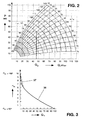
- the rectifier manipulated variable signal ( ⁇ ist ) is given in degrees, the actual current signal (i ist ) in kA, the real power (P) in MW on the ordinate and the reactive power (Q) in MVar on the abscissa.
- ⁇ ist the rectifier manipulated variable signal
- Q reactive power
- FIG 3 shows a characteristic curve (36) of the function implemented by means of the function generator (26): Q G ⁇ ⁇ St ° / 90 ° - 2 - (sin 2 ⁇ St ) / ⁇ , where ( ⁇ St ) in degrees on the ordinate and (Q G ) in% on the abscissa.
- the ideal curve (36) can be approximated by segments (37) indicated by dashed lines and used to determine the value of the stabilization ignition angle ( ⁇ St ).
- the example shown relates to a system with an active power (P) of 60 MW with a direct current of 100 kA and an installed reactive or compensation power of 30 MVar.
Landscapes
- Engineering & Computer Science (AREA)
- Power Engineering (AREA)
- Control Of Electrical Variables (AREA)
- Supply And Distribution Of Alternating Current (AREA)
- Emergency Protection Circuit Devices (AREA)
- Chemical Or Physical Treatment Of Fibers (AREA)
Applications Claiming Priority (2)
| Application Number | Priority Date | Filing Date | Title |
|---|---|---|---|
| DE4327894A DE4327894A1 (de) | 1993-08-19 | 1993-08-19 | Verfahren zur Stabilisierung eines Stromnetzes gegen Blindlastschwankungen und Blindleistungskompensationseinrichtung |
| DE4327894 | 1993-08-19 |
Publications (4)
| Publication Number | Publication Date |
|---|---|
| EP0639880A2 EP0639880A2 (de) | 1995-02-22 |
| EP0639880A3 EP0639880A3 (de) | 1995-12-13 |
| EP0639880B1 EP0639880B1 (de) | 1997-10-22 |
| EP0639880B2 true EP0639880B2 (de) | 2001-01-24 |
Family
ID=6495546
Family Applications (1)
| Application Number | Title | Priority Date | Filing Date |
|---|---|---|---|
| EP94111523A Expired - Lifetime EP0639880B2 (de) | 1993-08-19 | 1994-07-23 | Verfahren zur Stabilisierung eines Stromnetzes gegen Blindlastschwankungen und Blindleistungskompensationseinrichtung |
Country Status (9)
| Country | Link |
|---|---|
| US (1) | US5627454A (pt) |
| EP (1) | EP0639880B2 (pt) |
| JP (1) | JPH07170664A (pt) |
| CN (1) | CN1041779C (pt) |
| AT (1) | ATE159626T1 (pt) |
| BR (1) | BR9403274A (pt) |
| DE (2) | DE4327894A1 (pt) |
| ES (1) | ES2111216T5 (pt) |
| RU (1) | RU2126580C1 (pt) |
Families Citing this family (22)
| Publication number | Priority date | Publication date | Assignee | Title |
|---|---|---|---|---|
| DE4436353C2 (de) * | 1994-10-12 | 1997-02-06 | Abb Management Ag | Verfahren zur Stabilisierung eines Wechselstromnetzes gegen Blindlastschwankungen und Blindleistungskompensationseinrichtung |
| DE19617191C2 (de) * | 1996-04-29 | 1998-07-16 | Siemens Ag | Einrichtung zur Gleichstromversorgung für einen Gleichstromlichtbogenofen |
| DE19623540C1 (de) * | 1996-06-13 | 1997-12-18 | Asea Brown Boveri | Verfahren zur Stabilisierung eines Wechselstromnetzes gegen Blindleistungsschwankungen und Blindleistungskompensationseinrichtung |
| SE510197C2 (sv) * | 1997-02-06 | 1999-04-26 | Asea Brown Boveri | Förfarande och anordning för styrning av ett kondensatordon för en shuntkopplad statisk kompensatorenhet med deblockeringssignaler för indikering av icke strömförande tillstånd hos ingående ventiler |
| DE19920049C2 (de) * | 1999-04-23 | 2001-10-11 | Sms Demag Ag | Verfahren und Vorrichtung zur Stromversorgung eines über einen Lichtbogen betriebenen Schmelzaggregates |
| US6411643B1 (en) | 1999-09-30 | 2002-06-25 | Sms Demag, Inc | Automatic electrode regulator based on direct power factor regulation and method |
| US6226313B1 (en) * | 1999-10-18 | 2001-05-01 | Manoharan Thamodharan | Power source circuit and its control for three-phase electric arc furnace to reduce flicker |
| DE102005051232A1 (de) * | 2005-10-26 | 2007-05-03 | Sms Demag Ag | Steuervorrichtung für Wechselstrom-Reduktionsöfen |
| RU2390902C1 (ru) * | 2008-12-29 | 2010-05-27 | Игорь Владимирович Устименко | Способ повышения качества электрической энергии многофазной системы при симметрировании токов по одной из фаз |
| RU2382470C1 (ru) * | 2008-12-29 | 2010-02-20 | Игорь Владимирович Устименко | Способ повышения качества электрической энергии многофазной системы при симметрировании токов по заданной фазе и комбинированном отборе мощности |
| RU2382467C1 (ru) * | 2008-12-29 | 2010-02-20 | Игорь Владимирович Устименко | Способ повышения качества электрической энергии многофазной системы при симметрировании токов по заданной фазе |
| RU2382471C1 (ru) * | 2008-12-29 | 2010-02-20 | Игорь Владимирович Устименко | Способ повышения качества электрической энергии многофазной системы при симметрировании токов по одной из фаз и комбинированном отборе мощности |
| AU2009341480B2 (en) * | 2009-03-06 | 2015-09-17 | Abb Technology Ag | Poly-phase reactive power compensator |
| US20120314728A1 (en) * | 2011-06-08 | 2012-12-13 | Warner Power Llc | System and method to deliver and control power to an arc furnace |
| DE102013224736B4 (de) | 2012-12-21 | 2025-02-13 | Schäfer Elektronik Gmbh | Vorrichtung zur Korrektur von Wechselströmen |
| CN203734316U (zh) * | 2014-01-23 | 2014-07-23 | 安徽华正电气有限公司 | 一种双向无功调节电压的装置 |
| DE102014206008A1 (de) * | 2014-03-31 | 2015-10-01 | Siemens Aktiengesellschaft | Vorrichtung und Verfahren zur dynamischen Einstellung eines Elektrolichtbogenofens |
| IT201800004846A1 (it) * | 2018-04-24 | 2019-10-24 | Metodo di alimentazione elettrica di un forno elettrico ad arco e relativo apparato | |
| RU2741061C1 (ru) * | 2020-06-11 | 2021-01-22 | Федеральное государственное бюджетное образовательное учреждение высшего образования «Магнитогорский государственный технический университет им. Г. И. Носова» (ФГБОУ ВО «МГТУ им. Г.И. Носова») | Система управления многоуровневым активным фильтром |
| CN114740296B (zh) * | 2021-08-18 | 2024-08-09 | 广州晓云智慧科技有限公司 | 一种功率因数补偿设备工作状况监测方法 |
| CN115441477B (zh) * | 2022-09-29 | 2025-09-02 | 武汉大学 | 一种储能参与的高比例风电系统失步振荡抑制方法 |
| LV15892A (lv) * | 2023-04-11 | 2024-10-20 | Kopils Leonids | Līdzstrāvas elektriskā loka materiālu kausēšanas krāsns sistēma un paņēmiens |
Citations (1)
| Publication number | Priority date | Publication date | Assignee | Title |
|---|---|---|---|---|
| US5155740A (en) † | 1990-10-22 | 1992-10-13 | Nkk Corporation | Flicker compensating apparatus for DC arc furnace |
Family Cites Families (14)
| Publication number | Priority date | Publication date | Assignee | Title |
|---|---|---|---|---|
| CA713213A (en) * | 1960-09-09 | 1965-07-06 | The General Electric Company Limited | Voltage regulating apparatus |
| AT289258B (de) * | 1967-08-11 | 1971-04-13 | Wiener Schwachstromwerke Gmbh | Hilfseinrichtung für symmetrische oder unsymmetrische Wirk- und bzw. oder Blindleistungsverbraucher |
| FR2266347B1 (pt) * | 1974-03-27 | 1982-07-02 | Siemens Ag | |
| SU558349A1 (ru) * | 1975-08-07 | 1977-05-15 | Московский Ордена Ленина Энергетический Институт | Регулируема конденсаторна батаре и способ управлени ею |
| SU754567A1 (ru) * | 1978-03-13 | 1980-08-07 | Vasilij E Klimenko | Регулятор коэффициента мощности 1 |
| DE3002373A1 (de) * | 1980-01-23 | 1981-07-30 | Siemens AG, 1000 Berlin und 8000 München | Verfahren zur minderung der netzrueckwirkungen eines netzgefuehrten direktumrichters und steuerschaltung hierzu |
| DE3708468A1 (de) * | 1986-03-17 | 1987-09-24 | Siemens Ag | Verfahren und vorrichtung zum kompensieren von oberschwingungsbelastungen und/oder blindlast in einem versorgungsnetz |
| US4752736A (en) * | 1986-07-22 | 1988-06-21 | The Regents Of The University Of California | Center fed QD MRI RF coil |
| JPS6366617A (ja) * | 1986-09-09 | 1988-03-25 | Toshiba Corp | 無効電力補償装置 |
| SU1718328A1 (ru) * | 1988-06-17 | 1992-03-07 | Тольяттинский политехнический институт | Трехфазное комбинированное фильтрокомпенсирующее устройство |
| DE3915213A1 (de) * | 1989-05-05 | 1990-11-08 | Licentia Gmbh | Anordnung zur modifizierung der strangblindleistungs-sollwerte einer m-phasigen blindleistungs-kompensationsanlage mit eingeschraenktem leistungsstellvermoegen |
| DE69022854T2 (de) * | 1990-10-31 | 1996-05-02 | Nippon Kokan Kk | Einrichtung zur Flimmerkompensation für einen Gleichstromlichtbogenofen. |
| AU647576B2 (en) * | 1991-02-08 | 1994-03-24 | Asea Brown Boveri Limited | Process for electrode control of a DC arc furnace, and an electrode control device |
| DE4309640A1 (de) * | 1993-03-25 | 1994-09-29 | Abb Management Ag | Gleichstrom-Lichtbogenofenanlage |
-
1993
- 1993-08-19 DE DE4327894A patent/DE4327894A1/de not_active Withdrawn
-
1994
- 1994-07-23 AT AT94111523T patent/ATE159626T1/de not_active IP Right Cessation
- 1994-07-23 EP EP94111523A patent/EP0639880B2/de not_active Expired - Lifetime
- 1994-07-23 DE DE59404405T patent/DE59404405D1/de not_active Expired - Fee Related
- 1994-07-23 ES ES94111523T patent/ES2111216T5/es not_active Expired - Lifetime
- 1994-08-02 US US08/284,109 patent/US5627454A/en not_active Expired - Fee Related
- 1994-08-10 JP JP6188469A patent/JPH07170664A/ja active Pending
- 1994-08-18 RU RU94030241A patent/RU2126580C1/ru active
- 1994-08-18 BR BR9403274A patent/BR9403274A/pt not_active IP Right Cessation
- 1994-08-19 CN CN94108571A patent/CN1041779C/zh not_active Expired - Fee Related
Patent Citations (1)
| Publication number | Priority date | Publication date | Assignee | Title |
|---|---|---|---|---|
| US5155740A (en) † | 1990-10-22 | 1992-10-13 | Nkk Corporation | Flicker compensating apparatus for DC arc furnace |
Non-Patent Citations (7)
| Title |
|---|
| Auszug aus der Hauszeitschrift der AEG AG, A 95 V5-7.74/1290 † |
| G. Schmidt, "Grundlagen der Reglungstechnik" , Springer Verlag, 2. Auflage 1989, S. 269-274 † |
| Hauszeitschrift de AEG AG, A 52 V1-8.49/0885 † |
| Hauszeitschrift der AEG AG, A 52 V1-8.49/0885 † |
| Hauszeitschrift der AEG-Telefunken, A 52 V2-6.16/0682 † |
| Hauszeitschrift der AEG-Telefunken, E 44 V2-6.24/1081 † |
| Stromlaufplan des VAROVERTERS der AEG-Telefunken AG, Blatt 17, 19, und Blatt 21 † |
Also Published As
| Publication number | Publication date |
|---|---|
| DE59404405D1 (de) | 1997-11-27 |
| EP0639880A3 (de) | 1995-12-13 |
| ATE159626T1 (de) | 1997-11-15 |
| EP0639880A2 (de) | 1995-02-22 |
| JPH07170664A (ja) | 1995-07-04 |
| RU94030241A (ru) | 1996-06-10 |
| BR9403274A (pt) | 1995-04-11 |
| CN1041779C (zh) | 1999-01-20 |
| EP0639880B1 (de) | 1997-10-22 |
| RU2126580C1 (ru) | 1999-02-20 |
| US5627454A (en) | 1997-05-06 |
| CN1100239A (zh) | 1995-03-15 |
| DE4327894A1 (de) | 1995-02-23 |
| ES2111216T3 (es) | 1998-03-01 |
| ES2111216T5 (es) | 2001-05-16 |
Similar Documents
| Publication | Publication Date | Title |
|---|---|---|
| EP0639880B2 (de) | Verfahren zur Stabilisierung eines Stromnetzes gegen Blindlastschwankungen und Blindleistungskompensationseinrichtung | |
| EP0707369B1 (de) | Verfahren zur Stabilisierung eines Stromnetzes gegen Blindlastschwankungen und Blindleistungskompensationseinrichtung | |
| EP0498239B1 (de) | Verfahren zur Elektrodenregelung eines Gleichstrom-Lichtbogenofens und Elektrodenregeleinrichtung | |
| DE4200329C2 (de) | Regelbare Speisestromquelle | |
| DE19623540C1 (de) | Verfahren zur Stabilisierung eines Wechselstromnetzes gegen Blindleistungsschwankungen und Blindleistungskompensationseinrichtung | |
| CA1140991A (en) | High-power ac voltage stabilizer | |
| EP0571642B1 (de) | Verfahren und Vorrichtung zur Erzeugung eines Synchronisiersignals für einen Steuersatz zur Ansteuerung eines Stromrichterventils eines gesteuerten Serienkompensators | |
| EP2273646B1 (de) | Verfahren zur Blindleistungsregelung sowie Vorrichtung zur Erzeugung elektrischer Energie in einem elektrischen Netz | |
| EP0661910A1 (de) | Verfahren zur Elektrodenregelung eines Gleichstrom-Lichtbogenofens und Elektrodenregeleinrichtung | |
| AT134191B (de) | Anordnung zur Regelung von Betriebsgrößen einer elektrischen Maschine mittels gittergesteuerter Dampf- oder Gasentladungsgefäße. | |
| DE69022854T2 (de) | Einrichtung zur Flimmerkompensation für einen Gleichstromlichtbogenofen. | |
| WO2007048502A1 (de) | Steuervorrichtung für wechselstrom-reduktionsöfen | |
| EP0660647A1 (de) | Regelungsverfahren für einen Gleichstromlichtbogenofen | |
| DE2449617A1 (de) | Einrichtung zur leistungssteuerung in einem elektrischen energieversorgungssystem | |
| EP0492414B1 (de) | Stromquelle und Verfahren zur Steuerung einer Stromquelle | |
| EP0571643B1 (de) | Verfahren und Vorrichtung zur symmetrischen Aussteuerung einer gesteuerten Serienkompensationsanlage | |
| DE19605419B4 (de) | Verfahren zur Beseitigung von Abweichungen der Ist-Spannung in einem Drehstromnetz von einer vorgegebenen Soll-Spannung | |
| DE3508323A1 (de) | Einrichtung zur speisung einer oder mehrerer elektroden eines ein- oder mehrphasigen elektrothermischen ofens | |
| EP0627870A2 (de) | Verfahren zur Steuerung/Regelung von mindestens zwei Parallelschwingkreiswechselrichtern | |
| EP0562471A1 (de) | Verfahren zur Ansteuerung der Stromrichterventile von zwei oder mehr aus einer gemeinsamen Gleichstromquelle gespeisten Parallelschwingkreiswechselrichtern mit jeweils einem Induktionsofen und Anlage zur Durchführung des Verfahrens | |
| DE19514537B4 (de) | Verfahren zur Ansteuerung der Stromrichterventile von gleichstromseitig in Reihe geschalteten Parallelschwingkreiswechselrichtern | |
| DE4135059A1 (de) | Vorrichtung zur kontinuierlichen spannungssteuerung | |
| DE10103691A1 (de) | Elektrische Energieversorgung für eine elektrische Heizung | |
| WO2025131767A1 (de) | Optimierte regelung eines lichtbogenofens mittels eines multilevelkonverters | |
| EP0820137A2 (de) | Vorrichtung und Verfahren zur Blindstrom-Kompensation |
Legal Events
| Date | Code | Title | Description |
|---|---|---|---|
| PUAI | Public reference made under article 153(3) epc to a published international application that has entered the european phase |
Free format text: ORIGINAL CODE: 0009012 |
|
| AK | Designated contracting states |
Kind code of ref document: A2 Designated state(s): AT DE ES FR IT PT |
|
| PUAL | Search report despatched |
Free format text: ORIGINAL CODE: 0009013 |
|
| AK | Designated contracting states |
Kind code of ref document: A3 Designated state(s): AT DE ES FR IT PT |
|
| 17P | Request for examination filed |
Effective date: 19960504 |
|
| 17Q | First examination report despatched |
Effective date: 19960905 |
|
| RAP1 | Party data changed (applicant data changed or rights of an application transferred) |
Owner name: ASEA BROWN BOVERI AG |
|
| GRAG | Despatch of communication of intention to grant |
Free format text: ORIGINAL CODE: EPIDOS AGRA |
|
| GRAH | Despatch of communication of intention to grant a patent |
Free format text: ORIGINAL CODE: EPIDOS IGRA |
|
| GRAH | Despatch of communication of intention to grant a patent |
Free format text: ORIGINAL CODE: EPIDOS IGRA |
|
| GRAA | (expected) grant |
Free format text: ORIGINAL CODE: 0009210 |
|
| AK | Designated contracting states |
Kind code of ref document: B1 Designated state(s): AT DE ES FR IT PT |
|
| REF | Corresponds to: |
Ref document number: 159626 Country of ref document: AT Date of ref document: 19971115 Kind code of ref document: T |
|
| REF | Corresponds to: |
Ref document number: 59404405 Country of ref document: DE Date of ref document: 19971127 |
|
| ITF | It: translation for a ep patent filed | ||
| ET | Fr: translation filed | ||
| REG | Reference to a national code |
Ref country code: ES Ref legal event code: FG2A Ref document number: 2111216 Country of ref document: ES Kind code of ref document: T3 |
|
| REG | Reference to a national code |
Ref country code: PT Ref legal event code: SC4A Free format text: AVAILABILITY OF NATIONAL TRANSLATION Effective date: 19980121 |
|
| PLBQ | Unpublished change to opponent data |
Free format text: ORIGINAL CODE: EPIDOS OPPO |
|
| PLBI | Opposition filed |
Free format text: ORIGINAL CODE: 0009260 |
|
| PLBF | Reply of patent proprietor to notice(s) of opposition |
Free format text: ORIGINAL CODE: EPIDOS OBSO |
|
| 26 | Opposition filed |
Opponent name: CEGELEC AEG ANLAGEN UND ANTRIEBSSYSTEME GMBH Effective date: 19980722 |
|
| PLBF | Reply of patent proprietor to notice(s) of opposition |
Free format text: ORIGINAL CODE: EPIDOS OBSO |
|
| PLAB | Opposition data, opponent's data or that of the opponent's representative modified |
Free format text: ORIGINAL CODE: 0009299OPPO |
|
| PLAW | Interlocutory decision in opposition |
Free format text: ORIGINAL CODE: EPIDOS IDOP |
|
| R26 | Opposition filed (corrected) |
Opponent name: ALSTOM ANLAGEN UND ANTRIEBSYSTEME GMBH Effective date: 19980722 |
|
| PGFP | Annual fee paid to national office [announced via postgrant information from national office to epo] |
Ref country code: ES Payment date: 20000720 Year of fee payment: 7 |
|
| PLAW | Interlocutory decision in opposition |
Free format text: ORIGINAL CODE: EPIDOS IDOP |
|
| PUAH | Patent maintained in amended form |
Free format text: ORIGINAL CODE: 0009272 |
|
| STAA | Information on the status of an ep patent application or granted ep patent |
Free format text: STATUS: PATENT MAINTAINED AS AMENDED |
|
| RAP2 | Party data changed (patent owner data changed or rights of a patent transferred) |
Owner name: ABB INDUSTRIE AG |
|
| 27A | Patent maintained in amended form |
Effective date: 20010124 |
|
| AK | Designated contracting states |
Kind code of ref document: B2 Designated state(s): AT DE ES FR IT PT |
|
| ITF | It: translation for a ep patent filed | ||
| REG | Reference to a national code |
Ref country code: ES Ref legal event code: DC2A Kind code of ref document: T5 Effective date: 20010420 |
|
| ET3 | Fr: translation filed ** decision concerning opposition | ||
| PGFP | Annual fee paid to national office [announced via postgrant information from national office to epo] |
Ref country code: PT Payment date: 20010622 Year of fee payment: 8 |
|
| PGFP | Annual fee paid to national office [announced via postgrant information from national office to epo] |
Ref country code: AT Payment date: 20010704 Year of fee payment: 8 |
|
| PGFP | Annual fee paid to national office [announced via postgrant information from national office to epo] |
Ref country code: FR Payment date: 20010709 Year of fee payment: 8 |
|
| PGFP | Annual fee paid to national office [announced via postgrant information from national office to epo] |
Ref country code: DE Payment date: 20010713 Year of fee payment: 8 |
|
| REG | Reference to a national code |
Ref country code: PT Ref legal event code: PD4A Free format text: ABB INDUSTRIE AG CH Effective date: 20010424 |
|
| PG25 | Lapsed in a contracting state [announced via postgrant information from national office to epo] |
Ref country code: AT Free format text: LAPSE BECAUSE OF NON-PAYMENT OF DUE FEES Effective date: 20020723 |
|
| PG25 | Lapsed in a contracting state [announced via postgrant information from national office to epo] |
Ref country code: ES Free format text: LAPSE BECAUSE OF NON-PAYMENT OF DUE FEES Effective date: 20020724 |
|
| PG25 | Lapsed in a contracting state [announced via postgrant information from national office to epo] |
Ref country code: PT Free format text: LAPSE BECAUSE OF NON-PAYMENT OF DUE FEES Effective date: 20030131 |
|
| PG25 | Lapsed in a contracting state [announced via postgrant information from national office to epo] |
Ref country code: DE Free format text: LAPSE BECAUSE OF NON-PAYMENT OF DUE FEES Effective date: 20030201 |
|
| PG25 | Lapsed in a contracting state [announced via postgrant information from national office to epo] |
Ref country code: FR Free format text: LAPSE BECAUSE OF NON-PAYMENT OF DUE FEES Effective date: 20030331 |
|
| REG | Reference to a national code |
Ref country code: PT Ref legal event code: MM4A Free format text: LAPSE DUE TO NON-PAYMENT OF FEES Effective date: 20030131 |
|
| REG | Reference to a national code |
Ref country code: FR Ref legal event code: ST |
|
| REG | Reference to a national code |
Ref country code: ES Ref legal event code: FD2A Effective date: 20030811 |
|
| PG25 | Lapsed in a contracting state [announced via postgrant information from national office to epo] |
Ref country code: IT Free format text: LAPSE BECAUSE OF NON-PAYMENT OF DUE FEES;WARNING: LAPSES OF ITALIAN PATENTS WITH EFFECTIVE DATE BEFORE 2007 MAY HAVE OCCURRED AT ANY TIME BEFORE 2007. THE CORRECT EFFECTIVE DATE MAY BE DIFFERENT FROM THE ONE RECORDED. Effective date: 20050723 |
|
| PLAB | Opposition data, opponent's data or that of the opponent's representative modified |
Free format text: ORIGINAL CODE: 0009299OPPO |