EP0639677A1 - Building composed from modules of prefabricated units - Google Patents
Building composed from modules of prefabricated units Download PDFInfo
- Publication number
- EP0639677A1 EP0639677A1 EP94112242A EP94112242A EP0639677A1 EP 0639677 A1 EP0639677 A1 EP 0639677A1 EP 94112242 A EP94112242 A EP 94112242A EP 94112242 A EP94112242 A EP 94112242A EP 0639677 A1 EP0639677 A1 EP 0639677A1
- Authority
- EP
- European Patent Office
- Prior art keywords
- building according
- panels
- building
- modules
- welded
- Prior art date
- Legal status (The legal status is an assumption and is not a legal conclusion. Google has not performed a legal analysis and makes no representation as to the accuracy of the status listed.)
- Granted
Links
Images


Classifications
-
- E—FIXED CONSTRUCTIONS
- E04—BUILDING
- E04B—GENERAL BUILDING CONSTRUCTIONS; WALLS, e.g. PARTITIONS; ROOFS; FLOORS; CEILINGS; INSULATION OR OTHER PROTECTION OF BUILDINGS
- E04B1/00—Constructions in general; Structures which are not restricted either to walls, e.g. partitions, or floors or ceilings or roofs
- E04B1/348—Structures composed of units comprising at least considerable parts of two sides of a room, e.g. box-like or cell-like units closed or in skeleton form
- E04B1/34815—Elements not integrated in a skeleton
- E04B1/3483—Elements not integrated in a skeleton the supporting structure consisting of metal
-
- E—FIXED CONSTRUCTIONS
- E04—BUILDING
- E04B—GENERAL BUILDING CONSTRUCTIONS; WALLS, e.g. PARTITIONS; ROOFS; FLOORS; CEILINGS; INSULATION OR OTHER PROTECTION OF BUILDINGS
- E04B1/00—Constructions in general; Structures which are not restricted either to walls, e.g. partitions, or floors or ceilings or roofs
- E04B1/348—Structures composed of units comprising at least considerable parts of two sides of a room, e.g. box-like or cell-like units closed or in skeleton form
- E04B2001/34892—Means allowing access to the units, e.g. stairs or cantilevered gangways
Definitions
- the invention relates to a building consisting of modules of prefabricated building cells.
- a kit for a portable house is known. This consists of two housing units designed as closed hollow bodies with windows, entrance door and through openings with a rectangular layout, sealing elements for sealing the gap between the abutting sides of the housing units and a trailer for accommodating a housing unit.
- the special trailer is perceived as disadvantageous in this context, as it not only causes high costs, but also creates problems for accommodation and protection against weather influences at every installation site.
- a covered interim work station is known from DE-U1-88 05 332.6. This is formed by two longitudinal walls that support a roof, both the walls and the roof being prefabricated assembly parts.
- the walls are standard containers, on the corner posts of which the prefabricated roof structure made of corrugated iron or trapezoidal sheet metal sheets can be attached.
- the standard containers are walkable with doors and windows Residential container.
- the covered interim workstation is used to accommodate personnel and materials on construction sites and in disaster areas and is specially designed to be easy and quick to set up and just as quick and easy to remove again without great costs and without heavy lifting equipment.
- the covered interim workplace is unsuitable for residential purposes.
- the invention has for its object to produce inexpensive buildings from prefabricated individual building blocks, which, as a result of the prefabricated room units, enable rapid assembly on site and, with complete prefabrication of the modules which can be combined to form a residential unit, avoids the so-called "container character" and enables an optimal room climate as a result of good thermal insulation values and allows a largely flexible design not only of the outer facade, but of the actual living space or business space.
- each module has a welded to a steel skeleton, consisting of a rectangular base frame, a rectangular ceiling frame and four vertical supports frame structures, the outer surfaces and, if necessary, also the inner surfaces are clad with heat-insulating and sound-insulating panels and the floors and ceilings of which are made of prefabricated, self-supporting plate elements made of concrete that can be inserted into guides formed by steel profiles of the base or ceiling frame.
- the prefabricated design of the modules according to the invention in frame construction and their outer and inner lining with lightweight building boards and the installation of floors and ceilings using insertable plate elements advantageously enables their unusually quick installation on site and results in buildings with a homely flair without container character with an optimal indoor climate as a result of surprisingly good Thermal insulation values. It is also flexible Design of the outer facade and a multi-storey version of the building possible at extremely low construction costs. In the context of the present calculations, these are around 50% of the usual construction costs per cubic meter of converted space.
- the plate elements are reinforced concrete plates reinforced with pretensioning means or with monier iron.
- the panels provided for the outer wall cladding can be lightweight concrete panels made of porous or gas concrete or expanded clay and / or fly ash, fibers or waste concrete containing plastic or organic material.
- a method is known from EP-0 208 070 B1 with which spatially stable, water and frost resistant components with high thermal insulation can be produced economically.
- the components have a dry bulk density of 500 to 800 kg / m3.
- the lightweight concrete slabs provided for the outer cladding can have a weight between 800 and 1800, preferably between 1100 and 1400 kg / m3.
- the panels provided for the interior wall cladding can also consist of lightweight concrete.
- the inner wall cladding panels consist of gypsum-bound panel materials and, for example, gypsum-fiber mixed panels, gypsum cardboard panels, gypsum foam panels with porous structure or from similar known gypsum building materials and a weight between 450 and 800, preferably between 550 and 750 kg / m3.
- plates can also be used which consist of at least 80% recycled plastic waste.
- a building that can be produced according to the invention consists of any desired sequence of a number of modules in one or more, in some cases also terrace-shaped levels and / or a stacking of modules in vertically spaced levels.
- cladding panels for inner walls with integrated supply and discharge lines for electricity and water are designed as prefabricated components. This measure reduces the assembly effort required on site to an absolute minimum.
- the base frame of a steel skeleton has a double-T longitudinal and transverse beam welded together to form a rectangle, for example IPB 160, the lower flanges of which on the outer wall have welded-on, protruding flat bars with vertical guide bars, which serve as holders for outer wall cladding panels that can be placed are formed.
- This measure greatly simplifies the installation of the cladding panels for outer walls, but also for inner walls.
- aerated concrete elements ordered to size can be attached to the existing brackets without difficulty.
- U-profile supports for example U 160
- U 160 are welded in as cross-members between the flanges of the double-T longitudinal members.
- the ceiling frame consists of square tubes, to which angle irons pointing inwards and formed as supports for the ceiling panels are pre-welded.
- a very expedient embodiment of a building made from modules according to the invention provides that a staircase which can be assembled from prefabricated elements is arranged upstream. This gives the house the character and appearance of a normal residential building, which hardly differs in appearance from conventional residential or commercial buildings. This impression is further reinforced by the fact that the building can be covered with a roof of the usual type.
- a base is expediently assigned to the base frame, which carries a steel anchoring and fixing plate anchored or cast into the foundation.
- modules placed one on top of the other or on top of each other by intermediate layers made of sound-absorbing, soft-elastic material such as neoprene, rubber or the like are mutually insulated against the spread of structure-borne noise.
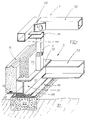
- Figure 1 shows parts of a rectangular base frame 3 and an overlying ceiling frame 4.
- the base frame 3 is composed of side members 32 and cross members 33. These are welded together in the corner.
- a double T profile 30 is used as the longitudinal beam 32, while the cross beam 33 consists of a U profile 37.
- a support 5 is welded onto the side member 32 and supports the ceiling frame 4 together with further supports. This advantageously consists of square tubes 35.
- a diagonal plate 49 as a stiffening element welded, which also has a crane eye for attaching a load hook or a load harness.
- FIG. 1 also shows a part of a strip foundation 22 with an overlying fixing plate 23.
- This serves as a secure support for the double-T support 30 and is connected to it in places by welding.
- the fixing plate 23 can in turn advantageously be cast into the strip foundation 22 with tie rods 40, 41 and firmly connected to it, as can be seen from FIGS. 6 and 8a.
- the outer wall-side flange of the double-T beam 30 carries, at intervals, welded, projecting flat bars 28 with vertical guide webs 26. These serve as brackets or supports for the outer wall cladding panels 15.
- These can preferably be lightweight concrete panels 15 made of porous or gas concrete or act as expanded clay and / or fly ash, fibers or wastes of concrete or plastics containing organic material.
- Such lightweight concrete slabs 15 provided for the outer wall cladding have, for example, a weight between 800 and 1800, preferably between 1100 and 1400 kg / m 3.
- the outer wall cladding can also be double-layered with a lightweight board arrangement 14 at a distance from the outer lightweight board 15. An air gap is then expediently left between the two plate arrangements.
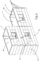
- FIG. 2 shows two buildings which are somewhat different in their individual design, which according to the invention consist of modules 1 to 1d arranged one on top of the other or one on top of the other.
- the building shown at the bottom right from the front side is composed of a total of five modules 1, 1a, 1b, 1c, 1d in cross-section and has a triple arrangement of these five modules in the longitudinal plane on, that is, the building is made up of a total of fifteen modules.
- These are covered with a common roof 9 and the building has a staircase 8 which can be assembled from prefabricated elements and which is arranged upstream of the building.
- the building shown on the left differs by a somewhat different individual arrangement of windows, doors or large window areas etc.
- the two buildings opposite of FIG. 2 are intended to show that the basic concept of the construction from individual modules 1 to 1d which can be put together offers a comparatively wide scope for individual design of the building.
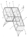
- FIGS. 3 and 4 a part of the building consisting of three modules 1 to 1b with partial cladding of the outer walls 10, 11 is shown from different perspective directions.
- the lightweight concrete panels 15 made of porous or gas concrete or other types of lightweight concrete mixtures provided for the outer wall cladding are clearly recognizable.
- These plates can be made to measure and individually numbered according to the construction plan and arranged on the outside of the steel skeleton 2.
- Bottom panel elements are dimensioned along the entire length of a module and across their width on the transverse side, while panel elements are arranged vertically next to window and door openings. Panels 16 provided as interior wall cladding can be seen next to the window openings.
- the plate elements 20 for the floors can also be seen from the viewing direction through the windows.
- Each module unit is equipped with complete electrical and sanitary installation as well as windows and doors.
- the plate elements 20 for the floor 6 can be provided with a screed 19.
- the modules are also suitable for extremely flexible expansion in terms of their equipment with doors, windows, installations, etc. For example, modules can also be set up as stair modules.
- FIG. 4 shows the part of the building in FIG. 3 from an opposite perspective, looking into the interior clad with interior wall elements 16.
- the floors 6 are formed with inserted gas concrete elements.
- This illustration also clearly shows the cladding of the outer walls 10 with lightweight panels 15.
- the abutting base and ceiling frames 3, 4 are coupled to one another by connecting elements, as can be seen in detail from FIGS. 8a, 8b.
- Figure 5 shows a bare steel skeleton 2 with base frame 3 and ceiling frame 4. These are rigidly connected to one another by supports 5. Gusset plates 24 are welded into the corner bandages for stabilization. The flat irons 28 welded in at intervals with guide webs 26 arranged thereon can be seen on the front double-T support 32. These serve the outer lightweight cladding panels 15 as supports for support.
- Figure 6 shows a section through parts of two stacked modules with their two base frames 3a and 3b.
- Plate elements 20a, 20b are inserted into the steel profiles 30a, 30b and covered with a screed 19a, 19b.
- the base frame 3a rests on a strip foundation 22 with a gravel bed 52, which is introduced into the soil 51 of the grown soil.
- a fixing plate 23 is arranged on the strip foundation 22 and fixed thereon with tie rods 40, 41.
- a window 44 is let into the outer wall 10.
- This has an outer frame 45 made of steel and the actual window inner frame 46 made of plastic and a schematically indicated double glazing.
- the flat irons 28a, 28b can be seen, on which the outer wall cladding panels 15 rest, guided by the guide webs 26a, 26b.
- the interior trim panels 16 are arranged and supported on the frame members 3a and 3b.
- a sound-absorbing, soft-elastic element 50 e.g. made of neoprene, rubber or similar against the spread of structure-borne noise.
- FIGS. 7a, 7b show corner connections between base frame 3 and support 5 from different perspectives.
- Welded-in gusset plates 24 are used for stabilization.
- Base frame 3 is each formed with double-T profiles 30.
- the flat irons 28 are shown with the guide webs 26 which receive the outer wall cladding panels 15 in a load-bearing manner.
- FIG. 7c shows a corner bond of the ceiling frame 4 with a support 5 in a completely welded design with gusset plates 24.
- Figure 8a shows two adjacent base frames 3 with a connection by a screwed tab 17.
- the two base frames have a common strip foundation 22 on which fixing plates 23 are arranged and firmly anchored with tie rods 40, 41.
- FIG. 8b shows frame elements 3, 4 which are assigned to modules which are arranged on one another or on top of one another.
- the figure shows the connection of the frame elements 3, 4 with horizontally and vertically arranged clamping screws 18a, 18b.
- Sound-absorbing intermediate layers 50 for example made of neoprene or rubber, are inserted between the frame parts 3 and 4 and provide insulation against the spread of structure-borne noise.
- FIG. 8c shows in detail a square tubular profile 35 of a ceiling frame 4 with a welded-on angle iron 36 and inserted ceiling plate element 21.
- the ceiling plate elements 21 can be inserted from above.
- the plate elements 20 for the floors can be done so that the base frame 3 on double-T beams 30 at one end remains open, then the gas-concrete floor slab elements 20 are inserted and finally a final double T-beam 30 is placed from the front and welded to the side members 32 of the base frame.
- the invention thus fulfills the task set out in an optimal solution.
Abstract
Description
Die Erfindung betrifft ein Gebäude, bestehend aus Modulen vorgefertigter Bauzellen.The invention relates to a building consisting of modules of prefabricated building cells.
Aus der DE-U1-88 07 893.0 ist ein Bausatz für ein transportables Wohnhaus bekannt. Dieser besteht aus zwei als geschlossene Hohlkörper mit Fenstern, Eingangstür und Durchgangsöffnungen ausgebildeten Wohneinheiten mit rechteckigem Grundriß, Dichtungselementen für die Abdichtung des Spaltes der aneinanderstoßenden Seiten der Wohneinheiten und einem Trailer zu Aufnahme einer Wohneinheit. Als nachteilig wird in diesem Zusammenhang der Spezial-Trailer empfunden, der nicht nur hohe Kosten verursacht, sondern an jedem Aufstellungsort Probleme für die Unterbringung sowie Schutz gegen Witterungseinflüsse verursacht.From DE-U1-88 07 893.0 a kit for a portable house is known. This consists of two housing units designed as closed hollow bodies with windows, entrance door and through openings with a rectangular layout, sealing elements for sealing the gap between the abutting sides of the housing units and a trailer for accommodating a housing unit. The special trailer is perceived as disadvantageous in this context, as it not only causes high costs, but also creates problems for accommodation and protection against weather influences at every installation site.
Aus der DE-U1-88 05 332.6 ist ein überdeckter Interims-Arbeitsplatz bekannt. Dieser wird von zwei längslaufenden, ein Dach tragende Wände gebildet, wobei sowohl die Wände wie auch das Dach vorgefertigte Montageteile sind. Bei den Wänden handelt es sich um Normcontainer, an deren Eckpfosten die aufzulegende vorgefertigte Dachkonstruktion aus Wellblech oder Trapezblechbahnen befestigbar ist. Die Normcontainer sind mit Türen und Fenstern versehene, begehbare Wohncontainer. Der überdeckte Interims-Arbeitsplatz dient der Unterbringung von Personal und Material an Baustellen und auch in Katastrophengebieten und ist speziell dafür konzipiert, einfach und schnell aufbaubar und ebenso schnell und einfach ohne große Kosten und ohne schwere Hebezeuge wieder entfernbar zu sein. Für Wohnzwecke ist der überdeckte Interims-Arbeitsplatz ungeeignet.A covered interim work station is known from DE-U1-88 05 332.6. This is formed by two longitudinal walls that support a roof, both the walls and the roof being prefabricated assembly parts. The walls are standard containers, on the corner posts of which the prefabricated roof structure made of corrugated iron or trapezoidal sheet metal sheets can be attached. The standard containers are walkable with doors and windows Residential container. The covered interim workstation is used to accommodate personnel and materials on construction sites and in disaster areas and is specially designed to be easy and quick to set up and just as quick and easy to remove again without great costs and without heavy lifting equipment. The covered interim workplace is unsuitable for residential purposes.
Der Erfindung liegt die Aufgabe zugrunde, aus vorgefertigten einzelnen Bauzellen preisgünstige Gebäude herzustellen, die infolge der vorgefertigten Raumeinheiten eine schnelle Montage vor Ort ermöglichen und bei kompletter Vorfertigung der zu einer Wohneinheit zusammenstellbaren Modulen den sogenannten "Containercharakter" vermeidet, infolge guter Wärmedämmwerte ein optimales Raumklima ermöglicht und eine weitgehend flexible Gestaltung nicht nur der Außenfassade, sondern des eigentlichen Wohnraumes bzw. Geschäftsraumes ermöglicht.The invention has for its object to produce inexpensive buildings from prefabricated individual building blocks, which, as a result of the prefabricated room units, enable rapid assembly on site and, with complete prefabrication of the modules which can be combined to form a residential unit, avoids the so-called "container character" and enables an optimal room climate as a result of good thermal insulation values and allows a largely flexible design not only of the outer facade, but of the actual living space or business space.
Zur Lösung der Aufgabe wird mit der Erfindung vorgeschlagen, daß jeder Modul eine zu einem Stahl-Skelett verschweißte, aus einem rechteckigen Grundrahmen, einem rechteckigen Deckenrahmen und vier vertikalen Stützen bestehende Rahmenkonstruktionen aufweist, deren Außenflächen und bedarfsweise auch Innenflächen mit Leichtbauplatten wärme- und schallisolierend verkleidet und deren Böden und Decken mit vorgefertigten, selbsttragenden, in von Stahlprofilen des Grund- bzw. Deckenrahmens gebildete Führungen einschiebbaren Plattenelementen aus Beton ausgebildet sind.To solve the problem it is proposed with the invention that each module has a welded to a steel skeleton, consisting of a rectangular base frame, a rectangular ceiling frame and four vertical supports frame structures, the outer surfaces and, if necessary, also the inner surfaces are clad with heat-insulating and sound-insulating panels and the floors and ceilings of which are made of prefabricated, self-supporting plate elements made of concrete that can be inserted into guides formed by steel profiles of the base or ceiling frame.
Die erfindungsgemäße vorgefertigte Ausführung der Module in Rahmenkonstruktion und deren äußere und innere Auskleidung mit Leichtbauplatten sowie der Einbau von Böden und Decken unter Verwendung einschiebbarer Plattenelemente ermöglicht mit Vorteil deren ungewöhnlich schnelle Montage vor Ort und ergibt Gebäude mit wohnlichem Flair ohne Containercharakter mit optimalen Raumklima infolge überraschend guter Wärmedämmwerte. Weiterhin ist eine flexible Gestaltung der Außenfassade und eine mehrgeschossige Ausführung der Gebäude bei außerordentlich günstigen Erstellungskosten möglich. Diese bewegen sich im Rahmen vorliegender Kalkulationen bei etwa 50 % der üblichen Baukosten je Kubikmeter umbautem Raum.The prefabricated design of the modules according to the invention in frame construction and their outer and inner lining with lightweight building boards and the installation of floors and ceilings using insertable plate elements advantageously enables their unusually quick installation on site and results in buildings with a homely flair without container character with an optimal indoor climate as a result of surprisingly good Thermal insulation values. It is also flexible Design of the outer facade and a multi-storey version of the building possible at extremely low construction costs. In the context of the present calculations, these are around 50% of the usual construction costs per cubic meter of converted space.
Eine Ausgestaltung sieht vor, daß die Plattenelemente mit Vorspannmitteln bzw. mit Moniereisen armierte Leichtbetonplatten sind. Dabei können die zur Außenwandverkleidung vorgesehenen Platten Leichtbetonplatten aus Poren- oder Gasbeton bzw. Blähton und/oder Flugasche, Fasern oder Abfälle von Kunststoff oder organischem Material enthaltendem Beton sein. So ist bspw. aus der EP-0 208 070 B1 ein Verfahren bekannt, mit welchem raumbeständige, gegen Wasser und Frost beständige Bauelemente mit hoher Wärmedämmung in wirtschaftlicher Weise herstellbar sind. Die Bauelemente weisen eine Trockenrohdichte von 500 bis 800 Kg/m³ auf. Je nach Art der Zuschlagsstoffe, bspw. bei Verwendung von Blähton oder Flugasche, können die für die Außenverkleidung vorgesehenen Leichtbetonplatten ein Gewicht zwischen 800 und 1800, vorzugsweise zwischen 1100 und 1400 Kg/m³ aufweisen. Weiterhin können auch die für die Innenwandverkleidung vorgesehenen Platten aus Leichtbeton bestehen. Entsprechend einer zweckmäßigen Ausgestaltung der Erfindung ist vorgesehen, daß die Innenwand-Verkleidungsplatten aus Gips gebundenen Plattenwerkstoffen bestehen und bspw. Gips-Faser-Gemischplatten, Gips-Kartonplatten, Gips-Schaumstoffplatten mit poriger Struktur oder aus ähnlichen bekannten Gips-Baustoffen sind und ein Gewicht zwischen 450 und 800, vorzugsweise zwischen 550 und 750 Kg/m³ aufweisen. Es können aber auch Platten verwendet werden, welche aus zumindest 80 % recycelten Kunststoffabfällen bestehen.One embodiment provides that the plate elements are reinforced concrete plates reinforced with pretensioning means or with monier iron. The panels provided for the outer wall cladding can be lightweight concrete panels made of porous or gas concrete or expanded clay and / or fly ash, fibers or waste concrete containing plastic or organic material. For example, a method is known from EP-0 208 070 B1 with which spatially stable, water and frost resistant components with high thermal insulation can be produced economically. The components have a dry bulk density of 500 to 800 kg / m³. Depending on the type of aggregate, for example when using expanded clay or fly ash, the lightweight concrete slabs provided for the outer cladding can have a weight between 800 and 1800, preferably between 1100 and 1400 kg / m³. Furthermore, the panels provided for the interior wall cladding can also consist of lightweight concrete. According to an expedient embodiment of the invention, it is provided that the inner wall cladding panels consist of gypsum-bound panel materials and, for example, gypsum-fiber mixed panels, gypsum cardboard panels, gypsum foam panels with porous structure or from similar known gypsum building materials and a weight between 450 and 800, preferably between 550 and 750 kg / m³. However, plates can also be used which consist of at least 80% recycled plastic waste.
Eine Verwendung derart leichtgewichtiger Außen- bzw. Innenplatten ist deshalb möglich, weil das Stahl-Skelett eines jeden Moduls die Statik übernimmt, wogegen die Platten ausschließlich das nicht tragende Bauteil am Stahl-Skelett befestigt und ggfs. an Halterungen aufgehängt sind.The use of such light-weight outer and inner panels is possible because the steel skeleton of each module takes over the statics, whereas the panels only fix the non-load-bearing component to the steel skeleton and are possibly hung on brackets.
Eine Ausgestaltung sieht vor, daß ein nach der Erfindung herstellbares Gebäude aus einer beliebigen Aneinanderreihung einer Anzahl von Modulen in einer oder mehreren fallweise auch terrassenförmigen Ebenen und/oder einer Aufeinanderstellung von Modulen in vertikal beabstandeten Ebenen besteht.One embodiment provides that a building that can be produced according to the invention consists of any desired sequence of a number of modules in one or more, in some cases also terrace-shaped levels and / or a stacking of modules in vertically spaced levels.
Erfindungswesentlich sind mehrere ein Gebäude bildende Stahl-Skelette durch Zuganker mit im Maschinen- bzw. Stahlbau üblichen Verbindungselementen verbunden.Essential to the invention, several steel skeletons forming a building are connected by tie rods with connecting elements which are customary in mechanical or steel construction.
Mit großem Vorteil ist erfindungsgemäß vorgesehen, daß Verkleidungsplatten für Innenwände mit integrierten Zu- und Ableitungen für Strom und Wasser als Fertigbauteile ausgebildet sind. Durch diese Maßnahme wird der vor Ort erforderliche Montageaufwand auf ein absolutes Minimum reduziert.It is provided with great advantage according to the invention that cladding panels for inner walls with integrated supply and discharge lines for electricity and water are designed as prefabricated components. This measure reduces the assembly effort required on site to an absolute minimum.
Eine Ausgestaltung sieht weiter vor, daß der Grundrahmen eines Stahl-Skeletts zum Rechteck miteinander verschweißte Doppel-T-Längs- und Querträger aufweist, beispielsweise IPB 160, deren untere außenwandseitige Flansche in Abständen angeschweißte, auskragende Flacheisen mit vertikalen Führungstegen aufweisen, welche als Halterungen für auflegbare Außenwand-Verkleidungsplatten ausgebildet sind. Durch diese Maßnahme wird die Anbringung der Verkleidungsplatten fallweise für Außenwände, aber auch für Innenwände, außerordentlich vereinfacht. Dadurch können bei der Montage auf Maß bestellte beispielsweise Porenbeton-Elemente an den vorhandenen Halterungen ohne Schwierigkeiten angebracht werden.One embodiment further provides that the base frame of a steel skeleton has a double-T longitudinal and transverse beam welded together to form a rectangle, for example IPB 160, the lower flanges of which on the outer wall have welded-on, protruding flat bars with vertical guide bars, which serve as holders for outer wall cladding panels that can be placed are formed. This measure greatly simplifies the installation of the cladding panels for outer walls, but also for inner walls. As a result, for example, aerated concrete elements ordered to size can be attached to the existing brackets without difficulty.
Eine zweckmäßige Ausgestaltung sieht vor, daß als Querträger zwischen die Flansche der Doppel-T-Längsträger einpaßbare U-Profilträger beispielsweise U 160, eingeschweißt sind.An expedient embodiment provides that U-profile supports, for example U 160, are welded in as cross-members between the flanges of the double-T longitudinal members.
Weiterhin ist vorgesehen, daß der Deckenrahmen aus Vierkant-Rohren besteht, an welche in Abständen nach innen weisende und als Auflager für die Deckenplatten ausgebildete Winkeleisen vorgeschweißt sind.It is further provided that the ceiling frame consists of square tubes, to which angle irons pointing inwards and formed as supports for the ceiling panels are pre-welded.
Eine sehr zweckmäßige Ausgestaltung eines nach der Erfindung aus Modulen hergestellten Gebäudes sieht vor, daß diesem ein aus vorgefertigten Elementen zusammenmontierbares Treppenhaus vorgeordnet ist. Dadurch erhält das Haus den Charakter und das Aussehen eines üblichen Wohnhauses, welches sich von übliche Wohnhaus- oder Geschäftsbauten auch äußerlich kaum unterscheidet. Dieser Eindruck wird weiterhin noch dadurch verstärkt, daß das Gebäude mit einem Dach üblicher Bauart abdeckbar ist.A very expedient embodiment of a building made from modules according to the invention provides that a staircase which can be assembled from prefabricated elements is arranged upstream. This gives the house the character and appearance of a normal residential building, which hardly differs in appearance from conventional residential or commercial buildings. This impression is further reinforced by the fact that the building can be covered with a roof of the usual type.
Zweckmäßig ist dem Grundrahmen ein Streifenfundament zugeordnet, welches eine im Fundament verankerte bzw. eingegossene Auflage- und Fixierungsplatte aus Stahl trägt.A base is expediently assigned to the base frame, which carries a steel anchoring and fixing plate anchored or cast into the foundation.
Und schließlich ist vorgesehen, daß aneinander oder aufeinander gesetzte Modulen durch Zwischenlagen aus schalldämmendem, weichelastischem Material wie Neoprene, Gummi o.ä. gegen Ausbreitung von Körperschall gegenseitig isoliert sind.Finally, it is envisaged that modules placed one on top of the other or on top of each other by intermediate layers made of sound-absorbing, soft-elastic material such as neoprene, rubber or the like are mutually insulated against the spread of structure-borne noise.
Die Erfindung wird in schematischen Zeichnungen in bevorzugten Ausführungsformen gezeigt, wobei aus den Zeichnungen weitere vorteilhafte Einzelheiten der Erfindung entnehmbar sind. Es zeigen:
Figur 1- in perspektivischer Darstellung Teile der Hauptelemente eines Stahl-Skeletts für eine Bauzelle
Figur 2- nach der Erfindung hergestellte Gebäude in Ansichten aus unterschiedlichen Richtungen,
Figur 3- eine aus drei Modulen zusammengesetzte Gebäudeeinheit, in perspektivischer Darstellung,
Figur 4- die Gebäudeeinheit gemäß Fig. 3 in perspektivischer Darstellung mit Einblick in das teilweise noch unverkleidete Innere,
Figur 5- ebenfalls in Parallelperspektive ein Stahl-Skelett für ein Modul, fertig zum Einschieben der Boden- und Deckenelemente sowie zum Auskleiden der Wände,
Figur 6- im Schnitt einen Teil eines zweistöckigen Gebäudes,
- Figur 7a bis 7c
- perspektivische Darstellungen der Rahmenkonstruktion und insbesondere der Eckverbände,
- Figur 8a und 8b
- Laschenverbindungen von Fundament- und Deckenrahmen,
- Figur 8c
- einen Schnitt des Auflagers für das Dach-Plattenelement.
- Figure 1
- a perspective view of parts of the main elements of a steel skeleton for a building cell
- Figure 2
- Buildings manufactured according to the invention in views from different directions,
- Figure 3
- a building unit composed of three modules, in perspective,
- Figure 4
- 3 in perspective view with a view of the partially still unclad interior,
- Figure 5
- also in parallel perspective a steel skeleton for a module, ready to insert the floor and ceiling elements and to line the walls,
- Figure 6
- on average part of a two-story building,
- Figure 7a to 7c
- perspective representations of the frame construction and in particular the corner bandages,
- Figures 8a and 8b
- Tab connections of foundation and ceiling frames,
- Figure 8c
- a section of the support for the roof panel element.
Figur 1 zeigt Teile eines rechteckigen Grundrahmens 3 und eines darüberliegenden Deckenrahmens 4. Der Grundrahmen 3 setzt sich aus Längsträgern 32 und Querträgern 33 zusammen. Diese sind in der Ecke miteinander verschweißt. Als Längsträger 32 ist ein Doppel-T-Profil 30 verwendet, während der Querträger 33 aus einem U-Profil 37 besteht. Auf dem Längsträger 32 ist eine Stütze 5 aufgeschweißt, welche zusammen mit weiteren Stützen den Deckenrahmen 4 trägt. Dieser besteht vorteilhaft aus Vierkant-Rohren 35. In die Ecke des Deckenrahmens 4 ist als Versteifungselement ein Diagonalblech 49 eingeschweißt, welches zugleich eine Kranöse zum Anschlagen eines Lasthakens oder eines Lastgeschirrs aufweist.Figure 1 shows parts of a
Figur 1 zeigt weiterhin einen Teil eines Streifenfundamentes 22 mit einer aufliegenden Fixierungsplatte 23. Diese dient der sicheren Auflage für den Doppel-T-Träger 30 und ist mit diesem stellenweise durch Schweißung verbunden. Die Fixierungsplatte 23 kann ihrerseits zweckmäßig mit Zugankern 40, 41 in das Streifenfundament22 eingegossen und mit diesem fest verbunden sein, wie dies aus den Figuren 6 bzw. 8a erkannbar ist.FIG. 1 also shows a part of a
Der außenwandseitige Flansch des Doppel-T-Trägers 30 trägt in Abständen angeschweißte, auskragende Flacheisen 28 mit vertikalen Führungsstegen 26. Diese dienen als Halterungen bzw. Auflagen für die Außenwand-Verkleidungsplatten 15. Es kann sich hierbei vorzugsweise um Leichtbetonplatten 15 aus Poren- oder Gasbeton bzw. Blähton- und/oder Flugasche, Fasern oder Abfälle von Kunststoffen oder organischem Material enthaltendem Beton handeln. Solche, für die Außenwandverkleidung vorgesehene Leichtbetonplatten 15 haben bspw. ein Gewicht zwischen 800 und 1800, vorzugsweise zwischen 1100 und 1400 Kg/m³.The outer wall-side flange of the double-
Bei höheren Ansprüchen an Wärmedämmung bzw. Isolation des Gebäudes kann die Außenwandverkleidung auch doppelschichtig mit einer Leichtbauplatten-Anordnung 14 im Abstand von der äußeren Leichtbauplatte 15 sein. Zweckmäßig ist dann zwischen beiden Plattenanordnungen ein Luftspalt freigelassen.For higher demands on thermal insulation or insulation of the building, the outer wall cladding can also be double-layered with a
Figur 2 zeigt zwei in ihrer individuellen Gestaltung etwas unterschiedliche Gebäude, die nach der Erfindung aus einander oder aufeinander angeordneten Modulen 1 bis 1d bestehen. Das rechts unten von der Stirnseite her gezeigte Gebäude ist im Querschnitt aus insgesamt fünf Modulen 1, 1a, 1b, 1c, 1d zusammengesetzt und weist in der Längsebene eine Dreifach-Anordnung dieser jeweils fünf Module auf, das heißt, daß Gebäude ist aus insgesamt fünfzehn Modulen zusammengesetzt bzw. aufgebaut. Diese sind mit einem gemeinsamen Dach 9 überdeckt und das Gebäude weist ein aus vorgefertigten Elementen zusammenmontierbares Treppenhaus 8 auf, welches dem Gebäude seitlich vorgeordnet ist. Das linksseitig dargestellte Gebäude unterscheidet sich durch eine etwas andere individuelle Anordnung von Fenstern, Türen oder Großfensterflächen etc.. Die beiden gegenübergestellten Gebäude der Figur 2 sollen zeigen, daß das Grundkonzept der Bauweise aus einzelnen zusammenstellbaren Modulen 1 bis 1d einen vergleichsweise weiten Spielraum für individuelle Ausgestaltung des Gebäudes ermöglicht.FIG. 2 shows two buildings which are somewhat different in their individual design, which according to the invention consist of
In den Figuren 3 und 4 ist aus jeweils anderen perspektivischen Richtungen ein aus drei Modulen 1 bis 1b bestehender Gebäudeteil mit teilweiser Verkleidung der Außenwände 10, 11 gezeigt. Deutlich erkennbar sind die zur Außenwandverkleidung vorgesehenen Leichtbetonplatten 15 aus Poren- oder Gasbeton bzw. anderen Arten von Leichtbetonmischungen. Diese Platten können auf Maß gefertigt und nach Bauplan einzeln nummeriert passend an der Außenseite des Stahl-Skelettes 2 angeordnet werden. Dabei sind untere Plattenelemente in ganzer Länge eines Moduls und an der Querseite in ganzer Breite bemessen, während neben Fenster- und Türöffnungen Plattenelemente senkrecht angeordnet sind. Als Innenwandverkleidung vorgesehene Platten 16 sind neben den Fensteröffnungen zu erkennen. Schließlich sind aus der Blickrichtung durch die Fenster hindurch auch die Plattenelemente 20 für die Böden zu erkennen. Jede Moduleinheit ist mit kompletter elektrischer und sanitärer Installation sowie mit Fenstern und Türen ausgestattet. Entsprechend einer Darstellung in Figur 6 können die Plattenelemente 20 für den Boden 6 mit einem Estrich 19 versehen sein. Die Module sind im übrigen hinsichtlich ihrer Ausstattung mit Türen, Fenstern, Installationen etc. für einen äußerst flexiblen Ausbau geeignet. So können bspw. auch Module als Treppenmodule eingerichtet sein.In FIGS. 3 and 4, a part of the building consisting of three
Figur 4 zeigt den Gebäudeteil der Figur 3 aus entgegengesetzter Perspektive mit Blick in das mit Innenwandelementen 16 verkleidete Innere. Die Böden 6 sind mit eingelegten Gasbetonelementen ausgebildet. Deutlich zeigt auch diese Darstellung die Verkleidung der Außenwände 10 mit Leichtbauplatten 15. Die aneinanderstoßenden Grund- und Deckenrahmen 3, 4 sind durch Verbindungselemente aneinandergekoppelt, wie diese im einzelnen aus der Figur 8a, 8b erkennbar sind.FIG. 4 shows the part of the building in FIG. 3 from an opposite perspective, looking into the interior clad with
Figur 5 zeigt ein nacktes Stahl-Skelett 2 mit Grundrahmen 3 und Deckenrahmen 4. Diese sind durch Stützen 5 miteinander starr verbunden. In die Eckverbände sind Knotenbleche 24 zwecks Stabilisierung eingeschweißt. An dem vorderen Doppel-T-Träger 32 sind die in Abständen eingeschweißten Flacheisen 28 mit daran angeordneten Führungsstegen 26 erkennbar. Diese dienen den äußeren Leichtbau-Verkleidungsplatten 15 als Halterungen zur Auflage.Figure 5 shows a
Figur 6 zeigt einen Schnitt durch Teile zweier aufeinandergestellter Module mit deren beiden Grundrahmen 3a und 3b. In die Stahlprofile 30a, 30b sind jeweils Plattenelemente 20a, 20b eingeschoben und mit einem Estrich 19a, 19b überschichtet. Der Grundrahmen 3a ruht auf einem Streifenfundament 22 mit Kiesbett 52, welches in das Erdreich 51 des gewachsenen Bodens eingebracht ist. Auf dem Streifenfundament 22 ist eine Fixierungsplatte 23 angeordnet und mit Zugankern 40, 41 auf diesem fixiert. In die Außenwand 10 ist ein Fenster 44 eingelassen. Dieses weist einen Außenrahmen 45 aus Stahl sowie den eigentlichen Fenster-Innenrahmen 46 aus Kunststoff und eine schematisch angedeutete Doppelverglasung auf. Weiterhin sind an den Profilen 30a, 30b an deren Außenflanschen die Flacheisen 28a, 28b zu sehen, auf welchen unter Führung durch die Führungsstege 26a, 26b die Außenwand-Verkleidungsplatten 15 aufliegen. In ähnlicher Weise sind die Innenverkleidungsplatten 16 angeordnet und auf den Rahmenelementen 3a bzw. 3b abgestützt. In die obere Ecke unterhalb des Rahmens 3b ist ein schalldämmendes, weichelastisches Element 50 bspw. aus Neopren, Gummi o.ä. gegen Ausbreitung von Körperschall eingelassen.Figure 6 shows a section through parts of two stacked modules with their two
Die Figuren 7a, 7b zeigen aus unterschiedlichen Perspektiven Eckverbindungen zwischen Grundrahmen 3 und Stütze 5. Zur Stabilisierung dienen eingeschweißte Knotenbleche 24. Der Grundrahmen 3 ist jeweils mit Doppel-T-Profilen 30 ausgebildet. An deren äußeren, unteren Flanschen 31 sind die Flacheisen 28 mit den Führungsstegen 26 gezeigt, welche die Außenwand-Verkleidungsplatten 15 tragend aufnehmen.FIGS. 7a, 7b show corner connections between
Figur 7c zeigt einen Eckverband des Deckenrahmens 4 mit einer Stütze 5 in vollständig verschweißter Ausführung mit Knotenblechen 24.FIG. 7c shows a corner bond of the
Figur 8a zeigt zwei nebeneinanderliegende Grundrahmen 3 mit einer Verbindung durch eine verschraubte Lasche 17. In diesem Falle weisen die beiden Grundrahmen ein gemeinsames Streifenfundament 22 auf, auf welchem Fixierungsplatten 23 angeordnet und mit Zugankern 40, 41 fest verankert sind.Figure 8a shows two adjacent base frames 3 with a connection by a screwed
Figur 8b zeigt Rahmenelemente 3, 4, welche aneinander bzw. aufeinander angeordneten Modulen zugeordnet sind. Die Figur zeigt die Verbindung der Rahmenelemente 3, 4 mit horizontal und vertikal angeordneten Spannschrauben 18a, 18b. Zwischen den Rahmenteilen 3 und 4 sind schalldämmende Zwischenlagen 50 bspw. aus Neoprene oder Gummi eingelegt und ergeben eine Isolierung gegen Ausbreitung von Körperschall.FIG. 8b shows
Schließlich zeigt Figur 8c im Detail ein Vierkant-Rohrprofil 35 eines Deckenrahmens 4 mit angeschweißtem Winkeleisen 36 und eingelegtem Decken-Plattenelement 21. Bei dieser Ausgestaltung können die Decken-Plattenelemente 21 von oben eingelegt werden. Bei den Plattenelementen 20 für die Böden kann so verfahren werden, daß der Grundrahmen 3 auf Doppel-T-Trägern 30 an einer Stirnseite zunächst offen bleibt, sodann die Gasbeton-Bodenplattenelemente 20 eingeschoben werden und zuletzt ein Abschluß-Doppel-T-Träger 30 von der Stirnseite her vorgelegt und mit den Längsträgern 32 des Grundrahmens verschweißt wird.Finally, FIG. 8c shows in detail a square
Die Erfindung ergibt insgesamt folgende Vorteile:
- Komplette Vorfertigung im Werk.
- Schnelle Montage vor Ort durch vorgefertigte Raumeinheiten.
- Optimales Raumklima, sehr gute Dämmwerte.
- Mehrgeschossige Anlagen durch beliebige Aneinanderreihung von Modulen.
- Rasche und unkomplizierte Verkleidung der Außen- und Innenwände durch vorgefertigte Porenbeton-Plattenelemente.
- Vermeidung eines primitiven "Containercharakters".
- Flexible Gestaltung der Außenfassade sowie des Innenausbaus.
- Sehr gute Witterungsbeständigkeit.
- Halbierung der Baukosten gegenüber konventionellen Bauausführungen.
- Complete prefabrication in the factory.
- Fast assembly on site thanks to prefabricated room units.
- Optimal room climate, very good insulation values.
- Multi-storey systems through any row of modules.
- Quick and uncomplicated cladding of the outer and inner walls thanks to prefabricated aerated concrete panel elements.
- Avoiding a primitive "container character".
- Flexible design of the outer facade and the interior.
- Very good weather resistance.
- Halving of construction costs compared to conventional construction.
Somit erfüllt die Erfindung in optimaler Lösung die eingangs gestellte Aufgabe.The invention thus fulfills the task set out in an optimal solution.
- 11
- Modulmodule
- 22nd
- Stahl-SkelettSteel skeleton
- 33rd
- GrundrahmenBase frame
- 44th
- DeckenrahmenCeiling frame
- 55
- StützenSupport
- 66
- Bodenground
- 77
- Deckeceiling
- 88th
- TreppenhausStairwell
- 99
- Dachtop, roof
- 1010th
- Außenfläche/WandOutside surface / wall
- 1111
- Außenfläche/WandOutside surface / wall
- 1212th
- Innenfläche/WandInner surface / wall
- 1313
- Innenfläche/WandInner surface / wall
- 1414
- Leichtbauplatte außenLightweight construction board outside
- 1515
- Leichtbauplatte außenLightweight construction board outside
- 1616
- Leichtbauplatte innenLightweight board inside
- 1717th
- LascheTab
- 1818th
- SpannschraubenTurnbuckles
- 1919th
- EstrichScreed
- 2020th
- Plattenelement/BodenPanel element / floor
- 2121
- Plattenelement/DeckePanel element / ceiling
- 2222
- StreifenfundamentStrip foundation
- 2323
- FixierungsplatteFixation plate
- 2424th
- KnotenblecheGusset plates
- 2626
- Führungsstege/GrundrahmenGuide bars / base frame
- 2828
- Flacheisen/GrundrahmenFlat iron / base frame
- 2929
- Flansche/Doppel-T-TrägerFlanges / double T-beams
- 3030th
- Stahlprofil/Grundrahmen/Doppel-T-TrägerSteel profile / base frame / double T-beam
- 3131
- Stahlprofil/AußenflanschSteel profile / outer flange
- 3232
- Längsträger/GrundrahmenSide member / base frame
- 3333
- Längsträger/DeckenrahmenSide member / ceiling frame
- 3434
- QuerträgerCross member
- 3535
- Vierkant-Rohre/DeckeSquare tubes / ceiling
- 3636
- WinkeleisenAngle iron
- 3737
- U-ProfilU profile
- 4040
- ZugankerTie rod
- 4141
- ZugankerTie rod
- 4444
- Fensterwindow
- 4545
- AußenrahmenOuter frame
- 4646
- InnenrahmenInner frame
- 4747
- Führungguide
- 4949
- DiagonalblechDiagonal sheet
- 5050
- Zwischenanlage/SchalldämmungIntermediate system / sound insulation
- 5151
- gewachsener Boden/Erdreichgrown soil
- 5252
- KiesbettGravel bed
Claims (20)
dadurch gekennzeichnet,
daß jeder Modul (1) eine zu einem Stahl-Skelett (2) verschweißte, aus einem rechteckigen Grundrahmen (3), einem rechteckigen Deckenrahmen (4) und vier vertikalen Stützen (5) bestehende Rahmenkonstruktion aufweist, deren Außenflächen (10 bzw. 11) und bedarfsweise auch Innenflächen (12 bzw. 13) mit Leichtbauplatten (14, 15, 16) wärme- und schallisolierend verkleidet und deren Böden (6) und Decken (7) mit vorgefertigten selbsttragenden, in von Stahlprofilen (30) des Grund- bzw. Deckenrahmens (3, 4) gebildete Führungen (47) einschiebbaren Plattenelementen (20, 21) aus Beton ausgebildet sind.Buildings consisting of modules of prefabricated building cells,
characterized,
that each module (1) has a frame structure welded to a steel skeleton (2), consisting of a rectangular base frame (3), a rectangular ceiling frame (4) and four vertical supports (5), the outer surfaces (10 and 11) of which and if necessary also inner surfaces (12 or 13) are clad with heat-insulating and sound-insulating panels (14, 15, 16) and their floors (6) and ceilings (7) are prefabricated with self-supporting steel profiles (30) of the base or Ceiling frame (3, 4) formed guides (47) insertable plate elements (20, 21) are made of concrete.
dadurch gekennzeichnet,
daß die Plattenelemente (20, 21) mit Vorspannmitteln bzw. mit Moniereisen armierte Leichtbetonplatten sind.Building according to claim 1,
characterized,
that the plate elements (20, 21) are pre-stressed or reinforced with light iron reinforced concrete slabs.
dadurch gekennzeichnet,
daß die zur Außenwandverkleidung vorgesehenen Platten Leichtbetonplatten (15) aus Poren- bzw. Gasbeton bzw. Blähton und/oder Flugasche, Fasern oder Abfälle von Kunststoffen oder organischem Material enthaltendem Beton sind.Building according to claim 1 or 2,
characterized,
that the slabs provided for the outer wall cladding are lightweight concrete slabs (15) made of porous or gas concrete or expanded clay and / or fly ash, fibers or waste concrete containing plastics or organic material.
dadurch gekennzeichnet,
daß die für die Außenverkleidung vorgesehenen Leichtbetonplatten (15) ein Gewicht zwischen 800 und 1800, vorzugsweise zwischen 1100 und 1400 Kg/m³ aufweisen.Building according to one of claims 1 to 3,
characterized,
that the lightweight concrete slabs (15) provided for the outer cladding have a weight between 800 and 1800, preferably between 1100 and 1400 kg / m³.
dadurch gekennzeichnet,
daß die für die Innenwandverkleidung vorgesehenen Platten (16) aus Leichtbeton bestehen.Building according to one or more of claims 1 to 4,
characterized,
that the plates (16) provided for the inner wall cladding consist of lightweight concrete.
dadurch gekennzeichnet,
daß die Innenwand-Verkleidungsplatten (16) aus gipsgebundenen Plattenwerkstoffen bestehen und bspw. Gips-Faser-Gemischplatten, Gipskartonplatten, Gipsschaumstoffplatten mit poriger Struktur oder aus ähnlichen bekannten Gipsbaustoffen sind.Building according to one or more of claims 1 to 4,
characterized,
that the inner wall cladding panels (16) consist of gypsum-bonded panel materials and are, for example. Gypsum-fiber mixed panels, plasterboard panels, gypsum foam panels with a porous structure or from similar known gypsum building materials.
dadurch gekennzeichnet,
daß aus Gipsbaustoffen bestehende Innenwand-Verkleidungsplatten (16) ein Gewicht zwischen 450 und 800, vorzugsweise zwischen 550 und 750 Kg/m³ aufweisen.Building according to one or more of claims 1 to 6,
characterized,
that consisting of plasterboard inner wall cladding panels (16) have a weight between 450 and 800, preferably between 550 and 750 kg / m³.
dadurch gekennzeichnet,
daß Verkleidungsplatten (15, 16) aus zumindest 80 % recycelten Kunststoffabfällen bestehen.Building according to one or more of claims 1 to 7,
characterized,
that cladding panels (15, 16) consist of at least 80% recycled plastic waste.
dadurch gekennzeichnet,
daß es aus einer beliebigen Aneinanderreihung einer Anzahl von Modulen in einer oder mehreren fallweise auch terassenförmigen Ebenen (x-x) und/oder einer Aufeinanderstellung von Modulen (1, 1a, 1b) in vertikal beabstandeten Ebenen (y-y) besteht.Building according to one or more of claims 1 to 8,
characterized,
that it consists of an arbitrary sequence of a number of modules in one or more case-by-case also terrace-shaped levels (xx) and / or a stack of modules (1, 1a, 1b) in vertically spaced levels (yy).
dadurch gekennzeichnet,
daß mehrere ein Gebäude bildende Stahl-Skelette (2) durch Zuganker (40, 41) mit im Maschinen bzw. Stahlbau üblichen Verbindungselementen verbunden sind.Building according to one or more of claims 1 to 9,
characterized,
that several steel skeletons (2) forming a building are connected by tie rods (40, 41) with connecting elements customary in machine or steel construction.
dadurch gekennzeichnet,
daß Verkleidungsplatten (16) für Innenwände (12, 13) mit integrierten Zu- und Ableitungen (nicht gezeigt) für Strom und Wasser als Fertigbauteile ausgebildet sind.Building according to one or more of claims 1 to 10,
characterized,
that cladding panels (16) for inner walls (12, 13) with integrated supply and discharge lines (not shown) for electricity and water are designed as prefabricated components.
dadurch gekennzeichnet,
daß der Grundrahmen (3) eines Stahl-Skelettes (2) zum Rechteck miteinander verschweißte Doppel-T-Längs- und Querträger (30) aufweist, bspw. IPB 160, deren untere außenwandseitigen Flansche (31) in Abständen angeschweißte, auskragende Flacheisen (28) mit vertikalen Führungsstegen (26) aufweisen, welche als Halterungen für auflegbare Außenwand-Verkleidungsplatten (15) ausgebildet sind.Building according to one or more of claims 1 to 11,
characterized,
that the base frame (3) of a steel skeleton (2) has a double-T longitudinal and cross member (30) welded together to form a rectangle, for example IPB 160, the lower flanges (31) of which are welded at intervals on the outside and projecting flat bars (28 ) with vertical guide webs (26), which are designed as brackets for outer wall cladding panels (15).
dadurch gekennzeichnet,
daß die Längsträger (32) des Grundrahmens (3) an einer Stirnseite mit einem Querträger (33) fest verschweißt sind, wogegen der Querträger (34) der anderen Stirnseite unter Verwendung im Maschinen- oder Stahlbau üblicher lösbarer Verbindungsmittel mit den Längsträgern (32) verbindbar ist.Building according to one or more of claims 1 to 12,
characterized,
that the side members (32) of the base frame (3) are firmly welded on one end face to a cross member (33), whereas the cross member (34) of the other end face can be connected to the side members (32) using releasable connecting means that are common in mechanical engineering or steel construction is.
dadurch gekennzeichnet,
daß als Querträger (33 bzw. 34) zwischen die Flansche (29) der Doppel-T-Längsträger (32) einpaßbare U-Profilträger, bspw. U 160, eingeschweißt sind.Building according to one or more of claims 1 to 13,
characterized,
that as a cross member (33 or 34) between the flanges (29) of the double-T longitudinal members (32) are fitable U-profile members, for example U 160, welded.
dadurch gekennzeichnet,
daß der Deckenrahmen (4) aus Vierkant-Rohren (35) besteht, an welche in Abständen nach innen weisende und als Auflager für die Deckenplatten (21) ausgebildete Winkeleisen (36) vorgeschweißt sind.Building according to one or more of claims 1 to 14,
characterized,
that the ceiling frame (4) consists of square tubes (35), to which angle bars (36) are welded inward at intervals and are designed as supports for the ceiling panels (21).
dadurch gekennzeichnet,
daß diesem ein aus vorgefertigten Elementen zusammenmontierbares Treppenhaus (8) vorgeordnet ist.Building according to one or more of claims 1 to 15,
characterized,
that this is preceded by a pre-assembled elements assembled staircase (8).
dadurch gekennzeichnet,
daß es mit einem Dach (9) abdeckbar ist.Building according to one or more of claims 1 to 16,
characterized by
that it can be covered with a roof (9).
dadurch gekennzeichnet,
daß dem Grundrahmen (3) ein Streifenfundament (22) zugeordnet ist, welches eine im Fundament verankerte bzw. eingegossene Auflage- und Fixierungsplatte aus Stahl (23) trägt.Building according to one or more of claims 1 to 17,
characterized,
that the base frame (3) is assigned a strip foundation (22) which carries an anchored or cast-in support and fixing plate made of steel (23).
dadurch gekennzeichnet,
daß aneinander oder aufeinander angeordnete Module (1a, 1b, 1c etc.) durch Zwischenlagen (15) aus schalldämmendem weichelastischem Material wie Neoprene, Gummi o.ä. gegen Ausbreitung von Körperschall gegenseitig isoliert sind.Building according to one or more of claims 1 to 18,
characterized,
that modules (1a, 1b, 1c etc.) arranged one on top of the other or on top of each other by intermediate layers (15) made of sound-absorbing, soft-elastic material such as neoprene, rubber or the like. are mutually insulated against the spread of structure-borne noise.
dadurch gekennzeichnet,
daß die Außenwandverkleidung eines Moduls (1) mehrschichtig mit einer Leichtbauplatten-Anordnung (14, 15) mit zwischen den Platten (14, 15) befindlichem Isolierspalt ausgebildet ist.Building according to one or more of claims 1 to 19,
characterized,
that the outer wall cladding of a module (1) is constructed in several layers with a lightweight building board arrangement (14, 15) with an insulating gap located between the boards (14, 15).
Applications Claiming Priority (3)
| Application Number | Priority Date | Filing Date | Title |
|---|---|---|---|
| DE9312109U | 1993-08-13 | ||
| DE9312109U DE9312109U1 (en) | 1993-08-13 | 1993-08-13 | Building consisting of modules of prefabricated building cells |
| 1996-05-03 |
Publications (2)
| Publication Number | Publication Date |
|---|---|
| EP0639677A1 true EP0639677A1 (en) | 1995-02-22 |
| EP0639677B1 EP0639677B1 (en) | 1998-01-21 |
Family
ID=6896735
Family Applications (1)
| Application Number | Title | Priority Date | Filing Date |
|---|---|---|---|
| EP94112242A Expired - Lifetime EP0639677B1 (en) | 1993-08-13 | 1994-08-05 | Building composed from modules of prefabricated units |
Country Status (5)
| Country | Link |
|---|---|
| EP (1) | EP0639677B1 (en) |
| AT (1) | ATE162577T1 (en) |
| CZ (1) | CZ196394A3 (en) |
| DE (2) | DE9312109U1 (en) |
| PL (2) | PL304602A1 (en) |
Cited By (9)
| Publication number | Priority date | Publication date | Assignee | Title |
|---|---|---|---|---|
| EP0878588A1 (en) | 1997-05-16 | 1998-11-18 | Volker Gorgas | Building with up to four storeys, particularly for residential purpose, and process for its erection |
| DE19733311A1 (en) * | 1997-08-01 | 1999-02-25 | K & P L B Kracke & Partner Gmb | Building |
| EP1598494A1 (en) * | 2004-05-19 | 2005-11-23 | Ernst Unterluggauer | Building |
| EP1647644A2 (en) * | 2004-10-05 | 2006-04-19 | Schwörer Haus GmbH & Co. | Buidling module to be installed in a room of a building |
| WO2006122372A1 (en) * | 2005-05-19 | 2006-11-23 | Makulbek Pty Ltd | Modular building frame |
| AT511169A1 (en) * | 2011-03-03 | 2012-09-15 | Siegfried Ing Ruenzler | MODULAR BUILDING |
| WO2016088046A1 (en) | 2014-12-03 | 2016-06-09 | Nordland Corporation | Steel frame system and its assembling method |
| US11767667B2 (en) | 2019-06-02 | 2023-09-26 | Tradecraft Industries Llc | Modular dynamic building structure and method for configuring the same |
| DE202022105427U1 (en) | 2022-09-27 | 2024-01-02 | Wanzl GmbH & Co. KGaA | Arch construction |
Families Citing this family (6)
| Publication number | Priority date | Publication date | Assignee | Title |
|---|---|---|---|---|
| EP0665341A1 (en) * | 1994-01-26 | 1995-08-02 | Heinrich Amlang | Accomodation unit and method for manufacturing as well as floor frame therefore |
| IT239434Y1 (en) * | 1994-10-11 | 2001-02-26 | F A E Ind Alloggi Prefabricati | PREFABRICATED MONOBLOCK FOR HOUSING USE |
| DE4437437C2 (en) * | 1994-10-20 | 1997-04-24 | Heinrich Amlang | Transportable housing unit or housing unit section |
| DE102005009978A1 (en) * | 2005-03-04 | 2006-09-07 | Rainer Huxel | Sebst-carrying room cell with non-supporting outer walls |
| AT521248B1 (en) | 2018-10-31 | 2019-12-15 | Weiss Reinhold | Building foundation for a self-supporting house |
| CN109707048A (en) * | 2019-02-21 | 2019-05-03 | 四川建安装配式工程科技股份有限公司 | Cellular building module and assembled architecture main structure |
Citations (6)
| Publication number | Priority date | Publication date | Assignee | Title |
|---|---|---|---|---|
| DE2320917A1 (en) * | 1972-02-21 | 1974-11-07 | Meyer Jochen | STEEL CONSTRUCTION WITH ROOM CELLS |
| DE2920421A1 (en) * | 1978-05-25 | 1979-12-06 | Patent Concern Nv | Modular room unit on building periphery - has water permeable sun screen attached below ceiling |
| EP0014775A1 (en) * | 1979-02-16 | 1980-09-03 | Henry Feico Bijl | Building comprising a plurality of similar basic building elements interconnected on the building site, and method of erecting a building such as this |
| WO1982003418A1 (en) * | 1981-03-26 | 1982-10-14 | Tell Nico Ab Von | A movable building structure |
| US4620404A (en) * | 1983-06-14 | 1986-11-04 | Polyfab S.A.R.L. | Building panel |
| FR2672923A1 (en) * | 1991-02-19 | 1992-08-21 | Bois Scies Manufactures | Prefabricated modular room |
-
1993
- 1993-08-13 DE DE9312109U patent/DE9312109U1/en not_active Expired - Lifetime
-
1994
- 1994-08-05 EP EP94112242A patent/EP0639677B1/en not_active Expired - Lifetime
- 1994-08-05 DE DE59405072T patent/DE59405072D1/en not_active Expired - Fee Related
- 1994-08-05 AT AT94112242T patent/ATE162577T1/en active
- 1994-08-09 PL PL94304602A patent/PL304602A1/en unknown
- 1994-08-09 PL PL94110811U patent/PL58625Y1/en unknown
- 1994-08-12 CZ CZ941963A patent/CZ196394A3/en unknown
Patent Citations (6)
| Publication number | Priority date | Publication date | Assignee | Title |
|---|---|---|---|---|
| DE2320917A1 (en) * | 1972-02-21 | 1974-11-07 | Meyer Jochen | STEEL CONSTRUCTION WITH ROOM CELLS |
| DE2920421A1 (en) * | 1978-05-25 | 1979-12-06 | Patent Concern Nv | Modular room unit on building periphery - has water permeable sun screen attached below ceiling |
| EP0014775A1 (en) * | 1979-02-16 | 1980-09-03 | Henry Feico Bijl | Building comprising a plurality of similar basic building elements interconnected on the building site, and method of erecting a building such as this |
| WO1982003418A1 (en) * | 1981-03-26 | 1982-10-14 | Tell Nico Ab Von | A movable building structure |
| US4620404A (en) * | 1983-06-14 | 1986-11-04 | Polyfab S.A.R.L. | Building panel |
| FR2672923A1 (en) * | 1991-02-19 | 1992-08-21 | Bois Scies Manufactures | Prefabricated modular room |
Cited By (12)
| Publication number | Priority date | Publication date | Assignee | Title |
|---|---|---|---|---|
| EP0878588A1 (en) | 1997-05-16 | 1998-11-18 | Volker Gorgas | Building with up to four storeys, particularly for residential purpose, and process for its erection |
| DE19720554C1 (en) * | 1997-05-16 | 1998-12-10 | Volker Gorgas | Buildings with up to four floors, in particular for residential purposes, and processes for their construction |
| DE19733311A1 (en) * | 1997-08-01 | 1999-02-25 | K & P L B Kracke & Partner Gmb | Building |
| DE19733311B4 (en) * | 1997-08-01 | 2006-08-17 | K+P L.-B. Kracke + Partner Gmbh | building |
| EP1598494A1 (en) * | 2004-05-19 | 2005-11-23 | Ernst Unterluggauer | Building |
| EP1647644A2 (en) * | 2004-10-05 | 2006-04-19 | Schwörer Haus GmbH & Co. | Buidling module to be installed in a room of a building |
| EP1647644A3 (en) * | 2004-10-05 | 2007-01-03 | Schwörer Haus GmbH & Co. | Buidling module to be installed in a room of a building |
| WO2006122372A1 (en) * | 2005-05-19 | 2006-11-23 | Makulbek Pty Ltd | Modular building frame |
| AT511169A1 (en) * | 2011-03-03 | 2012-09-15 | Siegfried Ing Ruenzler | MODULAR BUILDING |
| WO2016088046A1 (en) | 2014-12-03 | 2016-06-09 | Nordland Corporation | Steel frame system and its assembling method |
| US11767667B2 (en) | 2019-06-02 | 2023-09-26 | Tradecraft Industries Llc | Modular dynamic building structure and method for configuring the same |
| DE202022105427U1 (en) | 2022-09-27 | 2024-01-02 | Wanzl GmbH & Co. KGaA | Arch construction |
Also Published As
| Publication number | Publication date |
|---|---|
| EP0639677B1 (en) | 1998-01-21 |
| CZ196394A3 (en) | 1995-02-15 |
| ATE162577T1 (en) | 1998-02-15 |
| DE9312109U1 (en) | 1993-11-11 |
| PL58625Y1 (en) | 2001-05-31 |
| DE59405072D1 (en) | 1998-02-26 |
| PL304602A1 (en) | 1995-02-20 |
Similar Documents
| Publication | Publication Date | Title |
|---|---|---|
| EP0639677B1 (en) | Building composed from modules of prefabricated units | |
| DE2929197C2 (en) | Open skeleton frame element made of reinforced concrete | |
| DE102020120983B4 (en) | Room part module, in particular commercial module building made therefrom, and a manufacturing method for each | |
| CH662849A5 (en) | METHOD FOR PRODUCING A BUILDING AND A BUILDING PRODUCED BY THIS METHOD. | |
| DE2503125C3 (en) | Assembly house | |
| EP0034185B1 (en) | Loadbearing partition elements for buildings and building constructed of such elements | |
| DE2428038A1 (en) | Flexible prefabricated-element building structural system - with connecting panel-shaped components between columns and overhead trusses | |
| EP0568165B1 (en) | Method of integrating construction and building block for its implementation | |
| DE1609522C3 (en) | Residential unit made of metal prefabricated parts | |
| DE4003961A1 (en) | Light cement building material | |
| DE1853358U (en) | COMPONENT SET FOR A SKELETON BUILDING, IN PARTICULAR SCHOOL BUILDING, HOUSEHOLD BUILDING OD. DGL. | |
| DE7027429U (en) | PREFABRICATED ROOM ELEMENT FOR ERECTING BUILDINGS. | |
| DE4000956A1 (en) | Prodn. of large concrete slabs - involves stabilisation by metal sections which are prevented from buckling by concrete | |
| AT304020B (en) | BUILDING CONSTRUCTION | |
| DE4328236C2 (en) | Prefabricated building | |
| DE2342046A1 (en) | MULTI-STORY PRE-FABRICATED BUILDING | |
| DE3231792C2 (en) | ||
| DE202020005532U1 (en) | building | |
| DE810305C (en) | Reinforced building structure | |
| DE8122597U1 (en) | PRE-PREPARED PARTS ASSEMBLABLE BUILDING | |
| DE2900172A1 (en) | Prefabricated unit assembled building - has roof supported on four corner load bearing room modules | |
| DE3130427A1 (en) | Building which can be assembled and comprises prefabricated parts | |
| DE2539558A1 (en) | Transportable, variable plan prefabricated component building - comprising narrow rigid elements screwed together forming floors, walls and roofs | |
| DE2204111A1 (en) | Reinforced concrete components | |
| DE7420037U (en) | Support for precast constructions |
Legal Events
| Date | Code | Title | Description |
|---|---|---|---|
| PUAI | Public reference made under article 153(3) epc to a published international application that has entered the european phase |
Free format text: ORIGINAL CODE: 0009012 |
|
| 17P | Request for examination filed |
Effective date: 19940824 |
|
| AK | Designated contracting states |
Kind code of ref document: A1 Designated state(s): AT BE CH DE FR GB LI LU NL |
|
| 17Q | First examination report despatched |
Effective date: 19960301 |
|
| GRAG | Despatch of communication of intention to grant |
Free format text: ORIGINAL CODE: EPIDOS AGRA |
|
| GRAG | Despatch of communication of intention to grant |
Free format text: ORIGINAL CODE: EPIDOS AGRA |
|
| GRAH | Despatch of communication of intention to grant a patent |
Free format text: ORIGINAL CODE: EPIDOS IGRA |
|
| GRAH | Despatch of communication of intention to grant a patent |
Free format text: ORIGINAL CODE: EPIDOS IGRA |
|
| GRAA | (expected) grant |
Free format text: ORIGINAL CODE: 0009210 |
|
| AK | Designated contracting states |
Kind code of ref document: B1 Designated state(s): AT BE CH DE FR GB LI LU NL |
|
| PG25 | Lapsed in a contracting state [announced via postgrant information from national office to epo] |
Ref country code: NL Free format text: LAPSE BECAUSE OF FAILURE TO SUBMIT A TRANSLATION OF THE DESCRIPTION OR TO PAY THE FEE WITHIN THE PRESCRIBED TIME-LIMIT Effective date: 19980121 Ref country code: GB Free format text: LAPSE BECAUSE OF FAILURE TO SUBMIT A TRANSLATION OF THE DESCRIPTION OR TO PAY THE FEE WITHIN THE PRESCRIBED TIME-LIMIT Effective date: 19980121 Ref country code: FR Free format text: LAPSE BECAUSE OF FAILURE TO SUBMIT A TRANSLATION OF THE DESCRIPTION OR TO PAY THE FEE WITHIN THE PRESCRIBED TIME-LIMIT Effective date: 19980121 |
|
| REF | Corresponds to: |
Ref document number: 162577 Country of ref document: AT Date of ref document: 19980215 Kind code of ref document: T |
|
| REG | Reference to a national code |
Ref country code: CH Ref legal event code: EP |
|
| REF | Corresponds to: |
Ref document number: 59405072 Country of ref document: DE Date of ref document: 19980226 |
|
| EN | Fr: translation not filed | ||
| NLV1 | Nl: lapsed or annulled due to failure to fulfill the requirements of art. 29p and 29m of the patents act | ||
| GBV | Gb: ep patent (uk) treated as always having been void in accordance with gb section 77(7)/1977 [no translation filed] |
Effective date: 19980121 |
|
| PG25 | Lapsed in a contracting state [announced via postgrant information from national office to epo] |
Ref country code: LU Free format text: LAPSE BECAUSE OF NON-PAYMENT OF DUE FEES Effective date: 19980805 Ref country code: AT Free format text: LAPSE BECAUSE OF NON-PAYMENT OF DUE FEES Effective date: 19980805 |
|
| PG25 | Lapsed in a contracting state [announced via postgrant information from national office to epo] |
Ref country code: LI Free format text: LAPSE BECAUSE OF NON-PAYMENT OF DUE FEES Effective date: 19980831 Ref country code: CH Free format text: LAPSE BECAUSE OF NON-PAYMENT OF DUE FEES Effective date: 19980831 Ref country code: BE Free format text: LAPSE BECAUSE OF NON-PAYMENT OF DUE FEES Effective date: 19980831 |
|
| PGFP | Annual fee paid to national office [announced via postgrant information from national office to epo] |
Ref country code: DE Payment date: 19981015 Year of fee payment: 5 |
|
| PLBE | No opposition filed within time limit |
Free format text: ORIGINAL CODE: 0009261 |
|
| STAA | Information on the status of an ep patent application or granted ep patent |
Free format text: STATUS: NO OPPOSITION FILED WITHIN TIME LIMIT |
|
| 26N | No opposition filed | ||
| BERE | Be: lapsed |
Owner name: SCHONHERR REGINE Effective date: 19980831 Owner name: DSG SYSTEMBAU G.M.B.H. Effective date: 19980831 |
|
| REG | Reference to a national code |
Ref country code: CH Ref legal event code: PL |
|
| PG25 | Lapsed in a contracting state [announced via postgrant information from national office to epo] |
Ref country code: DE Free format text: LAPSE BECAUSE OF NON-PAYMENT OF DUE FEES Effective date: 20000601 |