EP0639668A2 - Drying section - Google Patents
Drying section Download PDFInfo
- Publication number
- EP0639668A2 EP0639668A2 EP94111918A EP94111918A EP0639668A2 EP 0639668 A2 EP0639668 A2 EP 0639668A2 EP 94111918 A EP94111918 A EP 94111918A EP 94111918 A EP94111918 A EP 94111918A EP 0639668 A2 EP0639668 A2 EP 0639668A2
- Authority
- EP
- European Patent Office
- Prior art keywords
- felt
- dryer
- group
- cylinders
- web
- Prior art date
- Legal status (The legal status is an assumption and is not a legal conclusion. Google has not performed a legal analysis and makes no representation as to the accuracy of the status listed.)
- Granted
Links
Images


Classifications
-
- D—TEXTILES; PAPER
- D21—PAPER-MAKING; PRODUCTION OF CELLULOSE
- D21G—CALENDERS; ACCESSORIES FOR PAPER-MAKING MACHINES
- D21G9/00—Other accessories for paper-making machines
- D21G9/0063—Devices for threading a web tail through a paper-making machine
- D21G9/0072—Devices for threading a web tail through a paper-making machine using at least one rope
-
- D—TEXTILES; PAPER
- D21—PAPER-MAKING; PRODUCTION OF CELLULOSE
- D21F—PAPER-MAKING MACHINES; METHODS OF PRODUCING PAPER THEREON
- D21F5/00—Dryer section of machines for making continuous webs of paper
- D21F5/02—Drying on cylinders
- D21F5/04—Drying on cylinders on two or more drying cylinders
-
- D—TEXTILES; PAPER
- D21—PAPER-MAKING; PRODUCTION OF CELLULOSE
- D21F—PAPER-MAKING MACHINES; METHODS OF PRODUCING PAPER THEREON
- D21F5/00—Dryer section of machines for making continuous webs of paper
- D21F5/02—Drying on cylinders
- D21F5/04—Drying on cylinders on two or more drying cylinders
- D21F5/042—Drying on cylinders on two or more drying cylinders in combination with suction or blowing devices
-
- D—TEXTILES; PAPER
- D21—PAPER-MAKING; PRODUCTION OF CELLULOSE
- D21G—CALENDERS; ACCESSORIES FOR PAPER-MAKING MACHINES
- D21G9/00—Other accessories for paper-making machines
- D21G9/0063—Devices for threading a web tail through a paper-making machine
Landscapes
- Paper (AREA)
- Surgical Instruments (AREA)
- Drying Of Solid Materials (AREA)
- Led Devices (AREA)
- Amplifiers (AREA)
- Medicines Containing Plant Substances (AREA)
- Window Of Vehicle (AREA)
Abstract
Description
Die Erfindung betrifft eine Trockenpartie zum Trocknen einer laufenden Bahn, vorzugsweise als Teil einer Papierherstellungsmaschine. Ausgangspunkt der Erfindung ist eine Trockenpartie mit den im Oberbegriff des Anspruches 1 angegebenen Merkmalen, die aus der DE-PS 4037661 (Akte P 4748) bekannt sind. Eine solche Trockenpartie ist in mehrere aufeinanderfolgende Trockengruppen unterteilt. Jede dieser Trockengruppen umfaßt mehrere heizbare Trockenzylinder, die mit der Bahn in Kontakt kommen und die an einen (vorzugsweise gemeinsamen) Antrieb gekoppelt sind. Man unterscheidet einerseits Ein-Filz-Trockengruppen, von denen jede nur einen einzigen endlosen Filz (oder ein solches Sieb) aufweist. Dieser Filz läuft gemeinsam mit der Bahn mäanderförmig über die Zylinder und über Umlenkwalzen, vorzugsweise Umlenksaugwalzen. Derartige Ein-Filz-Trockengruppen werden üblicherweise im Anfangsbereich der Trockenpartie vorgesehen, dem die zu trocknende Bahn in einem noch relativ feuchten Zustand zugeführt wird (mit einem Trockengehalt von ungefähr 35 - 55 %, je nach Papiersorte und Arbeitsgeschwindigkeit). Andererseits sind, üblicherweise im Endbereich der Trockenpartie, eine oder mehrere Zwei-Filz-Trockengruppen vorgesehen. Jede dieser Trockengruppen hat eine obere und eine untere Zylinder-Reihe, wobei die Bahn abwechselnd über die oberen und die unteren Zylinder läuft. Die Zwei-Filz-Trocken-gruppe(n) kann bzw. können unmittelbar auf die letzte Ein-Filz-Trockengruppe folgen, oder es ist ein Zusatz-Aggregat (Leimpresse, Feuchtglättwerk od. dgl.) dazwischengeschoben.
Eine derartige Trockenpartie, die wenigstens eine Ein-Filz- und und wenigstens eine nachfolgende Zwei-Filz-Trockengruppe umfaßt, wird nachfolgend "gemischte Trockenpartie" genannt. Ein Aspekt der Erfindung befaßt sich mit dem Problem, wie die gesamte Bahn-Kontaktfläche der gemischten Trockenpartie, je nach Papiersorte, aufgeteilt werden soll auf die Zylinder der Ein-Filz-Trockengruppe(n) und auf die Zylinder der Zwei-Filz-Trockengruppe(n). Ist nämlich der Anteil der Zwei-Filz-Trockengruppen relativ groß, so daß der Bahntrockengehalt beim Einlauf in die erste Zwei-Filz-Trockengruppe noch relativ niedrig ist, so besteht erhöhte Gefahr von Papierbahn-Abrissen, und zwar dadurch, daß die Bahn in noch relativ feuchtem Zustand frei, d. h. ungestützt von Zylinder zu Zylinder läuft. Auch das Einfädeln der Bahn beim Anfahren der Maschine kann Schwierigkeiten bereiten. Wenn sich dagegen die gesamte Trockenpartie oder nahezu die gesamte Trockenpartie aus Ein-Filz-Trockengruppen zusammensetzt, so müssen andere Nachteile in Kauf genommen werden:
Die Trockenpartie benötigt in Längsrichtung mehr Platz und verursacht somit höhere Gebäude-Kosten. In einer am Ende der Trockenpartie befindlichen Ein-Filz-Trockengruppe kann es sein, daß sich in der Papierbahn beträchliche Längsspannungen aufbauen, weil die Papierbahn keine oder zu wenig Möglichkeiten hat, in Längsrichtung zu schrumpfen; es besteht somit wiederum die Gefahr von Papierbahn-Abrissen. Ferner macht das Unterbringen eines Spitzenschneiders am Ende der Trockenpartie Schwierigkeiten. Manchmal beobachtet man auch einen verstärkten Filz-Verschleiß.The invention relates to a dryer section for drying a running web, preferably as part of a paper making machine. The starting point of the invention is a dryer section with the features specified in the preamble of
Such a dryer section, which comprises at least one single-felt and at least one subsequent two-felt dryer group, is hereinafter referred to as "mixed dryer section". One aspect of the invention addresses the problem of how the total web contact area of the mixed dryer section each according to the type of paper to be divided between the cylinders of the one-felt dryer group (s) and the cylinders of the two-felt dryer group (s). If the proportion of two-felt dryer groups is relatively large, so that the web dry content when entering the first two-felt dryer group is still relatively low, there is an increased risk of paper web tears, because the web is still in relatively moist condition free, ie runs from cylinder to cylinder unsupported. Threading the web when starting the machine can also be difficult. If, on the other hand, the entire dryer section or almost the entire dryer section is composed of single-felt dryer groups, other disadvantages must be accepted:
The dryer section requires more space in the longitudinal direction and thus causes higher building costs. In a one-felt dryer group located at the end of the dryer section, considerable longitudinal tensions can build up in the paper web because the paper web has little or no possibility of shrinking in the longitudinal direction; there is again the risk of paper web tears. Furthermore, placing a tip cutter at the end of the dryer section is difficult. Sometimes there is also increased felt wear.
Ein anderer Aspekt der vorliegenden Erfindung befaßt sich mit dem Problem des Einfädelns der zu trocknenden Bahn in die Trockenpartie. Bekanntlich wird hierzu folgendes vorgesehen:
Die im Anfangsteil der Papierherstellungsmaschine gebildete und mechanisch entwässerte Bahn läuft während der Anfahrphase bei voller Arbeitsgeschwindigkeit vorübergehend nur bis zum Ende der Pressenpartie oder bis zum ersten Trockenzylinder der Trockenpartie. Von dort gelangt sie nach unten in eine Ausschuß-Auflöseanlage. Man trennt nun von der Bahn einen schmalen Randstreifen ab, nachfolgend "Bändel" genannt.Another aspect of the present invention addresses the problem of threading the web to be dried into the dryer section. As is known, the following is provided for this:
The mechanically dewatered web formed in the initial part of the paper making machine temporarily runs during the start-up phase at full working speed only to the end of the press section or to the first drying cylinder of the drying section. From there it goes down to a reject breakdown facility. A narrow edge strip is now separated from the web, hereinafter referred to as "ribbon".
Dieser wird zunächst durch die Ein-Filz-Trockengruppe bzw. durch die Ein-Filz-Trockengruppen (in der Regel sind mehrere vorhanden) hindurch geführt. Es ist bekannt, daß dies ohne Zuhilfenahme von Seilen durchführbar ist. Mit anderen Worten:
Es ist eine automatische seillose Bändel-Führungseinrichtung vorhanden. Beispielsweise wird der Bändel mittels eines Schabers, der mit einer Luftblasdüse kombiniert ist, von den einzelnen Zylindern abgelöst. Außerdem sind in den Umlenksaugwalzen spezielle Rand-Saugkammern vorgesehen, in denen während des Bändel-Einziehvorganges - unabhängig vom übrigen Teil der Umlenksaugwalze - ein relativ hoher Unterdruck erzeugt wird.This is first passed through the single-felt dryer group or through the single-felt dryer groups (there are usually several). It is known that this can be done without the use of ropes. In other words:
There is an automatic rope-less ribbon guide device. For example, the ribbon is detached from the individual cylinders by means of a scraper, which is combined with an air blowing nozzle. In addition, special edge suction chambers are provided in the deflection suction rolls, in which a relatively high negative pressure is generated during the ribbon pulling-in process, independently of the remaining part of the deflection suction roll.
Im Gegensatz hierzu ist gemäß DE '661 in der bzw. den nachfolgenden Zwei-Filz-Trockengruppe(n) zum Zwecke des Bändel-Einziehens eine Seilführung vorgesehen. Diese ist jedoch hin und wieder die Ursache von Störungen (der Bändel kann aus der Seilführung herausrutschen). Manchmal besteht auch die Gefahr, daß das Seil abreißt. Es besteht daher die Forderung, in der gesamten Trockenpartie moderner Papierherstellungsmaschinen Seilführungen vollkommen zu vermeiden. Dies gilt insbesondere für Maschinen mit hoher Arbeitsgeschwindigkeit (Größenordnung 1.500 - 2.500 m/min.)In contrast to this, according to DE '661, a rope guide is provided in the following two-felt dryer group (s) for the purpose of pulling in the ribbon. However, this is occasionally the cause of faults (the ribbon can slip out of the rope guide). Sometimes there is a risk that the rope will break. There is therefore a requirement to completely avoid rope guides in the entire dryer section of modern paper production machines. This applies in particular to machines with high working speeds (in the order of 1,500 - 2,500 m / min.)
Zur Lösung dieser Aufgabe ist gemäß der Erfindung in der bzw. in den Zwei-Filz-Trockengruppe(n) ebenfalls eine automatische seillose Bändel-Führungseinrichtung vorgesehen. Dafür geeignete Elemente verschiedener Bauart sind an sich bekannt aus den folgenden Druckschriften:
DE-PS 1 245 278,
DE-GM 8 914 679 (Akte P 4692),
DE-GM 9 109 313 (Akte P 4829).To achieve this object, an automatic rope-less ribbon guide device is also provided in the two-felt dryer group (s) according to the invention. Suitable elements of various types are known per se from the following publications:
DE-PS 1 245 278,
DE-GM 8 914 679 (file P 4692),
DE-GM 9 109 313 (file P 4829).
Versuche haben gezeigt, daß die Zuverlässigkeit solcher pneumatisch wirkenden Elemente zu wünschen übrig läßt, wenn der Bahn-Trockengehalt noch relativ niedrig ist. Sie funktionieren jedoch gut, nachdem der Bahn-Trockengehalt einen bestimmten Wert erreicht hat.
Versuche haben ferner gezeigt, daß die optimale Lage der "Grenze" zwischen den Ein-Filz- und den Zwei-Filz-Trockengruppen und somit die Grenze zwischen den unterschiedlich gestalteten automatischen seillosen Bändel-Führungseinrichtungen von verschiedenen Parametern abhängt, so u. a. von der Papiersorte und von der Steifigkeit der Papierbahn (insbesondere des Bändels) beim Einlauf in die (erste) Zwei-Filz-Trockengruppe. Eine Rolle spielt auch, wie hoch an dieser Stelle die Zugfestigkeit und der Trockengehalt der Bahn geworden ist. Zu berücksichtigen sind ferner die Arbeitsgeschwindigkeit, das gewünschte Flächengewicht und andere Eigenschaften der fertigen Papierbahn sowie der stets gewünschte möglichst hohe Lauf-Wirkungsgrad, d. h. es soll ein möglichst abrißfreier Dauerbetrieb gewährleistet sein. Einzelheiten der Versuchsergebnisse werden weiter unten erläutert.Experiments have shown that the reliability of such pneumatically acting elements leaves something to be desired when the web dryness is still relatively low. However, they work well after the web dryness has reached a certain level.
Experiments have also shown that the optimal location of the "border" between the one-felt and the two-felt dryer groups and thus the border between the differently designed automatic rope-less ribbon guide devices depends on various parameters, such as the type of paper and the stiffness of the paper web (especially the ribbon) when it enters the (first) two-felt dryer group. The level of tensile strength and dryness of the web at this point also plays a role. Also to be considered are the working speed, the desired basis weight and other properties of the finished paper web, as well as the highest possible running efficiency, ie continuous operation that is as tear-free as possible should be guaranteed. Details of the test results are explained below.
Ganz allgemein kann gesagt werden:
Durch die erfindungsgemäßen Maßnahmen wird dafür gesorgt, daß die Papierbahn, insbesondere der Bändel, an der Grenze zwischen den Ein-Filz- und den Zwei-Filz-Trockengruppen eine genügend große Steifigkeit und Zugfestigkeit erreicht, um sicher zu stellen, daß der Einfädel-Vorgang mit großer Zuverlässigkeit automatisch erfolgt. Außerdem wird für den normalen Dauerbetrieb der Trockenpartie dafür gesorgt, daß spätestens mit dem Einlauf der Bahn in die (erste) Zwei-Filz-Trockengruppe nicht mehr (wie am Anfang der Trockenpartie) die Tendenz besteht, daß die Papierbahn an der Ablaufstelle von jedem Trockenzylinder relativ stark an dessen Oberfläche haftet. Folglich ergibt sich im Bereich der Zwei-Filz-Trockengruppe(n) sowohl ein guter Laufwirkungsgrad als auch ein zuverlässiges automatisches seilloses Einfädeln des Bändels. Ferner wird eine übermäßige Baulänge der Trockenpartie vermieden, so daß die Kosten für den Bau der Trockenpartie und des Gebäudes in vertretbaren Grenzen gehalten werden können.In general it can be said:
The measures according to the invention ensure that the paper web, in particular the ribbon, at the boundary between the one-felt and the two-felt dryer groups achieves a sufficiently high degree of rigidity and tensile strength to ensure that the threading process done automatically with great reliability. In addition, for the normal continuous operation of the dryer section, it is ensured that, at the latest when the web enters the (first) two-felt dryer group, there is no longer a tendency (as at the beginning of the dryer section) that the paper web at the discharge point of each drying cylinder adheres relatively strongly to its surface. As a result, in the area of the two-felt dryer group (s) there is both good running efficiency and reliable automatic rope-free threading of the ribbon. Furthermore, an excessive length of the dryer section is avoided, so that the costs for the construction of the dryer section and the building can be kept within reasonable limits.
Vorteilhafte Ausgestaltungen der im Bereich der Zwei-Filz-Trockengruppe(n) erfindungsgemäß vorgesehenen Bändel-Führungseinrichtung sind in den Ansprüchen 3 bis 5 angegeben. Anstelle von oder zusätzlich zu den Blaseinrichtungen können für das Bändel-Führen auch Saugwalzen (in einer Anordnung ähnlich US 4,693,784) oder saugende Förderbänder (US 4,022,366) vorgesehen werden.Advantageous embodiments of the band guide device provided according to the invention in the area of the two-felt dryer group (s) are specified in claims 3 to 5. Instead of or in addition to the blowing devices, suction rolls (in an arrangement similar to US Pat. No. 4,693,784) or suction conveyor belts (US Pat. No. 4,022,366) can also be provided for guiding the straps.
In Spalte 6, Zeilen 1-30, der DE '661 sind Maßnahmen beschrieben, um in der bekannten Trockenpartie im Endbereich der Ein-Filz-Trockengruppe den ankommenden Bändel nicht sofort weiterzuleiten, sondern vorübergehend in den Keller (oder in eine Auffangeinrichtung) laufen zu lassen. Erst nach Erreichen eines stabilen Laufes des Bändels durch die Ein-Filz-Trockengruppe wird sodann der Bändel in das nachfolgende Aggregat oder direkt in die Zwei-Filz-Trockengruppe weitergeleitet. Bezüglich der Einzelheiten wird ausdrücklich auf die DE '661 hingewiesen. Besondere erfindungsgemäße Ausgestaltungen dieser Zusatzeinrichtung sind im Anspruch 6 angegeben.In column 6, lines 1-30 of DE '661, measures are described so that in the known dryer section in the end area of the single-felt dryer group the incoming ribbon is not passed on immediately, but rather runs temporarily into the basement (or into a collecting device) to let. Only after the belt has run steadily through the one-felt dryer group is the belt then passed on to the subsequent aggregate or directly to the two-felt dryer group. With regard to the details, reference is expressly made to DE '661. Particular embodiments of this additional device according to the invention are specified in claim 6.
Ein weiterer Aspekt der Erfindung betrifft vorteilhafte Anordnungen der Zylinder und Filzleitwalzen im Übergangsbereich zwischen der letzten Ein-Filz-Trockengruppe und der nachfolgenden Zwei-Filz-Trockengruppe. (Ansprüche 7 bis 9).
Besonders günstig ist es, wenn die Bahn im wesentlichen von oben nach unten die Trennstelle zwischen den beiden genannten Trockengruppen durchlaufen kann.Another aspect of the invention relates to advantageous arrangements of the cylinders and felt guide rollers in the transition area between the last one-felt dryer group and the subsequent two-felt dryer group. (Claims 7 to 9).
It is particularly favorable if the web can pass through the separation point between the two drying groups mentioned essentially from top to bottom.
Ein nochmals weiterer Aspekt der Erfindung befaßt sich mit dem Problem der Entfernung von Ausschuß-Papier, das gelegentlich im Falle eines Abrisses der Papierbahn anfällt. Diese nie ganz auszuschließende Gefahr besteht insbesondere im Anfangsbereich der Trockenpartie, also im Bereich der Ein-Filz-Trockengruppen. Am günstigsten ist es, wenn gemäß Anspruch 10 oder 12 alle Ein-Filz-Trockengruppen oben befilzt sind; dann kann der Papier-Ausschuß ganz einfach unter der Schwerkraft nach unten entweichen. Hierbei bereitet also die am meisten gebräuchliche Anordnung der Zylinder in horizontalen Reihen keinerlei Probleme.A still further aspect of the invention is concerned with the problem of reject paper removal which occasionally arises in the event of a paper web tear. This danger, which can never be completely ruled out, is particularly evident in the initial area of the dryer section, i.e. in the area of the single-felt dryer groups. It is most advantageous if, according to claim 10 or 12, all single-felt dryer groups are felted at the top; then the paper board can easily escape under the force of gravity. The most common arrangement of the cylinders in horizontal rows does not cause any problems.
Wenn jedoch - zwecks Erzielung möglichst gleichmäßiger Eigenschaften auf beiden Seiten der fertigen Papierbahn - gefordert wird, daß nicht nur in der Zwei-Filz-Trockengruppe sondern auch im Bereich der Ein-Filz-Trockengruppe abwechselnd beide Seiten der Papierbahn mit Trockenzylindern in Kontakt kommen, dann ist eine Zylinder-Anordnung in vertikalen oder V-förmigen Reihen besonders vorteilhaft. (Anspruch 13). In diesem Zusammenhang wird ausdrücklich auf den Inhalt der US-PS 5,050,317 (Akte P 4653) und der DE OS 4 041 493 = US-PS 5 177 880 (Akte P 4784) hingewiesen. Durch die letztere ist unter anderem eine Trockenpartie-Konfiguration geschützt mit mehreren V-förmigen und oben befilzten Trockengruppen sowie mit zwei unten befilzten und in Form eines V angeordneten Trockengruppen, wobei zwischen den untersten Zylindern dieser beiden Trockengruppen ein Spalt zwecks Entfernung von Ausschußpapier geöffnet werden kann.However, if - in order to achieve properties that are as uniform as possible on both sides of the finished paper web - it is required that both sides of the paper web come into contact with drying cylinders alternately not only in the two-felt drying group but also in the area of the one-felt drying group a cylinder arrangement in vertical or V-shaped rows is particularly advantageous. (Claim 13). In this context, reference is expressly made to the content of US Pat. No. 5,050,317 (file P 4653) and DE OS 4 041 493 = US Pat. No. 5 177 880 (file P 4784). The latter protects, among other things, a dryer section configuration with several V-shaped and top-felted dryer groups and with two bottom-felted and V-shaped dryer groups, whereby a gap can be opened between the bottom cylinders of these two dryer groups for the purpose of removing scrap paper .
Falls die oben schon erwähnten und in den Ein-Filz-Trockengruppen benötigten Umlenkwalzen als Saugwalzen ausgebildet sind, so können diese in herkömmlicher Weise mit einem inneren stationären Saugkasten versehen sein, der auch zur Begrenzung einer gewünschten Saugzone dienen kann. Bevorzugt wird jedoch gemäß Anspruch 14 eine Bauweise, bei welcher der Innenraum der Umlenksaugwalzen frei von stationären Einbauten ist. Es ist zum Erzeugen von Unterdruck im Walzeninneren auch kein hohler, zum Absaugen von Luft dienender Zapfen erforderlich. Vielmehr ist (beispielsweise in der Tasche zwischen zwei benachbarten Trockenzylindern) ein externer Saugkasten vorgesehen, vorzugsweise entsprechend Patentanmeldung EP 94109372.6 (Akte PA 10082).If the deflection rollers already mentioned above and required in the single-felt drying groups are designed as suction rollers, then these can be provided in a conventional manner with an inner stationary suction box, which can also serve to limit a desired suction zone. However, a construction is preferred according to
Ein weiterer Aspekt der Erfindung befaßt sich mit dem Problem, in welcher Höhe über einer horizontalen Bezugsebene, z. B. über dem Papiermaschinen-Boden, die Drehachsen der Zylinder und/oder Umlenkwalzen der Ein-Filz-Trockengruppe(n) vorteilhaft angeordnet werden, z.B. im Hinblick auf die notwendige freie Ausdampfstrecke der Papierbahn zwischen zwei Zylindern. Ein weiterer Gesichtspunkt ist die Anordnung dieser Drehachsen relativ zu den Ebenen, in welchen die Drehachsen der Zylinder der nachfolgenden Zwei-Filz-Trockengruppe liegen. Diesbezüglich sind besonders vorteilhafte Lösungen in den Ansprüchen 15 bis 17 angegeben.Another aspect of the invention addresses the problem of how high above a horizontal reference plane, e.g. B. above the paper machine floor, the axes of rotation of the cylinders and / or deflection rollers of the single-felt dryer group (s) are advantageously arranged, e.g. with regard to the necessary free evaporation path of the paper web between two cylinders. Another aspect is the arrangement of these axes of rotation relative to the planes in which the axes of rotation of the cylinders of the subsequent two-felt dryer group lie. In this regard, particularly advantageous solutions are given in
All den verschiedenen Ausführungsformen der Erfindung ist gemeinsam, daß im Endbereich der Trockenpartie stets wenigstens eine Zwei-Filz-Trockengruppe vorhanden ist. Daraus resultieren die folgenden (teilweise oben schon genannten) Vorteile:
- 1. Gleichmäßige Papierqualität, insbesondere gleiche Oberflächeneigenschaften auf beiden Papierseiten.
- 2. Auch wenn ein sehr hoher End-Trockengehalt angestrebt wird ( Größenordnung 98 % ), besteht keine Gefahr von Papierbahn-Abrissen, weil sich in der Zwei-Filz-Trockengruppe Längsspannungen abbauen können.
- 3. Der am Ende der Trockenpartie erforderliche Spitzenschneider kann in der Zwei-Filz-Trockengruppe problemlos in der herkömmlichen Weise angeordnet werden.
- 4. An keiner Stelle der gesamten Trockenpartie ist eine Seilführung für das Einziehen des Bändels erforderlich.
- 5. Im Endbereich bekannter Trockenpartien, die ausschließlich Ein-Filz-Trockengruppen haben, wird mitunter ein relativ hoher Filz-Verschleiß beobachtet, der nunmehr durch das Vorhandensein der Zwei-Filz-Trockengruppe vermieden wird.
- 1. Uniform paper quality, in particular the same surface properties on both sides of the paper.
- 2. Even if a very high final dry content is desired (order of magnitude 98%), there is no risk of paper web tears because longitudinal stresses can be reduced in the two-felt drying group.
- 3. The tip cutter required at the end of the dryer section can be easily arranged in the two-felt dryer group in the conventional way.
- 4. At no point in the entire dryer section is a cable guide required for pulling in the ribbon.
- 5. In the end area of known dryer sections, which have only one-felt dryer groups, a relatively high amount of felt wear is sometimes observed, which is now avoided by the presence of the two-felt dryer group.
Die Erfindung wird nachfolgend anhand der zeichnerisch dargestellten Ausführungsbeispiele erläutert.The invention is explained below with reference to the exemplary embodiments shown in the drawings.
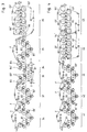
Die Fig. 1 bis 4 zeigen schematische Seitenansichten auf mehrere unterschiedliche Trockenpartien mit mehreren Ein-Filz-Trockengruppen und mit wenigstens einer nachfolgenden Zwei-Filz-Trockengruppe.1 to 4 show schematic side views of several different dryer sections with several one-felt dryer groups and with at least one subsequent two-felt dryer group.
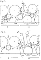
Die Fig. 5 bis 8 zeigen (gegenüber den Fig. 1 bis 4 vergrößerte) schematische Seitenansichten auf die Übergangszone zwischen einer Ein-Filz-Trockengruppe und einer nachfolgenden Zwei-Filz-Trockengruppe mit den dazugehörenden Bändel-Führungseinrichtungen.5 to 8 show (compared to FIGS. 1 to 4 enlarged) schematic side views of the transition zone between a one-felt drying group and a subsequent two-felt drying group with the associated ribbon guide devices.
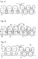
Die Fig. 9 bis 11 sind ähnlich den Fig. 5 bis 8 und zeigen unterschiedliche Höhenabstände der Zylinder- bzw. Umlenkwalzen-Achsen von einer Bezugsebene.FIGS. 9 to 11 are similar to FIGS. 5 to 8 and show different height distances of the cylinder or deflecting roller axes from a reference plane.
Die Fig. 12 und 13 zeigen weitere Ausführungsbeispiele in schematischer Seitenansicht.12 and 13 show further exemplary embodiments in a schematic side view.
Die Fig. 14 - 17' sind Diagramme, welche das optimale Verhältnis zwischen den Ein-Filz- und den Zwei-Filz-Bahnkontaktflächen für unterschiedliche Papiersorten darstellen.14-17 'are diagrams illustrating the optimal relationship between the one-felt and two-felt web contact areas for different types of paper.
Die Fig. 18A - 18D zeigen verschiedene Übergangsstellen zwischen einer unten befilzten Ein-Filz-Trockengruppe und einer nachfolgenden Zwei-Filz-Trockengruppe.18A-18D show different transition points between a felted single-felt dryer group below and a subsequent two-felt dryer group.
Die Fig. 19 und 20 sind schematische Seitenansichten auf weitere erfindungsgemäße Trockenpartien.19 and 20 are schematic side views of further dryer sections according to the invention.
Die in Fig. 1 dargestellte Trockenpartie hat zunächst sechs hintereinander angeordnete Ein-Filz-Trockengruppen 11-16. Jede dieser Trockengruppen hat einen einzigen endlosen Filz F. Beispielsweise in der ersten Trockengruppe 11 läuft der Filz F zusammen mit der Bahn 9 abwechselnd über Trockenzylinder 51 und über Umlenkwalzen 51', die vorzugsweise als Saugwalzen ausgebildet sind. In den ersten beiden Trockengruppen 11 und 12 sowie in der vierten und in der sechsten Trockengruppe 14, 16 kommt die Bahnunterseite mit den Zylindern in Kontakt. Dementsprechend liegen hier die Trockenzylinder 51, 52, 54, 56 oberhalb der dazugehörenden Umlenksaugwalzen 51', 52', 54' bzw. 56'; die Zylinder sind hier "oben befilzt". Anders dagegen in der dritten Trockengruppe 13 und in der fünften Trockengruppe 15: Hier kommen die Zylinder 53, 55 mit der Bahnoberseite in Kontakt; sie sind deshalb "unten befilzt" und liegen unterhalb der dazugehörenden Umlenksaugwalzen 53', 55'. Folglich sind die zwischen den Trockengruppen 12 bis 16 vorhandenen Trennstellen als sogenannte Wendetrennstellen ausgebildet. Bezüglich der Einzelheiten dieser Wendetrennstellen wird ausdrücklich auf die DE-A 4311351 (Akte P 4953 K) hingewiesen.The dryer section shown in FIG. 1 initially has six single-felt dryer groups 11-16 arranged one behind the other. Each of these dryer groups has a single endless felt F. For example, in the
Man sieht aus Fig. 1, daß an jeder dieser Wendetrennstellen die Papierbahn 9 einen kurzen offenen Zug bildet; d.h. sie ist vorübergehend nicht durch einen Filz gestützt. Sie läuft im Bereich einer kleinen Saugzone einer Transferwalze 58 auf den jeweils nächsten Filz auf. In Fig. 1 sind diese Transferwalzen 58 die einzigen Saugwalzen mit innenliegendem stationären Saugkasten. Die Umlenksaugwalzen 51' bis 56' sind dagegen frei von inneren stationären Einbauten und von direkten Sauganschlüssen. Stattdessen ist an jeder dieser Umlenksaugwalzen ein externer Saugkasten 59 vorgesehen. Dieser liegt in der zwischen zwei benachbarten Trockenzylindern befindlichen sogenannten Tasche und hat an der Stelle, wo Filz F und Bahn 9 gemeinsam den ersten dieser zwei Zylinder verlassen, eine Leiste 60 (siehe Fig. 7), welche die vom Filz herantransportierte Luftgrenzschicht abstreift und umlenkt.It can be seen from FIG. 1 that the
Auf die letzte Ein-Filz-Trockengruppe 16 folgt eine Zwei-Filz-Trockengruppe 17 mit einigen unteren Zylindern 57 und einigen oberen Zylindern 57', sowie mit einem Unterfilz UF mit einem Oberfilz OF. Hier läuft die Bahn 9 mäanderförmig abwechselnd über die unteren und oberen Zylinder. In Fig. 1 ist zwischen den letzten zwei Zylindern ein Spitzenschneider S angedeutet.The last one-felt
Die in Fig. 2 dargestellte Trockenpartie hat beispielsweise drei (oder vier oder fünf) Ein-Filz-Trockengruppen 21 - 23; diese sind jedoch, im Gegensatz zu Fig. 1, alle oben befilzt. Mit anderen Worten: Sämtliche Trockenzylinder 71 -73 berühren die Bahnunterseite. Ein weiterer Unterschied zu Fig. 1 besteht darin, daß die Umlenksaugwalzen 71' bis 73' interne stationäre Saugkästen haben und in nur geringem Abstand von den benachbarten Trockenzylindern angeordnet sind. Ferner sind nunmehr beispielsweise zwei (oder drei) Zwei-Filz-Trockengruppen 24, 25 mit unteren Zylindern 74, 75 und mit oberen Zylindern 74' und 75' vorgesehen.The dryer section shown in FIG. 2 has, for example, three (or four or five) single-felt dryer groups 21-23; however, in contrast to FIG. 1, these are all felted above. In other words: All drying cylinders 71-73 touch the underside of the web. Another difference from FIG. 1 is that the deflection suction rolls 71 'to 73' have internal stationary suction boxes and are arranged at a short distance from the adjacent drying cylinders. Furthermore, two (or three) two-felt
Während die Trockenpartien gemäß den Fig. 1 und 2 ausschließlich horizontale Zylinder-Reihen aufweisen, ist in den Fig. 3 und 4 folgendes vorgesehen: Zwecks Verkürzung der Gesamt-Baulänge der Trockenpartie sind die Zylinder der Ein-Filz-Trockengruppen, wie an sich aus der DE 4 041 493 bekannt, in mehreren gegen die vertikale Richtung geneigten Reihen angeordnet, wobei rückwärts und vorwärts geneigte Reihen abwechselnd aufeinanderfolgen. Gemäß Fig. 3 bilden zwei V-förmige Doppelreihen eine erste Trockengruppe 31 und eine zweite Trockengruppe 32. Die Zylinder 81, 82 dieser beiden Trockengruppen sind oben befilzt. Danach folgen zwei unten befilzte Trockengruppen 33, 34. Die beispielsweise drei (oder vier) Zylinder 83 der dritten Trockengruppe bilden eine rückwärts geneigte Reihe. Dagegen bilden die Zylinder 84 der vierten Trockengruppe eine vorwärts geneigte Reihe. Zwischen den untersten Zylindern dieser beiden Trockengruppen 33, 34 kann - zwecks Entfernung von Ausschußpapier nach unten - mittels einer schwenkbaren Filzleitwalze 87 ein Spalt geöffnet werden. Die fünfte Trockengruppe 35 hat wiederum ausschließlich oben befilzte Trockenzylinder 85, die wiederum eine V-förmige Doppelreihe bilden. Hinter dem letzten Zylinder dieser Trockengruppe 35 wird die Bahn schräg nach unten zum ersten unteren Zylinder 86 der nachfolgenden Zwei-Filz-Trockengruppe 36 geführt. Gemäß Fig. 4 sind ausschließlich oben befilzte und V-förmige Ein-Filz-Trockengruppen 41, 42 und 43 vorgesehen, gefolgt von zwei Zwei-Filz-Trockengruppen 44 und 45. In beiden Fig. 3 und 4 sind - abweichend von DE '493 - sämtliche Umlenksaugwalzen 81' bis 85' und 91' bis 93', die in der jeweiligen Trockengruppe zwischen zwei Zylindern angeordnet sind, in einem vergrößerten Abstand von diesen Zylindern angeordnet und mit externen Saugkästen ausgerüstet. Diese Bauweise ist nicht nur mit geringeren Kosten herstellbar; sie ist vielmehr auch energiesparend; denn zwischen je zwei Zylindern ist eine verlängerte freie Ausdampfstrecke vorhanden, so daß die Trocknung wirtschaftlicher ist. Die letzteren Gesichtspunkte gelten auch für die Anordnung gemäß Fig. 1.1 and 2 have only horizontal rows of cylinders, the following is provided in FIGS. 3 and 4: In order to shorten the overall length of the drying section, the cylinders of the single-felt drying groups are, as such, from known from DE 4 041 493, arranged in a plurality of rows inclined against the vertical direction, rows back and forth inclined alternating in succession. 3, two V-shaped double rows form a
In Fig. 5 erkennt man von der Trockenpartie gemäß Fig. 2 die letzten zwei Trockenzylinder 73 der letzten Ein-Filz-Trockengruppe 23 und die ersten drei Zylinder 74, 74' der Zwei-Filz-Trockengruppe 24. Ferner erkennt man eine mit innerem Saugkasten versehene Umlenksaugwalze 73' und (abweichend von Fig. 2) vor dem ersten unteren Trockenzylinder 74 eine Transfer-Saugwalze 58, ebenfalls mit einem stationären inneren Saugkasten. Eine automatische seillose Bändel-Führungseinrichtung ist in der Ein-Filz-Trockengruppe 23 beispielsweise dadurch gebildet, daß jede Umlenksaugwalze 73 an einem ihrer beiden Enden eine an sich bekannte Randsaugzone aufweist. Auch sind an einem Schaber-Tragkörper 76 Luftblaseinrichtungen vorgesehen, die symbolisch durch Pfeile dargestellt sind, außerdem eine Luftblasdüse 79. An der Stelle, wo die Bahn 9 und der Filz F gemeinsam vom letzten Zylinder 73 ablaufen, kann ein (nur im Bereich des Bändels wirksamer) Randsaugkasten R, Bahnstabilisator oder dergleichen angeordnet sein. Oder am letzten Zylinder 73 wird ein kurzer, nur den Bändel-Bereich überdeckender "Bändel-Leitschaber" 88 vorgesehen, der ebenfalls eine Luftblasdüse haben kann (z.B. DE-GM 8 914 679).5, the last two drying
Auch in der Zwei-Filz-Trockengruppe 24 ist eine automatische seillose Bändel-Führungseinrichtung vorgesehen, die folgendermaßen ausgebildet ist: Entlang der von unten nach oben zum Zylinder 74' verlaufenden freien Bahn-Laufstrecke verläuft einerseits eine Wand eines Schaber-Tragkörpers 77 und andererseits eine Führungsplatte 78, z.B. gemäß DE-GM 9 109 313. Jedes dieser Elemente hat Blasluft-Öffnungen, um einen Blasluftstrahl in wesentlichen in Bahnlaufrichtung auszustoßen. Oberhalb des ersten unteren Zylinders 74 laufen die zwei Filze F und OF in einem kleinen Abstand a parallel zueinander (a = ca. 30-50 mm). Dadurch wird vermieden, daß der Oberfilz OF große Luftmengen in die Tasche T transportiert, die seitlich nach außen entweichen und den ankommenden Bändel nach außen treiben würden. Die dargestellte Anordnung gewährleistet, daß der ankommende Bändel sicher vom ersten Zylinder 74' erfaßt und weitergeleitet wird; sie ist auch an der Trennstelle zwischen zwei Zwei-Filz-Trockengruppen (z.B. 24, 25, Fig.2) anwendbar, sowohl an den Oberfilzen als auch an den Unterfilzen.Also in the two-felt
Anstelle der oben beschriebenen Luftblaselemente 77,78 können zum Einfädeln des Bändels auch Einrichtungen, welche Unterdruck erzeugen, angewandt werden. Hierzu kommen beispielsweise die Einrichtungen gemäß US PS 4,022,366 in Betracht. Nach erfolgreichem Bändel-Einfädeln kann eine solche Einrichtung in den Bereich außerhalb der Trockenpartie ausgeschwenkt werden. Bei einer anderen möglichen Ausführungsform der Erfindung wird wenigstens eine der Filzleitwalzen als Saugwalze ausgebildet und derart angeordnet, daß sie die Bahn von einem anderen Filz abnehmen kann, ähnlich der Methode, die in US PS 4,485,567 offenbart ist.Instead of the
Falls erforderlich kann während des Bändel-Einziehvorganges zunächst folgendes vorgesehen werden: In der zwischen den beiden letzten Zylindern 73 vorgesehenen Umlenksaugwalze 73' wird der Unterdruck vorübergehend abgeschaltet; außerdem wird die Luftblasdüse 79 ausgeschaltet, so daß der Bändel, wie bei 9A dargestellt zunächst nach unten in den Keller läuft. Wenn dann der Bändel stabil durch die vorangehenden Ein-Filz-Trockengruppen läuft, wird mittels der Blasdüse 79 und eines Messers 80 eine neue Bändelspitze 9B gebildet und diese an die wieder mit Unterdruck beaufschlagte Umlenksaugwalze 73' geführt. Folglich läuft nunmehr der Bändel hinüber zur Zwei-Filz-Trockengruppe 25 und durch diese hindurch bis zum Schluß der Trockenpartie. Eine solche Einrichtung ist auch in Fig. 7 vorhanden.If necessary, the following can first be provided during the ribbon pulling-in process: in the deflection suction roll 73 'provided between the last two
Gemäß Fig. 6 ist zwischen dem letzten Zylinder 73 der Ein-Filz-Trockengruppe 23 und dem ersten unteren Zylinder 74 der Zwei-Filz-Trockengruppe 24 folgendes vorgesehen: Eine Leitwalze 18 des Filzes F und eine Leitwalze 19 des Unterfilzes UF sind derart angeordnet, daß sich die Filze einander überlappen. Während des normalen Betriebes ist zwischen den Filzen F und UF ein gewisser Abstand vorhanden, so daß die Bahn 9 frei, also ohne Stützung durch den Filz F, vom Zylinder 73 zur Filzleitwalze 19 läuft. Während des Bändel-Einziehens kann die Leitwalze 18 in die mit strichpunktierten Linien dargestellte Position gebracht werden, so daß sich die Filze F und UF vorübergehend einander berühren oder nahezu berühren. Ein Bändel-Leitschaber 88 kann zusätzlich vorgesehen werden.According to FIG. 6, the following is provided between the
In den Fig. 7 und 8 ist der erste Zylinder 94' der Zwei-Filz-Trockengruppe ein oberer Zylinder. Deswegen ist zwischen diesem und dem letzten Zylinder 93 der Ein-Filz-Trockengruppe eine Umlenksaugwalze 96 vorgesehen. Diese kann gemäß Fig. 7 in der Schlaufe des Filzes F der Ein-Filz-Trockengruppe liegen, wobei der Filz F den oberen Zylinder 94' tangiert und die Bahn 9 an diesen abgibt. Gemäß Fig. 8 kann die Umlenksaugwalze 96' im Oberfilz OF der Zwei-Filz-Trockengruppe liegen. Dieser Filz tangiert den letzten Zylinder 93 der Ein-Filz-Trockengruppe und nimmt die Bahn von diesem ab. Deutlich erkennbar in den Fig. 7 und 8 ist wiederum eine automatische seillose Bändel-Führungseinrichtung, in Form von Bändel-Leitschabern 88 und in Form von (durch Pfeile symbolisch dargestellten) Blasdüsen, die an Schabertragkörpern 77 oder an einem separaten Blasrohr 87 angeordnet sind. Damit der in Richtung zum ersten oberen Zylinder 94' laufende Unterfilz UF nicht unnötig Luft in die Tasche T fördert, kann eine zusätzliche Filzleitwalze 100 (oder ein Luftschaber) vorgesehen werden.7 and 8, the first cylinder 94 'of the two-felt dryer group is an upper cylinder. Therefore, a
In Fig. 9 ist - verglichen mit Fig. 1 - ein vergrößerter Abstand H zwischen den Ebenen E1 und E2 vorgesehen, wodurch der Bahn 9 zwischen je zwei Zylindern der Ein-Filz-Trockengruppe eine vergrößerte Ausdampfstrecke zur Verfügung steht. In E1 liegen die Zylinder-Achsen, in E2 dagegen die Achsen der Umlenksaugwalzen und wenigstens angenähert die Achsen der unteren Zylinder der Zwei-Filz-Trockengruppe.In FIG. 9, compared to FIG. 1, an increased distance H is provided between the planes E1 and E2, as a result of which the
Gemäß Fig. 10 ist - abweichend von den Fig. 1 und 2 - folgendes vorgesehen: Die Achsen der Zylinder der Ein-Filz-Trockengruppe liegen in derselben horizontalen Ebene E1 wie die Achsen der oberen Zylinder der Zwei-Filz-Trockengruppe. Somit können für alle diese Zylinder einheitliche Ständer 89 vorgesehen werden. Ferner liegen hierdurch die Achsen der Zylinder der Ein-Filz-Trockengruppe in einem größeren Höhenabstand HO über einer Bezugsebene E0 als beispielsweise die Achsen der Zylinder 56 in Fig. 1. Daraus folgt, daß man auch den Höhenabstand H zwischen den Umlenksaugwalzen und den Zylindern sehr große wählen kann, falls - verglichen mit Fig. 9 - noch weiter vergrößerte Ausdampfstrecken zwischen den Zylindern erforderlich sind. Dabei können die Achsen der (strichpunktiert angedeuteten) Umlenksaugwalzen wiederum wenigstens angenähert in derselben horizontalen Ebene E2 liegen wie die Achsen der unteren Zylinder der Zwei-Filz-Trockengruppe. Die beschriebenen Vorteile können noch verstärkt angewandt werden, wenn gemäß Fig. 11 die Achsen der Zylinder der Ein-Filz-Trockengruppe (Ebene E1) oberhalb der Achsen der oberen Zylinder der Zwei-Filz-Trockengruppen (Ebene E3) angeordnet werden.According to FIG. 10, the following is provided - in deviation from FIGS. 1 and 2: The axes of the cylinders of the one-felt drying group lie in the same horizontal plane E1 as the axes of the upper cylinders of the two-felt drying group. Uniform stands 89 can thus be provided for all these cylinders. Furthermore, this means that the axes of the cylinders of the single-felt dryer group are at a greater height distance HO above a reference plane E0 than, for example, the axes of the
Die Fig. 12 zeigt eine Alternative zu Fig. 1. Die Zwei-Filz-Trockengruppe 17A ist gemäß DE-PS 3 623 971 (Akte P 4243) folgendermaßen ausgebildet: Die papierbahn 9 läuft zunächst über einen unteren Zylinder 61, dann nacheinander über zwei obere Zylinder 62, dann nacheinander über zwei untere Zylinder 63, dann nacheinander über zwei obere Zylinder 64, dann nacheinander über zwei untere Zylinder 65 und schließlich über einen oberen Zylinder 66.FIG. 12 shows an alternative to FIG. 1. The two-felt dryer group 17A is designed as follows according to DE-PS 3 623 971 (file P 4243): the
Zwischen den Zylindern jedes Zylinder-Paares 62-65 ist eine Umlenksaugwalze 62'-65' angeordnet. Dadurch ist die Anzahl der freien Papierbahn-Züge zwischen den zwei horizontalen Zylinder-Reihen etwa halbiert. Das Bändel-Einziehen kann genauso wie oben anhand der Fig. 5 und 7 erläutert automatisch, also ohne Seile stattfinden. Eventuell anfallendes Ausschuß-Papier wird selbsttätig zum hinteren Ende der Trockengruppe 17A transportiert und dort ausgestoßen.A deflection suction roller 62'-65 'is arranged between the cylinders of each pair of cylinders 62-65. As a result, the number of free paper web trains between the two horizontal rows of cylinders is approximately halved. The ribbon pulling can take place automatically, that is to say without ropes, just as explained above with reference to FIGS. Any scrap paper that occurs is automatically transported to the rear end of the drying group 17A and ejected there.
Die Fig. 13 zeigt, daß man auch eine unten befilzte Ein-Filz-Trockengruppe 15A unmittelbar vor einer Zwei-Filz-Trockengruppe 16A anordnen kann. Gemäß einer anderen Alternative hat in der Zwei-Filz-Trockengruppe 16A jeder untere Zylinder 67, 68 seinen eigenen Filz FA,FB, um das Abführen von Ausschuß zu erleichtern.Fig. 13 shows that a one-felt
Abweichend von den Fig. 1 - 13 kann zwischen der letzten Ein-Filz-Trockengruppe und der ersten Zwei-Filz-Trockengruppe ein Zusatz-Aggregat, z.B. eine Leimpresse, ein Feuchtglättwerk oder dgl., angeordnet werden.Deviating from Figs. 1-13, an additional unit, e.g., between the last one-felt drying group and the first two-felt drying group, can be used. a size press, a dampening unit or the like can be arranged.
Gemäß Fig. 18A liegen die Drehachsen der Zylinder 200 der unten befilzten Ein-Filz-Trockengruppe in einer horizontalen Ebene II und die Drehachsen der dazugehörenden Umlenksaugwalzen in einer Ebene III. Die beiden Ebenen II und III sind zwischen den Ebenen IV und V angeordnet, in denen die Drehachsen der oberen bzw. der unteren Zylinder der nachfolgenden Zwei-Filz-Trockengruppe angeordnet sind. Die Papierbahn 208 läuft vom letzten Zylinder 200 der Ein-Filz-Trockengruppe zum ersten oberen Zylinder 202 der Zwei-Filz-Trockengruppe auf einem ungefähr senkrechten Laufweg von unten nach oben. Die hier befindlichen Filzleitwalzen 204 und 206 liegen nahe beieinander, so daß eine nur kurze freie Bahnlaufstrecke vorhanden ist. Die Durchmesser der Zylinder der Zwei-Filz-Trockengruppe sind etwas kleiner als die Durchmesser der Zylinder der Ein-Filz-Trockengruppe. Daraus ergeben sich verschiedene Vorteile:
Man hat vom Papiermaschinenboden I aus leichten Einblick in die Taschen, die sich zwischen den oberen und unteren Zylindern der Zwei-Filz-Trockengruppe befinden. Man kann auch, falls erwünscht, den Höhenabstand zwischen den Ebenen IV und V relativ klein wählen, um die Länge der freien Bahnzüge zwischen den Zylindern zu verringern. Daraus resultiert auch ein relativ geringer Höhenabstand der Ebene IV vom Papiermaschinenboden I, so daß die oberen Zylinder 202 leicht zugänglich und bedienbar sind.According to FIG. 18A, the axes of rotation of the
From paper machine floor I you can easily see the pockets that are located between the upper and lower cylinders of the two-felt dryer group. If desired, the height distance between planes IV and V can also be chosen to be relatively small in order to reduce the length of the free web trains between the cylinders. This also results in a relatively small height distance of plane IV from paper machine base I, so that
Gemäß Fig. 18B kommt der untere Filz 220 der Zwei-Filz-Trockengruppe in einen ungefähr tangentialen Kontakt mit dem letzten Zylinder 200 der wiederum unten befilzten Ein-Filz-Trockengruppe. Dies ist eine sog. Lick-up-Bahnüberführung. An der Stelle LU übernimmt der Filz 220 die Papierbahn vom Zylinder 200 und führt sie über eine Saugleitwalze 210 zum ersten untenliegenden Zylinder 212 der Zwei-Filz-Trockengruppe. Beim Einfädeln des Bändels wird mittels einer Luftdüse 216 (oder mittels einer ähnlichen Einrichtung) ein Luftstrahl gegen den Mantel des Zylinders 200 gerichtet. Hierdurch wird sichergestellt, daß die Spitze des Bändels mit dem unteren Filz 220 weiterläuft. Die Luftdüse 216 kann an einem Arm befestigt sein, der mittels einer Schwenkeinrichtung 218 nach außen geschwenkt werden kann, so daß bei Anfall von Papierausschuß das Entfernen des Ausschusses von der Oberseite des Zylinders 200 nicht behindert wird.18B, the lower felt 220 of the two-felt drying group comes into roughly tangential contact with the
Die Fig. 18C unterscheidet sich nur geringfügig von der Fig. 18A. Die Papierbahn läuft wieder zusammen mit dem Filz der unten befilten Ein-Filz-Trockengruppe bis zu einer Filzleitwalze 224 und von hier frei zu einer Saugfilzleitwalze 222. Diese hat eine relativ kleine Unterdruckzone 228, die dafür sorgt, daß die Papierbahn 226 sicher mit dem oberen Filz 230 der Zwei-Filz-Trockengruppe weiterläuft.FIG. 18C differs only slightly from FIG. 18A. The paper web again runs together with the felt of the one-felt dryer group, which is filmed below, to a felt
Die Anordnung der Trockenzylinder der Fig. 18D entspricht derjenigen der Fig. 18B. Ein Unterschied besteht aber darin, daß der Filz der Ein-Filz-Trockengruppe vom letzten Zylinder 200 zusammen mit der Papierbahn über eine Umlenksaugwalze 232 läuft und die Papierbahn danach an den ersten unteren Zylinder 212 der Zwei-Filz-Trockengruppe übergibt. Hierzu berührt der genannte Filz den Zylinder 212 im wesentlichen tangential.The arrangement of the drying cylinders in FIG. 18D corresponds to that in FIG. 18B. One difference, however, is that the felt of the one-felt dryer group runs from the
Die Fig. 19 zeigt eine Trockenpartie, in der die Papierbahn 9 zuerst durch zwei (oder drei) oben befilzte Ein-Filz-Trockengruppen 240 und 241 läuft. Auf diese folgt eine unten befilzte Ein-Filz-Trockengruppe 242 und danach wieder eine oben befilzte Ein-Filz-Trockengruppe 244. An diese schließen sich zwei Zwei-Filz-Trockengruppen 246 und 247 an. Eine Besonderheit dieser Anordnung ist, daß die Zylinder sämtlicher oben befilzten Ein-Filz-Trockengruppen wenigstens angenähert in der gleichen Ebene liegen wie die oberen Zylinder der Zwei-Filz-Trockengruppe. In ähnlicher Weise liegen die Drehachsen der Zylinder der unten befilzten Ein-Filz-Trockengruppe 242 wenigstens angenähert in der gleichen Ebene wie die Achsen der unteren Zylinder 74, 75 der Zwei-Filz-Trockengruppen 246 und 247.19 shows a dryer section in which the
Es wurde oben schon angedeutet, daß gemäß der Erfindung die Optimierung des Verhältnisses der Trockenkapazitäten der Ein-Filz- und der Zwei-Filz-Trockengruppen in einer gemischten Trockenpartie wesentliche Auswirkungen hat auf die erzielbaren Eigenschaften des fertigen Papieres, auf die Produktionskosten und auf die Betriebsbedingungen der Trockenpartie. Es wurde erkannt, daß die optimale Position der "Grenze" zwischen den Ein-Filz- und den Zwei-Filz-Trockengruppen für die unterschiedlichen Papiersorten bestimmt werden muß, wobei der Prozentsatz der Bahn-Kontaktfläche der Trockenzylinder der Ein-Filz-Trockengruppe relativ zur Bahn-Kontakfläche der gesamten Trockenpartie ermittelt werden muß. Einige Resultate sind in den Fig. 14 - 17' dargestellt. Diese Resultate hängen von mehreren Faktoren ab, hauptsächlich jedoch von der Papiersorte; sie wurden bestimmt für die angegebenen Geschwindigkeitsbereiche; sie dürften jedoch auch für darüberliegende Geschwindigkeiten, zumindest bis zur Geschwindigkeit 2000 m/min, Gültigkeit haben.It has already been indicated above that according to the invention the optimization of the ratio of the drying capacities of the one-felt and the two-felt dryer groups in a mixed dryer section has a significant effect on the achievable Properties of the finished paper, the production costs and the operating conditions of the dryer section. It has been recognized that the optimal position of the "boundary" between the one-felt and two-felt dryer groups must be determined for the different types of paper, with the percentage of web contact area of the dryer cylinders of the one-felt dryer group relative to Path contact area of the entire dryer section must be determined. Some results are shown in Figures 14-17 '. These results depend on several factors, but mainly on the type of paper; they were determined for the specified speed ranges; however, they should also be valid for higher speeds, at least up to a speed of 2000 m / min.
Die Fig. 14 zeigt für Zeitungsdruckpapiere mit einem Flächengewicht zwischen 35 und 56 g/m², hergestellt mit einer Arbeitsgeschwindigkeit zwischen 1300 und 1600 m/min, folgendes: Von der Bahn-Kontaktfläche der gesamten Trockenpartie sollen 41 - 61 % in den Ein-Filz-Trockengruppen zur Verfügung gestellt werden. Die optimale "Grenze", d.h. der optimale Übergangspunkt, liegt beim Wert 50 %, wobei der bis dahin erreichte Trockengehalt der Papierbahn 50 - 55 % beträgt.14 shows the following for newsprint paper with a basis weight between 35 and 56 g / m 2, produced at a working speed between 1300 and 1600 m / min: 41-61% of the web contact area of the entire dryer section should go into the single felt - Dry groups are made available. The optimal "limit", i.e. the optimal transition point is 50%, whereby the dry content of the paper web reached by then is 50-55%.
Die Resultate für andere Papiersorten sind in den weiteren Fig. 15 - 17' dargestellt. Die Fig. 15 gilt für holzfreie Papiere mit Flächengewichten zwischen 40 und 120 g/m². Die optimale "Grenze" liegt dort, wo die Papierbahn etwa über 54 % der Bahn-Kontaktfläche der gesamten Trockenpartie gelaufen ist. Der günstige Bereich liegt zwischen 44 und 64 %. Die entsprechenden Werte für SC-Papiere (Papiere, die in einem Superkalander geglättet werden) sind aus Fig. 16 ersichtlich. Die Fig. 17 zeigt die Resultate für LWC-Papiere; dies sind dünne gestrichene Papiere mit einem Flächengewicht zwischen 30 und 50 g/m². Schließlich zeigt die Fig. 17', daß Kopierpapier mit ungefähr 75 g/m² an einer Stelle von der Ein-Filz- in die Zwei-Filz-Trockengruppe überführt werden sollte, nachdem es 45 - 65 % der Bahn-Kontaktfläche der gesamten Trockenpartie durchlaufen hat. Die optimale "Grenze" liegt bei 55 %.The results for other types of paper are shown in further FIGS. 15-17 '. Fig. 15 applies to wood-free papers with basis weights between 40 and 120 g / m². The optimal "limit" is where the paper web has run about 54% of the web contact area of the entire dryer section. The favorable range is between 44 and 64%. The corresponding values for SC papers (papers which are smoothed in a supercalender) can be seen from FIG. 16. Figure 17 shows the results for LWC papers; these are thin coated papers with a basis weight between 30 and 50 g / m². Finally, Figure 17 'shows that approximately 75 g / m² copy paper should be transferred from the one-felt to the two-felt dryer group at one point after passing 45-65% of the web contact area of the entire dryer section Has. The optimal "limit" is 55%.
Zusammenfassend werden die genannten Daten in der nachfolgenden Tabelle dargestellt.
In Fig. 20 wird ein weiterer Aspekt der Erfindung dargestellt. Die Konfiguration ist ähnlich derjenigen der Fig. 5. Man erkennt die letzten zwei Trockenzylinder 73 der letzten Ein-Filz-Trockengruppe 23 mit einem oberen Filz F. Ausßerdem sieht man die ersten 6 Zylinder 74, 74' der ersten Zwei-Filz-Trockengruppe 24, mit einem oberen Filz OF und mit einem unteren Filz UF, ferner mit oberen Filzleitwalzen 199 und mit unteren Filzleitwalzen 198. Jede dieser Filzleitwalzen liegt zwischen zwei benachbarten Trockenzylindern.Another aspect of the invention is illustrated in FIG. The configuration is similar to that of FIG. 5. The last two drying
Entweder die oberen Filzleitwalzen 199 oder die unteren Filzleitwalzen 198 sind als Saugwalzen ausgebildet (in einer weiteren möglichen Ausführungsform könnten auch sämtliche Filzleitwalzen 198 und 199 als Saugwalzen ausgebildet sein). Im dargestellten Ausführungsbeispiel sind nur die unteren Filzleitwalzen 198 Saugwalzen und deshalb über ein Leitungssystem 197, mit Steuerventil 196 an ein Sauggebläse 195 angeschlossen. Im Betrieb entfernen die unteren Saugfilzleitwalzen 198 feuchte Luft aus jeder zweiten Tasche 194. Dies sind diejenigen Taschen, die sich unmittelbar unter den oberen Zylindern 74' befinden und die deshalb mit der unteren Seite der Papierbahn in Berührung kommen. Deshalb wird hierdurch das Ausdampfen der unteren Bahnseite verbessert relativ zum Ausdampfen der oberen Bahnseite. Diese Methode ist dazu geeignet, um einer etwaigen Roll-Neigung des fertigen Papieres entgegenzuwirken. Eine solche Roll-Neigung kann verursacht werden durch die Ein-Filz-Trockengruppen oder andere Faktoren. Genauer gesagt, das verbesserte Ausdampfen der Bahn-Unterseite wirkt einer nach oben gerichteten Roll-Neigung entgegen.Either the upper felt guide rolls 199 or the lower felt guide rolls 198 are designed as suction rolls (in a further possible embodiment, all of the felt guide rolls 198 and 199 could also be designed as suction rolls). In the exemplary embodiment shown, only the lower
Wenn dementsprechend eine nach unten gerichtete Roll-Neigung des fertigen Papiers auftritt, dann sollte für ein zusätzliches Abführen von Feuchtigkeit aus den anderen Taschen 193 gesorgt werden. Die Taschen 193 liegen unmittelbar oberhalb der unteren Zylinder 74. Zu diesem Zweck sollten die oberen Filzleitwalzen 199 als Saugleitwalzen ausgebildet sein, entgegen der Darstellung gem. Fig. 20. Wenn es nicht vorhersehbar ist, ob eine nach oben oder eine nach unten gerichtete Roll-Neigung im fertigen Papier vorhanden sein wird, dann sollten sämtliche Filzleitwalzen 198 und 199 Saugwalzen sein. In diesem Fall sollten die unteren Saugfilzleitwalzen 198 durch das in Fig. 20 dargestellte Ventil 196 gesteuert werden, während die oberen Saugfilzleitwalzen 199 über eine separate, nicht dargestellte Saugleitung (mit einem zusätzlichen Steuerventil) besaugt werden sollten. Es wäre in diesem Fall möglich, das Ausdampfen entweder der Oberseite oder der Unterseite der Papierbahn 9 zu verstärken, je nachdem, ob eine nach oben oder nach unten gerichtete Roll-Neigung des fertigen Papiers besteht.Accordingly, if there is a downward tendency to roll of the finished paper, then additional wicking of moisture from the
Anstatt mit Hilfe von Saugfilzleitwalzen gibt es auch andere Möglichkeiten, die Intensität der Ausdampfung der beiden Bahnseiten zu steuern. Wenn z.B. die Trockenzylinder mit Schabern ausgerüstet sind (siehe Fig. 5), dann kann man feuchte Luft durch die hohlen Schaberbalken absaugen. Eine andere Möglichkeit besteht darin, trockene Luft entweder in die Taschen 194 oder in die Taschen 193 einzublasen. Zu diesem Zweck können Luftblaseinrichtungen (nicht dargestellt) unterhalb der unteren Filzleitwalzen 198 und/oder oberhalb der oberen Filzleitwalzen 199 angeordnet werden. Solche Luftblaseinrichtungen blasen trockene Luft durch den Unterfilz UF und/oder durch den Oberfilze OF in die betreffenden Taschen 193 und/oder 194. Solche Blaseinrichtungen sind dem einschlägigen Fachmann bekannt.Instead of using suction felt guide rollers, there are other options for controlling the intensity of the evaporation on both sides of the web. If e.g. the drying cylinders are equipped with scrapers (see Fig. 5), then moist air can be extracted through the hollow scraper bars. Another option is to blow dry air into either
Die unteren Saugfilzleitwalzen 198, dargestellt in Fig. 20, bieten einen weiteren Vorteil:
Wenn während des Betriebes die Papierbahn 9 abreißt, dann wird das Ausschußpapier automatisch weitertransportiert, und zwar mit Hilfe des durch die unteren Saugfilzleitwalzen 198 erzeugten Unterdruckes. Das Ausschußpapier läuft dann selbsttätig vom einen unteren Zylinder 74 zum nächsten bis es das Ende der Zwei-Filz-Trockengruppe 24 erreicht. Sofern auch die oberen Filzleitwalzen 199 als Saugwalzen ausgebildet sind, sollte deren Saugleitung bei einem Abriß der Papierbahn unverzüglich geschlossen werden.The lower suction felt guide rolls 198, shown in FIG. 20, offer a further advantage:
If the
Die Saugleitwalzen 198 haben, wie üblich, einen perforierten Walzenmantel und einen stationären innenliegenden Saugkasten, der eine Saugzone 190 begrenzt, wie in Fig. 20 schematisch dargestellt ist. Man beachte, daß die Saugzone 190 stets zur benachbarten Tasche 194 offen ist und daß ein gewisser Abstand d vorgesehen ist zwischen dem normalen Laufweg der Papierbahn 9 und dem Beginn der Saugzone 190. Dies ist vorgesehen wegen der unsymmetrischen Anordnung der Saugleitwalzen 198 zwischen den Zylindern 74 derart, daß die nach oben laufende Papierbahn 9 die Saugleitwalzen 198 tangiert. Die oben beschriebenen Vorteile können aber auch erzielt werden, wenn die Saugleitwalzen 198 symmetrisch zwischen benachbarten Zylindern 74 angeordnet sind, beispielsweise gemäß Fig. 11.As usual, the suction guide rolls 198 have a perforated roll shell and a stationary inner suction box which delimits a
Claims (30)
dadurch gekennzeichnet, daß das Einfädeln des Bändels in die Zwei-Filz-Trockengruppe (17) ebenfalls mittels einer automatischen seillosen Bändel-Führungseinrichtung (77, 78) erfolgt.Method for pulling a band (ie a temporarily formed edge strip of a running web) into a drying section serving to dry the web, which in successive drying groups (11-17) comprises a plurality of heatable drying cylinders (51-57 which come into contact with the web (9) '), the ribbon first being guided by means of an automatic rope-less ribbon guide device (79, 79') through at least one one-felt drying group (11-16), after which the ribbon is passed through at least one two-felt drying group ( 17) passes through,
characterized in that the threading of the band into the two-felt dryer group (17) also takes place by means of an automatic rope-less band guide device (77, 78).
Applications Claiming Priority (4)
| Application Number | Priority Date | Filing Date | Title |
|---|---|---|---|
| US10276693A | 1993-08-06 | 1993-08-06 | |
| US102766 | 1993-08-06 | ||
| US08/151,255 US5600897A (en) | 1993-08-06 | 1993-11-12 | Mixed dryer section including single-tier and double-tier drying groups with automatic ropeless threading |
| US151255 | 1993-11-12 |
Publications (3)
| Publication Number | Publication Date |
|---|---|
| EP0639668A2 true EP0639668A2 (en) | 1995-02-22 |
| EP0639668A3 EP0639668A3 (en) | 1996-02-07 |
| EP0639668B1 EP0639668B1 (en) | 2000-06-14 |
Family
ID=26799704
Family Applications (1)
| Application Number | Title | Priority Date | Filing Date |
|---|---|---|---|
| EP94111918A Expired - Lifetime EP0639668B1 (en) | 1993-08-06 | 1994-07-30 | Drying section |
Country Status (8)
| Country | Link |
|---|---|
| US (2) | US5600897A (en) |
| EP (1) | EP0639668B1 (en) |
| JP (1) | JPH07173788A (en) |
| AT (1) | ATE193914T1 (en) |
| BR (1) | BR9402704A (en) |
| CA (1) | CA2129723A1 (en) |
| DE (1) | DE59409398D1 (en) |
| FI (1) | FI121389B (en) |
Cited By (4)
| Publication number | Priority date | Publication date | Assignee | Title |
|---|---|---|---|---|
| EP0692569A3 (en) * | 1994-07-13 | 1998-01-07 | Andritz-Patentverwaltungs-Gesellschaft m.b.H. | Process and apparatus in a cylinder dryer of a papermaking machine with two dryer fabrics |
| EP0887462A2 (en) * | 1997-06-25 | 1998-12-30 | Voith Sulzer Papiermaschinen GmbH | Machine to manufacture a material web |
| WO2012084380A1 (en) * | 2010-12-23 | 2012-06-28 | Voith Patent Gmbh | Device for producing and/or treating material webs |
| AT506989B1 (en) * | 2008-06-02 | 2012-12-15 | Metso Paper Inc | METHOD AND APPARATUS FOR CARRYING OUT A SEILED TRAIN INTRODUCTION |
Families Citing this family (30)
| Publication number | Priority date | Publication date | Assignee | Title |
|---|---|---|---|---|
| DE59609272D1 (en) * | 1995-02-09 | 2002-07-11 | Voith Paper Patent Gmbh | Method for transferring a paper strip from a first to a second processing station in a paper machine |
| DE19548303B4 (en) * | 1995-12-22 | 2006-08-31 | Voith Paper Patent Gmbh | drying section |
| US5873180A (en) * | 1996-09-25 | 1999-02-23 | Beloit Technologies, Inc. | Papermaking dryer section with partitioned vacuum box for threading |
| US5762759A (en) * | 1997-01-27 | 1998-06-09 | Beloit Technologies, Inc. | Tail threading system for a papermaking machine |
| US6192597B1 (en) | 1997-04-17 | 2001-02-27 | Voith Sulzer Papiermaschinen Gmbh | Device for treating a fibrous pulp web as well as a sealing device for a device of this kind |
| FI102197B (en) * | 1997-05-27 | 1998-10-30 | Valmet Corp | Method and apparatus for head export of paper web |
| DE19724123A1 (en) | 1997-06-09 | 1998-12-10 | Voith Sulzer Papiermasch Gmbh | Device and method for transferring a threading strip or a material web |
| US5933979A (en) * | 1997-10-31 | 1999-08-10 | Beloit Technologies, Inc. | Restraint dryer for the drying end of a papermaking machine and a method thereof |
| DE19982816C2 (en) * | 1998-01-30 | 2002-08-29 | Metso Paper Inc | System and method for feeding the wet narrow piece of web from the first batch of a fabric machine to the second batch |
| DE19929927A1 (en) * | 1999-06-29 | 2001-01-04 | Voith Paper Patent Gmbh | Device for separating and transferring an insertion strip |
| DE10016492A1 (en) * | 2000-04-01 | 2001-10-11 | Voith Paper Patent Gmbh | Laxative |
| US6513263B2 (en) | 2000-10-06 | 2003-02-04 | Enerquin Air Inc. | Ventilator for offset pocket and method of ventilating the same |
| FI111174B (en) * | 2000-10-27 | 2003-06-13 | Metso Paper Inc | Method and apparatus for the tip drawing in a paper machine or corresponding drying portion |
| FI120005B (en) * | 2001-03-06 | 2009-05-29 | Metso Paper Inc | Arrangement with drying section of paper machine |
| DE10217571A1 (en) * | 2002-04-19 | 2003-11-06 | Voith Paper Patent Gmbh | drying section |
| JP3723158B2 (en) * | 2002-05-30 | 2005-12-07 | 三菱重工業株式会社 | Dryer vacuum box |
| DE10226629A1 (en) * | 2002-06-14 | 2003-12-24 | Voith Paper Patent Gmbh | Device for treating a fibrous web |
| FI121715B (en) * | 2002-07-01 | 2011-03-15 | Metso Paper Inc | Method and apparatus for threading a web in a drying section of a papermaking machine or the like |
| FI115310B (en) | 2002-12-20 | 2005-04-15 | Metso Paper Inc | Creator for a paper or cardboard machine |
| US7987614B2 (en) * | 2004-04-12 | 2011-08-02 | Erickson Robert W | Restraining device for reducing warp in lumber during drying |
| DE102004046795A1 (en) * | 2004-09-27 | 2006-04-06 | Voith Paper Patent Gmbh | Device and method for monitoring the transfer of a material web and especially the broadening of the width of a transfer strip on a demolition of the transfer strip or the material web |
| US8176650B2 (en) * | 2005-12-13 | 2012-05-15 | Kimberly-Clark Worldwide, Inc. | Method for warming up or cooling down a through-air dryer |
| DE102008000133A1 (en) * | 2008-01-23 | 2009-07-30 | Voith Patent Gmbh | drying section |
| AT506408B1 (en) * | 2008-06-17 | 2009-09-15 | Andritz Ag Maschf | DEVICE AND METHOD FOR TRANSFERRING A MATERIAL TRACK |
| AT506407B1 (en) * | 2008-06-17 | 2009-09-15 | Andritz Ag Maschf | DEVICE AND METHOD FOR TRANSFERRING A MATERIAL TRACK |
| AT506409B1 (en) * | 2008-06-17 | 2009-09-15 | Andritz Ag Maschf | DEVICE AND METHOD FOR TRANSFERRING A MATERIAL TRACK |
| FI124037B (en) * | 2008-09-03 | 2014-02-14 | Ev Group Oy | Apparatus as well as a method for improving the removal of paper from a drying machine of a papermaking machine |
| DE102009022871A1 (en) | 2009-05-27 | 2010-12-02 | Metso Paper, Inc. | Method for wireless feeding of web into single-wire extension of dryer section of e.g. paper machine, involves guiding insertion web from preceding drying cylinder to next drying cylinder, and detaching insertion web from preceding cylinder |
| CN104452416B (en) * | 2014-10-24 | 2016-03-30 | 徐州工业职业技术学院 | A kind of paper machine intelligence paper injection equipment |
| CN116753717B (en) * | 2023-08-17 | 2023-10-20 | 常州江河干燥设备有限公司 | Drying system and drying method |
Citations (6)
| Publication number | Priority date | Publication date | Assignee | Title |
|---|---|---|---|---|
| WO1990012151A1 (en) * | 1989-04-01 | 1990-10-18 | J.M. Voith Gmbh | Single-screen drying installation |
| US4967489A (en) * | 1988-12-14 | 1990-11-06 | Valmet Paper Machinery Inc. | Multi-cylinder dryer with twin-wire draw and web transfer between the cylinder groups |
| DE9110134U1 (en) * | 1991-08-16 | 1991-09-26 | J.M. Voith Gmbh, 7920 Heidenheim, De | |
| EP0472513A1 (en) * | 1990-08-21 | 1992-02-26 | Andritz-Patentverwaltungs-Gesellschaft m.b.H. | Procedure and device in a cylinder drying section of a paper machine |
| DE4328554A1 (en) * | 1993-08-25 | 1994-03-31 | Voith Gmbh J M | Paper-making machine drying section - has automatic leader guide system also at the start of twin-blanket drying group |
| EP0479748B1 (en) * | 1990-10-01 | 1996-05-29 | Valmet Corporation | Method and device in the drying section of a paper machine in the threading of the web |
Family Cites Families (25)
| Publication number | Priority date | Publication date | Assignee | Title |
|---|---|---|---|---|
| GB137061A (en) * | 1917-01-31 | 1920-06-17 | Great Northern Paper Co | Improvements in Paper Making Machines. |
| FI53333C (en) * | 1972-11-13 | 1978-04-10 | Valmet Oy | TORKNINGSCYLINDERGRUPP I EN FLERCYLINDERTORK FOER EN MATERIALBANA I SYNNERHET FOER PAPPER |
| US4022366A (en) * | 1976-03-22 | 1977-05-10 | Durad Machine Company Ltd. | Sheet handling apparatus |
| FI63800C (en) * | 1982-04-27 | 1983-08-10 | Valmet Oy | PROCEDURE FOR THE PURPOSE OF EXCHANGE OF SPECIFICATIONS IN THE PAPER |
| US4485567A (en) * | 1982-09-29 | 1984-12-04 | Beloit Corporation | Dryer felt run |
| US4934067A (en) * | 1987-02-13 | 1990-06-19 | Beloit Corporation | Apparatus for drying a web |
| US4876803A (en) * | 1987-02-13 | 1989-10-31 | Beloit Corporation | Dryer apparatus for drying a web |
| US4918836A (en) * | 1987-02-13 | 1990-04-24 | Beloit Corporation | Tail cutter apparatus and method |
| US5101577A (en) * | 1987-02-13 | 1992-04-07 | Beloit Corporation | Web transfer apparatus |
| US4945655A (en) * | 1987-02-13 | 1990-08-07 | Beloit Corporation | Apparatus for cutting a tail from a web |
| US5144758A (en) * | 1987-02-13 | 1992-09-08 | Borgeir Skaugen | Apparatus for drying a web |
| DE3807856A1 (en) * | 1988-03-10 | 1989-09-21 | Voith Gmbh J M | METHOD FOR DRYING A MATERIAL RAIL AND DEVICE FOR CARRYING OUT THIS METHOD |
| FI82097C (en) * | 1989-02-17 | 1991-01-10 | Valmet Paper Machinery Inc | Multi-cylinder dryer in a paper machine |
| DE8906273U1 (en) * | 1989-05-20 | 1990-06-13 | J.M. Voith Gmbh, 7920 Heidenheim, De | |
| DE3941242A1 (en) * | 1989-12-14 | 1991-06-20 | Voith Gmbh J M | Guide plate for threading strip into paper machine - has guiding surface parallel to strip path and inlets for air to feed grooves in guide plate surface |
| US5184408A (en) * | 1990-01-19 | 1993-02-09 | J. M. Voith Gmbh | Dryer section |
| DE4037423A1 (en) * | 1990-11-24 | 1992-05-27 | Voith Gmbh J M | DRY LOT |
| DE4037661C1 (en) * | 1990-11-27 | 1991-12-19 | J.M. Voith Gmbh, 7920 Heidenheim, De | |
| DE4041493C2 (en) * | 1990-12-22 | 1999-04-15 | Voith Gmbh J M | Dryer section |
| US5321899A (en) * | 1992-04-13 | 1994-06-21 | J. M. Voith Gmbh | Dry end |
| US5269074A (en) * | 1992-04-24 | 1993-12-14 | Beloit Technologies, Inc. | Single tier dryer section for curl control |
| DE4244884C2 (en) * | 1992-06-05 | 2001-11-29 | Voith Paper Patent Gmbh | Machine for the production of a fibrous web |
| FI103820B (en) * | 1993-11-30 | 1999-09-30 | Valmet Paper Machinery Inc | Procedures for drying a paper web and drying parts for paper machine |
| FI100898B (en) * | 1994-03-02 | 1998-03-13 | Valmet Paper Machinery Inc | Cylinder group with single wire pull in the drying portion of a paper mask in and drying portion in paper machine containing these |
| FI93036C (en) * | 1994-03-29 | 1995-02-10 | Valmet Paper Machinery Inc | Procedure for contact drying of a paper web and drying portion of a paper machine |
-
1993
- 1993-11-12 US US08/151,255 patent/US5600897A/en not_active Expired - Lifetime
-
1994
- 1994-07-30 EP EP94111918A patent/EP0639668B1/en not_active Expired - Lifetime
- 1994-07-30 AT AT94111918T patent/ATE193914T1/en not_active IP Right Cessation
- 1994-07-30 DE DE59409398T patent/DE59409398D1/en not_active Expired - Lifetime
- 1994-08-05 BR BR9402704A patent/BR9402704A/en not_active IP Right Cessation
- 1994-08-05 FI FI943655A patent/FI121389B/en not_active IP Right Cessation
- 1994-08-08 JP JP6216476A patent/JPH07173788A/en active Pending
- 1994-08-08 CA CA002129723A patent/CA2129723A1/en not_active Abandoned
-
1996
- 1996-07-24 US US08/685,712 patent/US5735060A/en not_active Expired - Fee Related
Patent Citations (6)
| Publication number | Priority date | Publication date | Assignee | Title |
|---|---|---|---|---|
| US4967489A (en) * | 1988-12-14 | 1990-11-06 | Valmet Paper Machinery Inc. | Multi-cylinder dryer with twin-wire draw and web transfer between the cylinder groups |
| WO1990012151A1 (en) * | 1989-04-01 | 1990-10-18 | J.M. Voith Gmbh | Single-screen drying installation |
| EP0472513A1 (en) * | 1990-08-21 | 1992-02-26 | Andritz-Patentverwaltungs-Gesellschaft m.b.H. | Procedure and device in a cylinder drying section of a paper machine |
| EP0479748B1 (en) * | 1990-10-01 | 1996-05-29 | Valmet Corporation | Method and device in the drying section of a paper machine in the threading of the web |
| DE9110134U1 (en) * | 1991-08-16 | 1991-09-26 | J.M. Voith Gmbh, 7920 Heidenheim, De | |
| DE4328554A1 (en) * | 1993-08-25 | 1994-03-31 | Voith Gmbh J M | Paper-making machine drying section - has automatic leader guide system also at the start of twin-blanket drying group |
Cited By (6)
| Publication number | Priority date | Publication date | Assignee | Title |
|---|---|---|---|---|
| EP0692569A3 (en) * | 1994-07-13 | 1998-01-07 | Andritz-Patentverwaltungs-Gesellschaft m.b.H. | Process and apparatus in a cylinder dryer of a papermaking machine with two dryer fabrics |
| EP0887462A2 (en) * | 1997-06-25 | 1998-12-30 | Voith Sulzer Papiermaschinen GmbH | Machine to manufacture a material web |
| DE19726895A1 (en) * | 1997-06-25 | 1999-01-07 | Voith Sulzer Papiermasch Gmbh | Machine for the production of a material web |
| EP0887462A3 (en) * | 1997-06-25 | 1999-05-19 | Voith Sulzer Papiermaschinen GmbH | Machine to manufacture a material web |
| AT506989B1 (en) * | 2008-06-02 | 2012-12-15 | Metso Paper Inc | METHOD AND APPARATUS FOR CARRYING OUT A SEILED TRAIN INTRODUCTION |
| WO2012084380A1 (en) * | 2010-12-23 | 2012-06-28 | Voith Patent Gmbh | Device for producing and/or treating material webs |
Also Published As
| Publication number | Publication date |
|---|---|
| CA2129723A1 (en) | 1995-02-07 |
| EP0639668B1 (en) | 2000-06-14 |
| JPH07173788A (en) | 1995-07-11 |
| BR9402704A (en) | 1995-04-04 |
| FI121389B (en) | 2010-10-29 |
| FI943655A (en) | 1995-02-07 |
| ATE193914T1 (en) | 2000-06-15 |
| US5600897A (en) | 1997-02-11 |
| US5735060A (en) | 1998-04-07 |
| DE59409398D1 (en) | 2000-07-20 |
| FI943655A0 (en) | 1994-08-05 |
| EP0639668A3 (en) | 1996-02-07 |
Similar Documents
| Publication | Publication Date | Title |
|---|---|---|
| EP0639668B1 (en) | Drying section | |
| WO1985000841A1 (en) | Paper machine | |
| AT392991B (en) | DRYING PART FOR A MACHINE FOR THE PRODUCTION OR PROCESSING OF FIBER STRIPS, ESPECIALLY PAPER STRIPS | |
| EP0509199B2 (en) | Press section for a papermachine | |
| EP1245729B1 (en) | Device for transferring a web | |
| DE3344217C2 (en) | ||
| DE69923078T2 (en) | DRY LOT | |
| EP2217759B1 (en) | Device for transferring a paper web from a supporting fabric to another | |
| EP1072722B1 (en) | Dryer section | |
| DE10024296B4 (en) | Machine for producing a material web | |
| DE4328555A1 (en) | Paper-making machine twin-blanket drying section - has structured gap between suction deflection rollers in upper row of cylinders and blanket path at lower row to reduce web path | |
| DE4328554A1 (en) | Paper-making machine drying section - has automatic leader guide system also at the start of twin-blanket drying group | |
| AT400856B (en) | DEVICE FOR CONVERTING A FIBER web | |
| DE4201107C2 (en) | Dryer section | |
| EP1478806B1 (en) | Smoothing device | |
| AT410684B (en) | THREADING DEVICE AND METHOD FOR THREADING THE END OF A TRAIN | |
| DE4428745A1 (en) | Paper=making machine drying section | |
| DE19935138A1 (en) | Fiber web drying section with a deflection flow dryer, with good drying rate, shortest web drying path and trouble-free web movement through the drying stage | |
| WO1999047446A1 (en) | Former | |
| DE4440948A1 (en) | Wet paper web feed into paper-making drying section | |
| DE3731541C2 (en) | Method and device for the stabilized guidance of a moving material web | |
| DE19509581A1 (en) | Travelling paper web drying section, reducing flapping and shrinkage | |
| DE19602697A1 (en) | Paper machine drying section which includes pressure roll | |
| EP1731665B1 (en) | Impingement drying arrangement | |
| DE4108167A1 (en) | Paper-making drying cylinder - has blowers at the scraper to detach clinging waste to be passed to the sides for collection |
Legal Events
| Date | Code | Title | Description |
|---|---|---|---|
| PUAI | Public reference made under article 153(3) epc to a published international application that has entered the european phase |
Free format text: ORIGINAL CODE: 0009012 |
|
| AK | Designated contracting states |
Kind code of ref document: A2 Designated state(s): AT BE CH DE ES FR GB IT LI NL SE |
|
| PUAL | Search report despatched |
Free format text: ORIGINAL CODE: 0009013 |
|
| AK | Designated contracting states |
Kind code of ref document: A3 Designated state(s): AT BE CH DE ES FR GB IT LI NL SE |
|
| 17P | Request for examination filed |
Effective date: 19960215 |
|
| 17Q | First examination report despatched |
Effective date: 19980304 |
|
| GRAG | Despatch of communication of intention to grant |
Free format text: ORIGINAL CODE: EPIDOS AGRA |
|
| GRAG | Despatch of communication of intention to grant |
Free format text: ORIGINAL CODE: EPIDOS AGRA |
|
| GRAH | Despatch of communication of intention to grant a patent |
Free format text: ORIGINAL CODE: EPIDOS IGRA |
|
| RAP1 | Party data changed (applicant data changed or rights of an application transferred) |
Owner name: VOITH SULZER PAPIERTECHNIK PATENT GMBH |
|
| GRAH | Despatch of communication of intention to grant a patent |
Free format text: ORIGINAL CODE: EPIDOS IGRA |
|
| 17Q | First examination report despatched |
Effective date: 19980304 |
|
| GRAA | (expected) grant |
Free format text: ORIGINAL CODE: 0009210 |
|
| AK | Designated contracting states |
Kind code of ref document: B1 Designated state(s): AT BE CH DE ES FR GB IT LI NL SE |
|
| PG25 | Lapsed in a contracting state [announced via postgrant information from national office to epo] |
Ref country code: NL Free format text: LAPSE BECAUSE OF FAILURE TO SUBMIT A TRANSLATION OF THE DESCRIPTION OR TO PAY THE FEE WITHIN THE PRESCRIBED TIME-LIMIT Effective date: 20000614 Ref country code: GB Free format text: LAPSE BECAUSE OF FAILURE TO SUBMIT A TRANSLATION OF THE DESCRIPTION OR TO PAY THE FEE WITHIN THE PRESCRIBED TIME-LIMIT Effective date: 20000614 Ref country code: FR Free format text: LAPSE BECAUSE OF FAILURE TO SUBMIT A TRANSLATION OF THE DESCRIPTION OR TO PAY THE FEE WITHIN THE PRESCRIBED TIME-LIMIT Effective date: 20000614 Ref country code: ES Free format text: THE PATENT HAS BEEN ANNULLED BY A DECISION OF A NATIONAL AUTHORITY Effective date: 20000614 |
|
| REF | Corresponds to: |
Ref document number: 193914 Country of ref document: AT Date of ref document: 20000615 Kind code of ref document: T |
|
| REG | Reference to a national code |
Ref country code: CH Ref legal event code: EP |
|
| ITF | It: translation for a ep patent filed |
Owner name: DE DOMINICIS & MAYER S.R.L. |
|
| REF | Corresponds to: |
Ref document number: 59409398 Country of ref document: DE Date of ref document: 20000720 |
|
| PG25 | Lapsed in a contracting state [announced via postgrant information from national office to epo] |
Ref country code: AT Free format text: LAPSE BECAUSE OF NON-PAYMENT OF DUE FEES Effective date: 20000730 |
|
| PG25 | Lapsed in a contracting state [announced via postgrant information from national office to epo] |
Ref country code: LI Free format text: LAPSE BECAUSE OF NON-PAYMENT OF DUE FEES Effective date: 20000731 Ref country code: CH Free format text: LAPSE BECAUSE OF NON-PAYMENT OF DUE FEES Effective date: 20000731 Ref country code: BE Free format text: LAPSE BECAUSE OF NON-PAYMENT OF DUE FEES Effective date: 20000731 |
|
| NLV1 | Nl: lapsed or annulled due to failure to fulfill the requirements of art. 29p and 29m of the patents act | ||
| EN | Fr: translation not filed | ||
| GBV | Gb: ep patent (uk) treated as always having been void in accordance with gb section 77(7)/1977 [no translation filed] |
Effective date: 20000614 |
|
| BERE | Be: lapsed |
Owner name: VOITH SULZER PAPIERTECHNIK PATENT G.M.B.H. Effective date: 20000731 |
|
| REG | Reference to a national code |
Ref country code: CH Ref legal event code: PL |
|
| PLBE | No opposition filed within time limit |
Free format text: ORIGINAL CODE: 0009261 |
|
| STAA | Information on the status of an ep patent application or granted ep patent |
Free format text: STATUS: NO OPPOSITION FILED WITHIN TIME LIMIT |
|
| 26N | No opposition filed | ||
| PGFP | Annual fee paid to national office [announced via postgrant information from national office to epo] |
Ref country code: SE Payment date: 20110722 Year of fee payment: 18 |
|
| REG | Reference to a national code |
Ref country code: SE Ref legal event code: EUG |
|
| PG25 | Lapsed in a contracting state [announced via postgrant information from national office to epo] |
Ref country code: SE Free format text: LAPSE BECAUSE OF NON-PAYMENT OF DUE FEES Effective date: 20120731 |
|
| PGFP | Annual fee paid to national office [announced via postgrant information from national office to epo] |
Ref country code: DE Payment date: 20130722 Year of fee payment: 20 |
|
| PGFP | Annual fee paid to national office [announced via postgrant information from national office to epo] |
Ref country code: IT Payment date: 20130726 Year of fee payment: 20 |
|
| REG | Reference to a national code |
Ref country code: DE Ref legal event code: R071 Ref document number: 59409398 Country of ref document: DE |
|
| PG25 | Lapsed in a contracting state [announced via postgrant information from national office to epo] |
Ref country code: DE Free format text: LAPSE BECAUSE OF EXPIRATION OF PROTECTION Effective date: 20140731 |