EP0639256B1 - Einrichtung zur regeneration von wärme oder kälte für ein kältespeichermodul - Google Patents
Einrichtung zur regeneration von wärme oder kälte für ein kältespeichermodul Download PDFInfo
- Publication number
- EP0639256B1 EP0639256B1 EP93910123A EP93910123A EP0639256B1 EP 0639256 B1 EP0639256 B1 EP 0639256B1 EP 93910123 A EP93910123 A EP 93910123A EP 93910123 A EP93910123 A EP 93910123A EP 0639256 B1 EP0639256 B1 EP 0639256B1
- Authority
- EP
- European Patent Office
- Prior art keywords
- fluid
- exchange element
- container
- store
- refrigerated
- Prior art date
- Legal status (The legal status is an assumption and is not a legal conclusion. Google has not performed a legal analysis and makes no representation as to the accuracy of the status listed.)
- Expired - Lifetime
Links
- 238000009825 accumulation Methods 0.000 title claims 2
- 230000001172 regenerating effect Effects 0.000 title abstract description 3
- 239000012530 fluid Substances 0.000 claims abstract description 56
- 230000002528 anti-freeze Effects 0.000 claims abstract description 7
- 238000001816 cooling Methods 0.000 claims abstract description 4
- 238000005057 refrigeration Methods 0.000 claims description 13
- XLYOFNOQVPJJNP-UHFFFAOYSA-N water Substances O XLYOFNOQVPJJNP-UHFFFAOYSA-N 0.000 claims description 6
- 238000004140 cleaning Methods 0.000 claims description 2
- 108010053481 Antifreeze Proteins Proteins 0.000 claims 2
- 230000008929 regeneration Effects 0.000 claims 2
- 238000011069 regeneration method Methods 0.000 claims 2
- 238000011084 recovery Methods 0.000 claims 1
- 230000009977 dual effect Effects 0.000 abstract 1
- 239000003507 refrigerant Substances 0.000 description 5
- 238000010586 diagram Methods 0.000 description 3
- 238000007599 discharging Methods 0.000 description 3
- 230000008878 coupling Effects 0.000 description 2
- 238000010168 coupling process Methods 0.000 description 2
- 238000005859 coupling reaction Methods 0.000 description 2
- 230000000694 effects Effects 0.000 description 2
- 238000005406 washing Methods 0.000 description 2
- CBENFWSGALASAD-UHFFFAOYSA-N Ozone Chemical compound [O-][O+]=O CBENFWSGALASAD-UHFFFAOYSA-N 0.000 description 1
- 238000009833 condensation Methods 0.000 description 1
- 230000005494 condensation Effects 0.000 description 1
- 235000013305 food Nutrition 0.000 description 1
- 239000000446 fuel Substances 0.000 description 1
- 238000000265 homogenisation Methods 0.000 description 1
- 238000009413 insulation Methods 0.000 description 1
- 238000012423 maintenance Methods 0.000 description 1
- 235000012054 meals Nutrition 0.000 description 1
- 239000002184 metal Substances 0.000 description 1
- 238000000034 method Methods 0.000 description 1
- 238000002156 mixing Methods 0.000 description 1
- 238000005507 spraying Methods 0.000 description 1
Images

Classifications
-
- F—MECHANICAL ENGINEERING; LIGHTING; HEATING; WEAPONS; BLASTING
- F25—REFRIGERATION OR COOLING; COMBINED HEATING AND REFRIGERATION SYSTEMS; HEAT PUMP SYSTEMS; MANUFACTURE OR STORAGE OF ICE; LIQUEFACTION SOLIDIFICATION OF GASES
- F25D—REFRIGERATORS; COLD ROOMS; ICE-BOXES; COOLING OR FREEZING APPARATUS NOT OTHERWISE PROVIDED FOR
- F25D16/00—Devices using a combination of a cooling mode associated with refrigerating machinery with a cooling mode not associated with refrigerating machinery
-
- F—MECHANICAL ENGINEERING; LIGHTING; HEATING; WEAPONS; BLASTING
- F25—REFRIGERATION OR COOLING; COMBINED HEATING AND REFRIGERATION SYSTEMS; HEAT PUMP SYSTEMS; MANUFACTURE OR STORAGE OF ICE; LIQUEFACTION SOLIDIFICATION OF GASES
- F25D—REFRIGERATORS; COLD ROOMS; ICE-BOXES; COOLING OR FREEZING APPARATUS NOT OTHERWISE PROVIDED FOR
- F25D17/00—Arrangements for circulating cooling fluids; Arrangements for circulating gas, e.g. air, within refrigerated spaces
- F25D17/02—Arrangements for circulating cooling fluids; Arrangements for circulating gas, e.g. air, within refrigerated spaces for circulating liquids, e.g. brine
-
- F—MECHANICAL ENGINEERING; LIGHTING; HEATING; WEAPONS; BLASTING
- F25—REFRIGERATION OR COOLING; COMBINED HEATING AND REFRIGERATION SYSTEMS; HEAT PUMP SYSTEMS; MANUFACTURE OR STORAGE OF ICE; LIQUEFACTION SOLIDIFICATION OF GASES
- F25D—REFRIGERATORS; COLD ROOMS; ICE-BOXES; COOLING OR FREEZING APPARATUS NOT OTHERWISE PROVIDED FOR
- F25D11/00—Self-contained movable devices, e.g. domestic refrigerators
- F25D11/006—Self-contained movable devices, e.g. domestic refrigerators with cold storage accumulators
-
- F—MECHANICAL ENGINEERING; LIGHTING; HEATING; WEAPONS; BLASTING
- F25—REFRIGERATION OR COOLING; COMBINED HEATING AND REFRIGERATION SYSTEMS; HEAT PUMP SYSTEMS; MANUFACTURE OR STORAGE OF ICE; LIQUEFACTION SOLIDIFICATION OF GASES
- F25D—REFRIGERATORS; COLD ROOMS; ICE-BOXES; COOLING OR FREEZING APPARATUS NOT OTHERWISE PROVIDED FOR
- F25D15/00—Devices not covered by group F25D11/00 or F25D13/00, e.g. non-self-contained movable devices
-
- F—MECHANICAL ENGINEERING; LIGHTING; HEATING; WEAPONS; BLASTING
- F25—REFRIGERATION OR COOLING; COMBINED HEATING AND REFRIGERATION SYSTEMS; HEAT PUMP SYSTEMS; MANUFACTURE OR STORAGE OF ICE; LIQUEFACTION SOLIDIFICATION OF GASES
- F25D—REFRIGERATORS; COLD ROOMS; ICE-BOXES; COOLING OR FREEZING APPARATUS NOT OTHERWISE PROVIDED FOR
- F25D2400/00—General features of, or devices for refrigerators, cold rooms, ice-boxes, or for cooling or freezing apparatus not covered by any other subclass
- F25D2400/28—Quick cooling
-
- F—MECHANICAL ENGINEERING; LIGHTING; HEATING; WEAPONS; BLASTING
- F25—REFRIGERATION OR COOLING; COMBINED HEATING AND REFRIGERATION SYSTEMS; HEAT PUMP SYSTEMS; MANUFACTURE OR STORAGE OF ICE; LIQUEFACTION SOLIDIFICATION OF GASES
- F25D—REFRIGERATORS; COLD ROOMS; ICE-BOXES; COOLING OR FREEZING APPARATUS NOT OTHERWISE PROVIDED FOR
- F25D2400/00—General features of, or devices for refrigerators, cold rooms, ice-boxes, or for cooling or freezing apparatus not covered by any other subclass
- F25D2400/38—Refrigerating devices characterised by wheels
Definitions
- the invention relates to a device for regenerating and translating joules or frigories, according to the preamble of claim 1.
- Containers or transport trolleys are known, the refrigeration of which is effected by technical plates or pockets containing a refrigerant accumulator fluid, or else the refrigeration operates by "direct expansion" of refrigerant gas, or alternatively by accumulator exchanger cold.
- Patent FR 446 689 (THERCY) describes a refrigerated van for transporting foodstuffs equipped with a metal box containing water and furrowed by coils. Before loading the van, the network of coils is connected to a refrigeration unit in order to transform the water contained in the box into ice. Once the temperature of the van has dropped to the desired point, the food is loaded into it, the coils disconnected from the refrigeration unit and the van transported to the place of distribution.
- Patent FR 2 652 885 describes a mobile trolley for transporting and storing meal trays refrigerated and reheated by means of a refrigeration unit which can be disconnected from the trolley and which remains at the point of distribution.
- the mobile trolley after being loaded, is brought to the distribution point and connected to the refrigeration unit in order to keep the contents of the trolley at low temperature, then to bring it to the consumption temperature at the desired time.
- the trolley includes a "nanny" for accumulating frigories supplied with refrigerant gas by a refrigeration unit located at the place of loading, or by a refrigeration ramp in a cold room.
- the device which is the subject of the invention, defined in claim 1, avoids these drawbacks and makes it possible to quickly refrigerate a module intended to keep a cold, a transport container, without that this container being permanently connected to a refrigerated source.
- the device which will be described as being a container which comes to refuel or recharge in frigories, in the same way as an automobile is recharged with fuel.
- One of its advantages is that it always has an available reserve of frigories to immediately start to cold load the connected container, and to recover the fluid from the latter to refrigerate it in frigories. This avoids waiting usual cooling down of any system refrigerated directly by cold compressor.
- This assembly comprises a group with cold compressor which feeds two coil exchangers immersed in an antifreeze fluid contained respectively in two separate reserves.
- This specific antifreeze fluid remains fluid at very low temperatures down to minus 30 ° C.
- the coils producing cold allow the temperature of this antifreeze fluid to drop.
- These frigory generating reserves are connected to an exchanger plate located in the transport container, by rigid and / or flexible tubes, leading the refrigerated fluid.
- Each reserve has two tubes, one for the evacuation and the other for the return of the refrigerated fluid.
- Each end of the tube has an opening and closing valve, as well as each inlet and outlet opening of the exchanger plate.
- the reserves are used alternately, one being full of refrigerated fluid ready to be sent to the exchanger plate of the container and the other is empty, to receive the return of the fluid from the exchanger plate, which was used during transport. container, has lost its cooling effect and returns to regenerate in frigories for the next container.
- the device includes two cold compressors, one for each reserve.
- Any means can be used for this, in particular a 4-way valve or two 2-way valves, motorized or not.
- the 4-way valve can manage the tilting alone, by alternately operating the reserves and the tubes two by two.
- valves can be programmed electronically allowing control of filling, emptying and the availability of reserves.
- the exchanger plate is part of the mobile container, it can be either integral or preferably can be disconnected for maintenance or replacement in the event of damage.
- the interior of the exchanger plate includes baffles, such as a labyrinth, thus the fluid already loaded with frigories coming from its reserve makes it possible to redistribute them, immediately without loss of time, in the container during transport.
- baffles such as a labyrinth
- One tube is used to introduce the fluid and the other to evacuate it.
- the tubes On each reserve, the tubes have a circulation pump used to propel the refrigerated fluid to the heat exchanger plate and by this thrust makes it possible to expel and return the return fluid, having lost its refrigerating force, into the reserve of reception.
- a valve on the top of the reserve and one on the exchanger plate allow the evacuation of air during the return of the fluid.
- the tubes connecting the cold stores and groups to the mobile container are held on a ramp comprising a hoist which maintains the mobile end of the tubes, which can therefore, by the mobility of the hoist, motorized or counterweight, adapt them to n any height and container capacity.
- the refrigeration carried out in the container causing condensation comprises at the base of its capacity, an orifice for discharging these condensates.
- Another orifice is also provided, to effect the connection of a water supply, to allow automatic washing of the container, valves distributed inside the capacity are provided for spraying any walls of this capacity, the water from washing discharging through the condensate orifice.
- Figure 1 shows a sectional view of the device in its version of double refrigeration unit, it is connected to the baffle plate-exchanger of a mobile transport container.
- Figure 2 shows two diagrams of the alternating circulation of the refrigerant, in A the diagram is represented with a 4-way valve and in B with two 2-way valves.
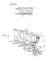
- FIG. 3 shows a brief section of the heat exchanger plate equipped with baffles.
- Figure 4 shows a perspective of the entire device in a charging station with several containers.
- FIG. 1 we can see the device comprising the reserves 1 and 2 of refrigerated fluid 3 by the coils 4 of the cold compressors 5 and 6.
- Each reserve comprises an outlet tube 7 and 8 and a return tube 9 and 10 of the refrigerated fluid 3.
- the tubes 7 and 8 each include a pump 11 and 12 for sending the refrigerated fluid into the exchanger plate 13 of the mobile container 14, which has baffles 15.
- a 4-way valve 16 manages the alternation of the two reserves 1 and 2.
- the flexible tubes 7, 8 of inlet and outlet 9, 10 of the refrigerated fluid are connected to the exchanger plate 13 by double valves 17 and 18 with quick coupling, these tubes are suspended by a hoist 19 with counterweight 20.
- a stay 21 maintains everything as well as the tubes and 4-way valve.
- An insulating capacity 29 makes it possible to preserve and isolate the tubes.
- the container 14 has at its base the orifices 22 for discharging the condensates and 23 for the connection of a water tube for cleaning.
- Diagrams A and B of FIG. 2 each show the two reserves 1, 2, and their coil 4, they are placed side by side and each have their cold compressor 5, 6.
- the exchanger plate 13 of the container 14 contains the baffles 15, allowing good circulation and distribution of the refrigerated fluid 3.
- the track valve 16 allows the management and the alternation of the two reserves: when the reserve 1 is filled with refrigerated fluid, the reserve 2 is empty, thus the tube 7 sends by its pump 11 the fluid in the exchanger plate 13, which has been emptied or at the same time empties of its fluid through the return tube 10 to the empty reserve 2 for reception which can then again refrigerate the fluid.
- the 4-way valve 16 therefore obstructed the circuit of the tubes: sending 8 and returning 9.
- each of the 2-way valves 24 and 25 allows the switching from one reserve to the other: the valve 24 manages the tubes 7 and 8, and the valve 25: 9 and 10.
- the exchanger plate 13 of FIG. 3 includes the baffles 15 allowing a better distribution of the refrigerated fluid 3. The fluid is renewed each time the container is returned or loaded.
- the device recharges a container 14.
- a recharging station 28 can thus be constituted at the places of departure and arrival of the containers by a series of devices.
Landscapes
- Engineering & Computer Science (AREA)
- Chemical & Material Sciences (AREA)
- Combustion & Propulsion (AREA)
- Physics & Mathematics (AREA)
- Mechanical Engineering (AREA)
- Thermal Sciences (AREA)
- General Engineering & Computer Science (AREA)
- Devices That Are Associated With Refrigeration Equipment (AREA)
Claims (5)
- Einrichtung zur Regeneration und Übertragung von positiven und negativen Wärmeinhalten (Joule bzw. Frigories), diese Einrichtung dazu ausgebildet, um die sofortige Beschickung eines Plattenwärmeaustauschers (13) mit negativem Wäremeinhalt (Frigories) 13 zu ermöglichen, und zwar eines Plattenwärmeaustauschers (13), der dazu bestimmt ist, einen Behälter oder einen mobilen Kühlhaltewagen (14) während seines Transports kühlzuhalten,dadurch gekennzeichnet,daß diese Einrichtung mindestens eine permanent gekühlte Reserve (1, 2) für ein gefriergeschütztes Fluid (3) umfaßt, welche Reserve - angekuppelt an ein Netz von Vorlaufrohren (7, 8) und Rücklaufrohren (9, 10) - die direkte Nachfüllung des Plattenwärmeaustauschers (13) des Behälters mit gekühltem Fluid (3) erlaubt und daß die Einrichtung eine weitere Reserve (2, 1) umfaßt, welche ebenfalls an das besagte Netz von Rohren (7 - 10) angekuppelt ist und die Wiedergewinnung des Rücklauffluids gestattet, wenn dieses nach Abgabe seines Kälteinhalts von dem Plattenwärmeaustauscher (13) zurückkommt,um dieses erneut abzukühlen, und daß Rohrschlangen (4) bleibend in jeder der Reserven (1, 2) installiert und ständig mittels eines Kältekompressors (5 und 6) gukühlt sind, welcher der jeweiligen Reserve zugeordnet ist, um das in der jeweiligen Reserve vorhandene Fluid zu kühlen.
- Einrichtung nach Anspruch 1,dadurch gekennzeichnet,daß jede der Reserven (1 und 2) alternierend arbeitet, um entweder das gefriergeschützte Fluid (3) zu kühlen oder zu regenerieren, wobei eine erste Reserve (1 oder 2) dazu dient, das Fluid (3) zu kühlen und den Plattenwärmeaustauscher (13) neu zu beschicken und wobei die zweite Reserve (2 oder 1) dazu dient, das von dem Plattenwärmeaustauscher (13) zurücklaufende Fluid zu sammeln, um es in dieser zweiten Reserve zu regenerieren mit dem Ziele, daß dieses zurücklaufende Fluid später in den Plattenwärmeaustauscher (13) zurückgeführt wird, der dem bereits genannten oder einem anderen Behälter (14) zugeordnet ist, wobei dann die erste Reserve wieder das Rücklauffluid aufnimmt usw.
- Einrichtung nach Anspruch 2,dadurch gekennzeichnet,daß der alternierende Einsatz der Reserven (1 und 2) durch ein 4-Wegeventil (16) oder durch zwei 2-Wegeventile (24, 25) manueller oder motorisierter Art gesteuert wird, wobei im ersteren Fall durch das 4-Wegeventil (16) das Rohrnetz mit allen vier Rohren (7, 8, 9, 10) und im letzteren Fall durch die zwei 2-Wegeventile (24, 25) das Rohrnetz mit jeweils zwei Rohren (7, 10 bzw. 8, 9) gesteuert wird mit der Folge des automatischen Fluidzulaufs (3) von einer Reserve zu dem Plattenwärmeaustauscher (13) und des Fluidrücklaufs von diesem Plattenwärmeaustauscher zu der jeweils zweiten Reserve und umgekehrt.
- Einrichtung nach Anspruch 1,dadurch gekennzeichnet,daß der Plattenwärmeaustauscher (13) Ablenkteile (15) im Hinblick auf eine verbesserte Verteilung und Akkumulation des Kälteinhalts des Fluids (3) besitzt.
- Einrichtung nach einem der vorangehenden Ansprüche,dadurch gekennzeichnet,daß der Behälter (14) Kondensatableitungsmittel (22) umfaßt und daß ein Rohr- und Düsennetz (23) zur Reinigung des Behälters (14) vorgesehen ist, welches unter Einsatz von Wasser oder Dampf arbeitet.
Applications Claiming Priority (3)
| Application Number | Priority Date | Filing Date | Title |
|---|---|---|---|
| FR9206161A FR2691237B1 (fr) | 1992-05-15 | 1992-05-15 | Dispositif de regeneration de joules ou de frigories pour module d'accumulation et de distribution de froid. |
| FR9206161 | 1992-05-15 | ||
| PCT/FR1993/000471 WO1993023712A1 (fr) | 1992-05-15 | 1993-05-14 | Dispositif de regeneration de joules ou frigories pour module d'accumulation de froid |
Publications (2)
| Publication Number | Publication Date |
|---|---|
| EP0639256A1 EP0639256A1 (de) | 1995-02-22 |
| EP0639256B1 true EP0639256B1 (de) | 1996-04-10 |
Family
ID=9430002
Family Applications (1)
| Application Number | Title | Priority Date | Filing Date |
|---|---|---|---|
| EP93910123A Expired - Lifetime EP0639256B1 (de) | 1992-05-15 | 1993-05-14 | Einrichtung zur regeneration von wärme oder kälte für ein kältespeichermodul |
Country Status (5)
| Country | Link |
|---|---|
| EP (1) | EP0639256B1 (de) |
| DE (1) | DE69302170T2 (de) |
| ES (1) | ES2086226T3 (de) |
| FR (1) | FR2691237B1 (de) |
| WO (1) | WO1993023712A1 (de) |
Families Citing this family (14)
| Publication number | Priority date | Publication date | Assignee | Title |
|---|---|---|---|---|
| FR2725265B1 (fr) * | 1994-09-30 | 1996-12-13 | Grandi Rene Vincent | Dispositif de regulation et de transfert de fluides frigorifiques ou caloriques pour conteneurs de transport |
| FR2735852B1 (fr) * | 1995-06-23 | 1997-09-12 | Electro Calorique | Chariot isotherme et installation pour assurer le refroidissement de chariots isothermes |
| NO954600A (no) * | 1995-11-14 | 1997-04-28 | Kvaerner Asa | Fremgangsmåte til kjøling av beholdere samt et kjølesystem for utførelse av fremgangsmåten |
| NL1003182C2 (nl) * | 1996-05-22 | 1997-03-25 | Hermanus Albertus Kosse | Koelinrichting, transportmiddel voorzien van koelinrichting, houder en samenstel van koelinrichting en houder. |
| GB2324852A (en) * | 1997-02-06 | 1998-11-04 | Ind Design Consultancy Limited | Controlling the temperature of products during distribution |
| FR2770897B1 (fr) * | 1997-11-10 | 2000-01-28 | Kamal Oulounis | Appareil refroidisseur d'eau monobloc |
| NL1012704C2 (nl) * | 1999-07-26 | 2001-01-29 | Gerardus Johannus Wilhelmus He | Inrichting en werkwijze voor het koelen van portioneerapparatuur. |
| NL1019756C2 (nl) * | 2002-01-16 | 2003-07-17 | Ecofys B V | Werkwijze voor het koelen of verwarmen van een transportmiddel, en een transportmiddel. |
| FR2868671B1 (fr) * | 2004-04-07 | 2008-08-01 | Electro Calorique Soc Par Acti | Chariot isotherme et installation pour assurer le refroidissement de chariots isothermes |
| DE102006001781A1 (de) * | 2006-01-12 | 2007-07-19 | Hubert Goseling | Verfahren zum Betrieb eines Speiseverteilsystems und Vorkühleinrichtung |
| US20110067852A1 (en) * | 2009-09-21 | 2011-03-24 | David Scott Farrar | Temperature controlled cargo containers |
| US10752434B2 (en) * | 2009-09-21 | 2020-08-25 | Sonoca Development, Inc. | Temperature controlled cargo containers |
| DE102010043245A1 (de) * | 2010-11-03 | 2012-05-03 | BSH Bosch und Siemens Hausgeräte GmbH | Kältegerät mit Pufferspeicher |
| US9212751B2 (en) * | 2012-09-28 | 2015-12-15 | Robertshaw Controls Company | Valve system and method |
Family Cites Families (3)
| Publication number | Priority date | Publication date | Assignee | Title |
|---|---|---|---|---|
| FR446689A (fr) * | 1911-10-07 | 1912-12-12 | Charles Theryc | Fourgons frigorifiques transportables aménagés en vue de constituer des entrepots urbains ou régionaux pour la conservation des poissons, viandes et autres denrées |
| FR2652885B1 (fr) * | 1988-09-14 | 1994-05-20 | Rene Grandi | Dispositif a echangeur accumulateur de frigories a raccord rapide, avec nourrice d'accumulation a reserve pour compensation de perte de gaz refrigerant. |
| CH680085A5 (de) * | 1989-08-10 | 1992-06-15 | Spectron Laser Gmbh |
-
1992
- 1992-05-15 FR FR9206161A patent/FR2691237B1/fr not_active Expired - Fee Related
-
1993
- 1993-05-14 DE DE69302170T patent/DE69302170T2/de not_active Expired - Fee Related
- 1993-05-14 EP EP93910123A patent/EP0639256B1/de not_active Expired - Lifetime
- 1993-05-14 WO PCT/FR1993/000471 patent/WO1993023712A1/fr not_active Ceased
- 1993-05-14 ES ES93910123T patent/ES2086226T3/es not_active Expired - Lifetime
Also Published As
| Publication number | Publication date |
|---|---|
| FR2691237B1 (fr) | 1996-05-10 |
| FR2691237A1 (fr) | 1993-11-19 |
| ES2086226T3 (es) | 1996-06-16 |
| DE69302170T2 (de) | 1996-08-22 |
| WO1993023712A1 (fr) | 1993-11-25 |
| DE69302170D1 (de) | 1996-05-15 |
| EP0639256A1 (de) | 1995-02-22 |
Similar Documents
| Publication | Publication Date | Title |
|---|---|---|
| EP0639256B1 (de) | Einrichtung zur regeneration von wärme oder kälte für ein kältespeichermodul | |
| EP0848800B1 (de) | Bewegbarer karren für warme und kalte fertiggericht-tabletts mit mitteln zur erwärmung und kühlung | |
| FR2487057A1 (fr) | Procede et appareil servant a la production et a l'utilisation de la glace pour stockage a basse temperature | |
| FR2611383A1 (fr) | Appareils de refrigeration utilisant un materiau d'accumulation de froid | |
| FR2689222A1 (fr) | Dispositif de transfert et d'accumulation de frigories ou de calories, pour la conservation de produits dans un chariot ou un container. | |
| CA2296299A1 (fr) | Chariot comportant un dispositif de refroidissement pouvant etre mis en oeuvre a l'instant choisi par l'utilisateur et procede pour apporter un mets rechauffe | |
| FR2652885A1 (fr) | Dispositif a echangeur accumulateur de frigories a raccord rapide, avec nourrice d'accumulation a reserve pour compensation de perte de gaz refrigerant. | |
| FR2824388A1 (fr) | Generateur de froid pour installation de climatisation de vehicule | |
| FR2760826A1 (fr) | Chariot refrigere et installation de rechargement en agent refrigerant | |
| EP0781394B1 (de) | Vorrichtung zur geregelten kälteübertragung zwischen einem kältespeicher und einem kälteraum | |
| FR2869272A1 (fr) | Installation de collecte et de transport de liquides refroidis, notamment de liquides alimentaires tels que du lait | |
| FR2815024A1 (fr) | Distributeur autonome ou non, mobile ou fixe, de boisson refrigeree equipe de deux moyens refrigerants individuels ou simultanes | |
| FR2820196A1 (fr) | Procede de maintien sous froid des trolleys a bord des avions assurant aussi le chauffage ou le maintien a chaud ainsi que l'ensemble du dispositif correspondant | |
| GB2324852A (en) | Controlling the temperature of products during distribution | |
| US2566301A (en) | Portable refrigeration box | |
| FR2752614A1 (fr) | Dispositif destine au nettoyage des installations et equipements de production et de transport de chaleur ou de froid utilisant un fluide caloporteur liquide | |
| FR2774748A1 (fr) | Conteneur que l'on peut refroidir a l'instant que l'on veut | |
| EP1934537B1 (de) | Trockeneisbehälter mit zwei behältnissen für isotherm-container | |
| JP2010504497A (ja) | 冷却ステーション | |
| CN215176346U (zh) | 单元配送箱及具有其的物流配送车 | |
| JPH0618165Y2 (ja) | 自動連続食品冷凍装置 | |
| FR2752288A1 (fr) | Dispositif d'accumulation et de transfert de frigories et installation pour sa mise en oeuvre | |
| JP6762625B2 (ja) | コンテナ型急速凍結冷凍保存作業ステーションプラント | |
| US7740053B2 (en) | Method of cooling or heating a means of transport and a means of transport | |
| US5878595A (en) | Compact portable icemaker |
Legal Events
| Date | Code | Title | Description |
|---|---|---|---|
| PUAI | Public reference made under article 153(3) epc to a published international application that has entered the european phase |
Free format text: ORIGINAL CODE: 0009012 |
|
| 17P | Request for examination filed |
Effective date: 19941103 |
|
| AK | Designated contracting states |
Kind code of ref document: A1 Designated state(s): BE DE DK ES FR GB IE IT NL PT SE |
|
| 17Q | First examination report despatched |
Effective date: 19950320 |
|
| GRAH | Despatch of communication of intention to grant a patent |
Free format text: ORIGINAL CODE: EPIDOS IGRA |
|
| GRAA | (expected) grant |
Free format text: ORIGINAL CODE: 0009210 |
|
| AK | Designated contracting states |
Kind code of ref document: B1 Designated state(s): BE DE DK ES FR GB IE IT NL PT SE |
|
| PG25 | Lapsed in a contracting state [announced via postgrant information from national office to epo] |
Ref country code: DK Effective date: 19960410 |
|
| REF | Corresponds to: |
Ref document number: 69302170 Country of ref document: DE Date of ref document: 19960515 |
|
| REG | Reference to a national code |
Ref country code: IE Ref legal event code: FG4D Free format text: 67945 |
|
| ITF | It: translation for a ep patent filed | ||
| REG | Reference to a national code |
Ref country code: ES Ref legal event code: FG2A Ref document number: 2086226 Country of ref document: ES Kind code of ref document: T3 |
|
| SC4A | Pt: translation is available |
Free format text: 960423 AVAILABILITY OF NATIONAL TRANSLATION |
|
| GBT | Gb: translation of ep patent filed (gb section 77(6)(a)/1977) |
Effective date: 19960715 |
|
| PG25 | Lapsed in a contracting state [announced via postgrant information from national office to epo] |
Ref country code: IE Free format text: LAPSE BECAUSE OF NON-PAYMENT OF DUE FEES Effective date: 19961107 |
|
| REG | Reference to a national code |
Ref country code: IE Ref legal event code: FD4D Ref document number: 67945 Country of ref document: IE |
|
| PLBE | No opposition filed within time limit |
Free format text: ORIGINAL CODE: 0009261 |
|
| STAA | Information on the status of an ep patent application or granted ep patent |
Free format text: STATUS: NO OPPOSITION FILED WITHIN TIME LIMIT |
|
| 26N | No opposition filed | ||
| REG | Reference to a national code |
Ref country code: FR Ref legal event code: CL |
|
| REG | Reference to a national code |
Ref country code: FR Ref legal event code: TP Ref country code: FR Ref legal event code: CL |
|
| REG | Reference to a national code |
Ref country code: GB Ref legal event code: IF02 |
|
| PGFP | Annual fee paid to national office [announced via postgrant information from national office to epo] |
Ref country code: GB Payment date: 20020913 Year of fee payment: 10 |
|
| PGFP | Annual fee paid to national office [announced via postgrant information from national office to epo] |
Ref country code: ES Payment date: 20020917 Year of fee payment: 10 Ref country code: PT Payment date: 20020917 Year of fee payment: 10 |
|
| PGFP | Annual fee paid to national office [announced via postgrant information from national office to epo] |
Ref country code: DE Payment date: 20020918 Year of fee payment: 10 |
|
| PGFP | Annual fee paid to national office [announced via postgrant information from national office to epo] |
Ref country code: SE Payment date: 20020925 Year of fee payment: 10 Ref country code: BE Payment date: 20020925 Year of fee payment: 10 |
|
| PGFP | Annual fee paid to national office [announced via postgrant information from national office to epo] |
Ref country code: NL Payment date: 20020930 Year of fee payment: 10 |
|
| PG25 | Lapsed in a contracting state [announced via postgrant information from national office to epo] |
Ref country code: GB Free format text: LAPSE BECAUSE OF NON-PAYMENT OF DUE FEES Effective date: 20030514 |
|
| PG25 | Lapsed in a contracting state [announced via postgrant information from national office to epo] |
Ref country code: SE Free format text: LAPSE BECAUSE OF NON-PAYMENT OF DUE FEES Effective date: 20030515 |
|
| PG25 | Lapsed in a contracting state [announced via postgrant information from national office to epo] |
Ref country code: ES Free format text: LAPSE BECAUSE OF NON-PAYMENT OF DUE FEES Effective date: 20030516 |
|
| PG25 | Lapsed in a contracting state [announced via postgrant information from national office to epo] |
Ref country code: BE Free format text: LAPSE BECAUSE OF NON-PAYMENT OF DUE FEES Effective date: 20030531 |
|
| BERE | Be: lapsed |
Owner name: *GRANDI RENE Effective date: 20030531 |
|
| PG25 | Lapsed in a contracting state [announced via postgrant information from national office to epo] |
Ref country code: PT Free format text: LAPSE BECAUSE OF NON-PAYMENT OF DUE FEES Effective date: 20031130 |
|
| PG25 | Lapsed in a contracting state [announced via postgrant information from national office to epo] |
Ref country code: NL Free format text: LAPSE BECAUSE OF NON-PAYMENT OF DUE FEES Effective date: 20031201 |
|
| PG25 | Lapsed in a contracting state [announced via postgrant information from national office to epo] |
Ref country code: DE Free format text: LAPSE BECAUSE OF NON-PAYMENT OF DUE FEES Effective date: 20031202 |
|
| EUG | Se: european patent has lapsed | ||
| GBPC | Gb: european patent ceased through non-payment of renewal fee |
Effective date: 20030514 |
|
| NLV4 | Nl: lapsed or anulled due to non-payment of the annual fee |
Effective date: 20031201 |
|
| REG | Reference to a national code |
Ref country code: PT Ref legal event code: MM4A Free format text: LAPSE DUE TO NON-PAYMENT OF FEES Effective date: 20031130 |
|
| REG | Reference to a national code |
Ref country code: ES Ref legal event code: FD2A Effective date: 20030516 |
|
| PG25 | Lapsed in a contracting state [announced via postgrant information from national office to epo] |
Ref country code: IT Free format text: LAPSE BECAUSE OF NON-PAYMENT OF DUE FEES;WARNING: LAPSES OF ITALIAN PATENTS WITH EFFECTIVE DATE BEFORE 2007 MAY HAVE OCCURRED AT ANY TIME BEFORE 2007. THE CORRECT EFFECTIVE DATE MAY BE DIFFERENT FROM THE ONE RECORDED. Effective date: 20050514 |
|
| PGFP | Annual fee paid to national office [announced via postgrant information from national office to epo] |
Ref country code: FR Payment date: 20070425 Year of fee payment: 15 |
|
| REG | Reference to a national code |
Ref country code: FR Ref legal event code: ST Effective date: 20090119 |
|
| PG25 | Lapsed in a contracting state [announced via postgrant information from national office to epo] |
Ref country code: FR Free format text: LAPSE BECAUSE OF NON-PAYMENT OF DUE FEES Effective date: 20080602 |