EP0638951B1 - Bleisäurebatterie - Google Patents
Bleisäurebatterie Download PDFInfo
- Publication number
- EP0638951B1 EP0638951B1 EP93111864A EP93111864A EP0638951B1 EP 0638951 B1 EP0638951 B1 EP 0638951B1 EP 93111864 A EP93111864 A EP 93111864A EP 93111864 A EP93111864 A EP 93111864A EP 0638951 B1 EP0638951 B1 EP 0638951B1
- Authority
- EP
- European Patent Office
- Prior art keywords
- cap
- rib
- partition wall
- lead acid
- acid battery
- Prior art date
- Legal status (The legal status is an assumption and is not a legal conclusion. Google has not performed a legal analysis and makes no representation as to the accuracy of the status listed.)
- Expired - Lifetime
Links
Images



Classifications
-
- H—ELECTRICITY
- H01—ELECTRIC ELEMENTS
- H01M—PROCESSES OR MEANS, e.g. BATTERIES, FOR THE DIRECT CONVERSION OF CHEMICAL ENERGY INTO ELECTRICAL ENERGY
- H01M10/00—Secondary cells; Manufacture thereof
- H01M10/42—Methods or arrangements for servicing or maintenance of secondary cells or secondary half-cells
- H01M10/48—Accumulators combined with arrangements for measuring, testing or indicating the condition of cells, e.g. the level or density of the electrolyte
- H01M10/486—Accumulators combined with arrangements for measuring, testing or indicating the condition of cells, e.g. the level or density of the electrolyte for measuring temperature
-
- H—ELECTRICITY
- H01—ELECTRIC ELEMENTS
- H01M—PROCESSES OR MEANS, e.g. BATTERIES, FOR THE DIRECT CONVERSION OF CHEMICAL ENERGY INTO ELECTRICAL ENERGY
- H01M10/00—Secondary cells; Manufacture thereof
- H01M10/06—Lead-acid accumulators
- H01M10/12—Construction or manufacture
-
- Y—GENERAL TAGGING OF NEW TECHNOLOGICAL DEVELOPMENTS; GENERAL TAGGING OF CROSS-SECTIONAL TECHNOLOGIES SPANNING OVER SEVERAL SECTIONS OF THE IPC; TECHNICAL SUBJECTS COVERED BY FORMER USPC CROSS-REFERENCE ART COLLECTIONS [XRACs] AND DIGESTS
- Y02—TECHNOLOGIES OR APPLICATIONS FOR MITIGATION OR ADAPTATION AGAINST CLIMATE CHANGE
- Y02E—REDUCTION OF GREENHOUSE GAS [GHG] EMISSIONS, RELATED TO ENERGY GENERATION, TRANSMISSION OR DISTRIBUTION
- Y02E60/00—Enabling technologies; Technologies with a potential or indirect contribution to GHG emissions mitigation
- Y02E60/10—Energy storage using batteries
-
- Y—GENERAL TAGGING OF NEW TECHNOLOGICAL DEVELOPMENTS; GENERAL TAGGING OF CROSS-SECTIONAL TECHNOLOGIES SPANNING OVER SEVERAL SECTIONS OF THE IPC; TECHNICAL SUBJECTS COVERED BY FORMER USPC CROSS-REFERENCE ART COLLECTIONS [XRACs] AND DIGESTS
- Y02—TECHNOLOGIES OR APPLICATIONS FOR MITIGATION OR ADAPTATION AGAINST CLIMATE CHANGE
- Y02P—CLIMATE CHANGE MITIGATION TECHNOLOGIES IN THE PRODUCTION OR PROCESSING OF GOODS
- Y02P70/00—Climate change mitigation technologies in the production process for final industrial or consumer products
- Y02P70/50—Manufacturing or production processes characterised by the final manufactured product
Definitions
- Such conventional structure which is for example described in JP-A-58201269, gives a good operation in mounting the pair of input and output terminals and the thermostat onto the terminal holder and then inserting the holder into the terminal box.
- contact between the thermostat and the partition wall is often made poor in the conventional structure, due to unstable mating between the terminal holder or unstable mating between the terminal holder and the terminal box.
- the primary object of the present invention is to solve the problems of the conventional structure as mentioned above and improve the structure for mounting a "thermoswitch” such as a thermostat or thermal protector as a protector onto the partition wall in lead acid batteries to protect the batteries from generated heat.
- a "thermoswitch” such as a thermostat or thermal protector as a protector onto the partition wall in lead acid batteries to protect the batteries from generated heat.
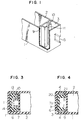
- Fig. 1 is a pictorial view of a partially sectioned part of the terminal box according to an embodiment of the present invention.
- Fig. 2 is a pictorial view showing the state of the terminal holder mounted according to an embodiment of the present invention.
- Fig. 3 is a top view showing the state of the thermostat contained in the terminal box according to an embodiment of the present invention.
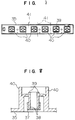
- Fig. 6 is a view showing the back side of the inter-mediate cap.
- a terminal box in which a pair of terminals for charge and discharge as output and input terminals and a thermoswitch are to be contained, is provided at one end of a battery container, the terminals are held by a terminal holder and inserted in the terminal box.
- the thermoswitch is held by a rib made monolithically with the terminal box and brought on one of the surfaces thereof in contact with a partition wall separating the terminal box from a cell chamber containing a cell element, as specified in appended claim 1.
- thermoswitch The measure of bringing the thermoswitch in close contact with the partition wall provides adequate heat conduction through the partition wall to the thermoswitch and thus allows the heat sensitivity of the thermoswitch to be increased, thereby raising the reliability of the thermoswitch on temperatures.
- Fig. 1 shows a battery container 1 according to the present invention, provided with a plurality of cell chambers 2 containing a cell element, and a terminal box 3 separated in the container from the cell chamber 2 through a partition wall 9 .
- the terminal box 3 is provided with a pair of windows 5 for exposing a pair of terminals 4 at the corners of the container.
- a rib 10 for holding a thermostat 7 , which is made monolithically with the partition wall 9 .
- the rib 10 is made by two pieces of an L-shaped cross section in such a manner that these pieces face each other and constitute a slit 11 therebetween.
- the partition wall 9 , two pieces constituting the rib 10 and slit 11 form a box shape.
- Fig. 2 shows a method of assembling the battery.
- a terminal holder 6 was provided at the back side thereof with a recess 14 which can moderately mate therein with the rib 10 .
- the recess was provided at the bottom thereof with a support-ing rib 15 inserted in the rib 10 to support the bottom of the thermostat 7 .
- Terminals 4 and 4' were mounted on the right and left sides of the holder 6 , respectively.
- the holder 6 was inserted into the terminal box 3 .
- the thermostat 7 was inserted into the box formed by the partition wall 9 and the rib 10 .
- the thermostat 7 was supported on the bottom thereof by the supporting rib 15 inserted through the slit 11 into the rib 10 .
- the support-ing rib 15 defined the position of the thermostat.
- the heat-insulating air layer 13 is formed for preventing the heat transferred from the rib 10 to the thermostat 7 from being transferred to or removed by the terminal holder 6 . Moreover, the bottom of the thermostat 7 is supported by the supporting rib 15 to prevent the conduction and emission of heat from the bottom of the thermostat 7 .
- the supporting rib 15 is not provided at the rib 10 made monolithically with the partition wall 9 but at the terminal holder 6 to avoid the lowering of the moldability of the battery container, because forming the rib 10 in a box shape and providing the supporting rib 15 on the rib 10 would lower the strength of a metal mold (core) for forming the rib with the supporting rib.
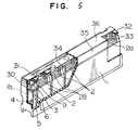
- the hold-er further contains a thermal protector 7a for protecting the battery.
- Lead wire 30 for one of the terminals of the thermal protector 7a is connected to one electrode pole 31 of the cell element 28 contained in the cell chamber adjacent to the terminal box 3 .
- a lead wire for the other of the terminals of the thermal protector 7a is connected to one of the output and input terminals 4 .
- the thermal protector 7a also functions as a lead wire for connecting one of the output and input terminals to any one of the positive and negative electrodes of the cell element in the nearest cell chamber.
- a small projection is provided so as to extend upwardly on part of the partition wall 9 , at the top of which is provided an indent having a semicircular shape in cross section, and the lead wire 33 is mated to the semicircular indent and secured to be fixed in a form of straight line with the grasping force of the projection.
- the intermediate cap 35 is provided with cylindrical vents 38 on each of which a cap-type safety valve 37 is mounted, over a plurality of the cell chambers 2 in the battery container 1 .
- An annular recess is formed around the cylindrical vent 38 , with which the cap-type safety valve 37 is mated to the top of the vent 38 .
- a piece of the top cap 36 is provided so as to cover the safety valve 37 .
- Figs. 6 and 7 both show inversely the top and bottom of the intermediate cap 35 in the battery container-capped state (Fig. 5).
- the inter-mediate cap 35 has an inside vent 39 formed to project in the cell chamber, at the side opposite to that at which the vent 38 is provided.
- a rib 40 is formed around the inside vent 39 .
- the rib 40 is in a rectangular frame form and higher than the height of the inside vent 39 .
- the rib 40 supports the inside vent 39 via the bottom of the annular recess and, therefore, the mechanical strength of the vent 38 can be raised and the vent 38 and the bottom of the recess can be prevented from being bent downwardly when the cap-type safety valve 37 is mounted onto the vent 38.
- the safety valve can reliably and easily be mounted.
- a liquid-absorbing sheet is preferably provided between the intermediate cap and the top cap.
- the liquid-absorbing sheet in addition to the direct adherence between intermediate cap 35 and the top cap 36 does not permit an electrolyte to leak out of the battery even if a large amount of the electrolyte leaks out through the valve during operation of the battery.
- the liquid-absorbing sheet can absorb and fix the electrolyte and sealing oil.
- the intermediate cap 35 is provided on the flat part of the top surface thereof with a plurality of small projections 42.
- the top cap 36 is provided on the back side thereof with pin-like projections 43 for fixing the relation in position between the intermediate cap 35 and the top cap 36.
- the intermediate cap 35 is provided with holes 44 corresponding to the pin-like projections 43.
- the liquid-absorbing sheet 46 has through-holes 45 provided to correspond to the small projections 42 and holes 44 and is mounted on the top of the inter-mediate cap 35.
- the pin-like projections 43 of the top cap 36 are allowed to pass through the through-holes 45 of the liquid-absorbing sheet 46 and then through the holes 44 , thus fixing the top cap 36 on the intermediate cap 35, and bringing the small projections 42 on the front side of the intermediate cap 35 in contact with the ribs 47 on the back side of the top cap 36. This contact is fused with ultrasonic wave.
- the liquid-absorbing sheet 46 is covered substantially over the entire top surface of the inter-mediate cap 35 , so that the electrolyte leaking out through the safety valve 37 can be absorbed by the sheet. A large amount of the electrolyte leaking out through the safety valve 37 when overcharged can be absorbed by the liquid-absorbing sheet 46 and prevented from leaking out.
Landscapes
- Engineering & Computer Science (AREA)
- Manufacturing & Machinery (AREA)
- Chemical & Material Sciences (AREA)
- Chemical Kinetics & Catalysis (AREA)
- Electrochemistry (AREA)
- General Chemical & Material Sciences (AREA)
- Sealing Battery Cases Or Jackets (AREA)
Claims (8)
- Bleisäurebatterie aufweisend einen Batteriebehälter (1) mit einer Mehrzahl von Zellenkammern (2) und an seinem einen Ende einem durch eine Abtrennwand (9) von der dem Ende zugewandten der Zellenkammern (2) abgetrennten Anschlußkasten (3), der ein Paar Lade- und Entladeanschlüsse (4, 4'), einen Thermoschalter (7, 7a) und einen das Paar Lade- und Entladeanschlüsse haltenden Anschlußhalter (6) aufweist, und ein in der Zellenkammer (2) enthaltenes Zellenelement (28), wobei eine der Oberflächen des Thermoschalters (7, 7a) in Kontakt mit der Abtrennwand (9) steht, gekennzeichnet durch eine zusammen mit der Abtrennwand (9) einstückig gebildete Rippe (10), die in solcher Weise zwei Stücke mit einem L-förmigen Querschnitt aufweist, daß diese Stücke einander zugewandt sind und zwischen sich einen Schlitz (11) bilden, und daß die Abtrennwand (9), die zwei die Rippe (10) bildenden Stücke und der Schlitz eine Kastenform bilden, um darin den Thermoschalter (7, 7a) aufzunehmen, wobei die der in Kontakt mit der Abtrennwand stehenden Oberfläche benachbarten Oberflächen des Thermoschalters (7, 7a) in Kontakt mit den Innenoberflächen der Rippe gebracht sind, um den Thermoschalter innerhalb der Rippe zu halten.
- Bleisäurebatterie nach Anspruch 1, bei der zwischen der Rippe (10) und dem Anschlußhalter (6) eine wärmeisolierende Luftschicht (13) vorgesehen ist.
- Bleisäurebatterie nach Anspruch 1, bei der der Anschlußhalter (6) ferner als Halterung zum Festlegen des Thermoschalters (7, 7a) in einer gegebenen Position wirkt.
- Bleisäurebatterie nach einem der vorstehenden Ansprüche, bei der an den Oberseiten der den Batteriebehälter (1) in die Zellenkammern (2) aufteilenden Abtrennwände (9) ein Bleidraht (33) angeordnet ist und einen der Anschlüsse (4) in dem Anschlußkasten (3) an einem der Anschlüsse des in der von dem Anschlußkasten (3) entferntesten Zellenkammer (2a) enthaltenden Zellenelements anschließt und eine Abdeckung (35) zum Abdecken des Batteriebehälters vorgesehen ist, die durch einen auf der Rückseite der Abdeckung (35) angeordneten Klebstoff an dem Batteriebehälter (1) angeklebt ist, wobei der Bleidraht (33) in dem Klebstoff eingebettet ist.
- Bleisäurebatterie nach Anspruch 4, bei der der Bleidraht (33) angepaßt ist und befestigt ist an an den Oberseiten der den Batteriebehälter in die Zellenkammern (2) aufteilenden Abtrennwände (9) vorgesehenen Einbuchtungen (34).
- Bleisäurebatterie nach Anspruch 5, bei der die Einbuchtung (34) zum Befestigen des Bleidrahts (33) eine Nut oder einen Schlitz mit einem einstückig mit der Abtrennwand (9) gebildeten und an der Oberseite der Abtrennwand (9) etwas vorstehenden kleinen Vorsprung ist.
- Abgeschlossene Bleisäurebatterie nach einem der vorstehenden Ansprüche ferner mit: einer Zwischenabdeckung (35) für den Betteriebehälter (1), die an ihrer Oberseite mit nach oben weisenden Sicherheitsventilen (37) versehen ist, einer die Zwischenabdeckung (35) abdeckenden Oberseitenabdeckung (36), einer zwischen der Zwischenabdeckung (35) und der Oberseitenabdekkung (36) angeordneten Flüssigkeitabsorbtionsschicht (46), wobei die Oberseitenabdeckung (36) an ihrer Rückseite mit einer Mehrzahl von Vorsprüngen (43) und/oder Löchern versehen ist und die Zwischenabdeckung an den den Positionen dieser Vorsprünge (43) und/oder Löcher entsprechenden Positionen an der Vorderseite der Zwischenabdeckung mit Löchern (44) und/oder Vorsprüngen versehen ist, die Oberseitenabdeckung (36) und die Zwischenabdeckung (35) mit den zueinander passenden entsprechenden Löchern (44) und Vorsprüngen (43) befestigt sind, die Zwischenabdeckung (35) an dem flachen Abschnitt ihrer Vorderseite mit einer Mehrzahl von kleinen Vorsprüngen (42) versehen ist und die Flüssigkeitsabsorbtionsschicht (46) an den den Positionen dieser kleinen Vorsprünge (42) entsprechenden Positionen mit Durchgangslöchern (45) versehen ist und die kleinen Vorsprünge (42) der Zwischenabdeckung (35) durch Ultraschallschmelzen bzw. -schweißen durch die Durchgangslöcher (45) an der Rückseite der Oberseitenabdeckung (36) angehaftet bzw. befestigt sind.
- Abgeschlossene Bleisäurebatterie nach einem der vorstehenden Ansprüche mit einer Batterieabdeckung (35) mit daran über jeder der Zellenkammern (2) nach oben weisend gebildeten zylindrischen Entlüftungen (38), die mit abdeckkappenartigen Sicherheitsventilen (37) abgedeckt sind, wobei die Abdekkung mit einem auf ihrer Rückseite angeordneten Klebstoff auf den Batteriebehälter (1) geklebt ist, wobei die Entlüftungen (38) an ihrer Rückseite mit Sicherheitsventilen (37) abgedeckt sind, die Entlüftung (38) eine Innenentlüftung (39) aufweist, die sich in einer entgegengesetzten Richtung zu derjenigen der Entlüftung (38) erstreckt und von einer ringförmigen Rippe (40) mit einer größeren Höhe als die der Innenwände der Entlüftung (39) umgeben ist.
Priority Applications (3)
| Application Number | Priority Date | Filing Date | Title |
|---|---|---|---|
| US08/093,708 US5419983A (en) | 1993-07-20 | 1993-07-20 | Lead acid battery |
| EP93111864A EP0638951B1 (de) | 1993-07-20 | 1993-07-23 | Bleisäurebatterie |
| DE69323307T DE69323307T2 (de) | 1993-07-23 | 1993-07-23 | Bleisäurebatterie |
Applications Claiming Priority (2)
| Application Number | Priority Date | Filing Date | Title |
|---|---|---|---|
| US08/093,708 US5419983A (en) | 1993-07-20 | 1993-07-20 | Lead acid battery |
| EP93111864A EP0638951B1 (de) | 1993-07-20 | 1993-07-23 | Bleisäurebatterie |
Publications (3)
| Publication Number | Publication Date |
|---|---|
| EP0638951A2 EP0638951A2 (de) | 1995-02-15 |
| EP0638951A3 EP0638951A3 (de) | 1995-04-26 |
| EP0638951B1 true EP0638951B1 (de) | 1999-01-27 |
Family
ID=26133340
Family Applications (1)
| Application Number | Title | Priority Date | Filing Date |
|---|---|---|---|
| EP93111864A Expired - Lifetime EP0638951B1 (de) | 1993-07-20 | 1993-07-23 | Bleisäurebatterie |
Country Status (2)
| Country | Link |
|---|---|
| US (1) | US5419983A (de) |
| EP (1) | EP0638951B1 (de) |
Families Citing this family (13)
| Publication number | Priority date | Publication date | Assignee | Title |
|---|---|---|---|---|
| EP1149744A3 (de) * | 1994-06-22 | 2001-12-19 | Intra Development A/S | Diebstahlgesicherte Batterie |
| FR2770035B1 (fr) * | 1997-10-20 | 1999-12-10 | Alsthom Cge Alcatel | Batterie monobloc contenant un dispositif de mesure de la temperature interne |
| USD419132S (en) * | 1998-08-20 | 2000-01-18 | Matsushita Electric Industrial Co., Ltd. | Storage battery |
| USD418477S (en) * | 1998-08-20 | 2000-01-04 | Matsushita Electric Industrial Co., Ltd. | Storage battery |
| USD418807S (en) * | 1998-08-20 | 2000-01-11 | Matsushita Electric Industrial Co., Ltd. | Storage battery |
| SE524561C2 (sv) * | 2000-04-25 | 2004-08-24 | Intra Internat Ab | Strömmätningskrets med två mätområden |
| US20040113494A1 (en) * | 2000-09-01 | 2004-06-17 | Karuppana Samy V. | Daytime running light control using an intelligent power management system |
| US7875375B2 (en) | 2004-08-05 | 2011-01-25 | Toyota Jidosha Kabushiki Kaisha | Battery module, battery pack, and method for producing the battery module |
| JP4815016B2 (ja) * | 2009-07-17 | 2011-11-16 | パナソニック株式会社 | 電池接続部材とそれを用いた電池モジュール |
| TWI524578B (zh) * | 2013-12-31 | 2016-03-01 | 原瑞電池科技股份有限公司 | 電池模組 |
| CN111384328A (zh) | 2018-12-29 | 2020-07-07 | 比亚迪股份有限公司 | 电池托盘、动力电池包及车辆 |
| CN110190211B (zh) | 2018-12-29 | 2020-03-31 | 比亚迪股份有限公司 | 电池托盘、动力电池包及车辆 |
| US12230820B2 (en) | 2019-01-09 | 2025-02-18 | Byd Company Limited | Power battery pack and electric vehicle |
Family Cites Families (19)
| Publication number | Priority date | Publication date | Assignee | Title |
|---|---|---|---|---|
| US4233370A (en) * | 1979-04-30 | 1980-11-11 | General Battery Corporation | Snap-through anti-ignition vent cap for lead acid storage batteries |
| JPS58142759A (ja) * | 1982-02-19 | 1983-08-24 | Matsushita Electric Ind Co Ltd | 蓄電池 |
| JPS58201269A (ja) * | 1982-05-20 | 1983-11-24 | Matsushita Electric Ind Co Ltd | 温度センサ−付き蓄電池 |
| DE3436290A1 (de) * | 1983-10-08 | 1985-04-25 | Honda Giken Kogyo K.K., Tokio/Tokyo | Abgedichtete blei-saeure-batterie |
| JPS6231963A (ja) * | 1985-08-02 | 1987-02-10 | Matsushita Electric Ind Co Ltd | 密閉形鉛蓄電池 |
| JPS62249352A (ja) * | 1986-04-22 | 1987-10-30 | Shin Kobe Electric Mach Co Ltd | 密閉形鉛蓄電池の製造法 |
| JPS636854A (ja) * | 1986-06-27 | 1988-01-12 | Hitachi Ltd | 異物検査装置 |
| DE3643920A1 (de) * | 1986-12-22 | 1988-06-23 | Bosch Gmbh Robert | Bleiakkumulator in blockausfuehrung |
| JPS63187554A (ja) * | 1987-01-27 | 1988-08-03 | Matsushita Electric Ind Co Ltd | 密閉形鉛蓄電池 |
| US4859546A (en) * | 1987-08-21 | 1989-08-22 | Globe-Union Inc. | Battery explosion attenuation material and method |
| US4780379A (en) * | 1987-10-06 | 1988-10-25 | Gates Energy Products, Inc. | Multicell recombinant lead-acid battery with vibration resistant intercell connector |
| US4885524A (en) * | 1988-04-15 | 1989-12-05 | William J. Goldcamp | Vehicle battery system |
| JPH0828212B2 (ja) * | 1988-10-28 | 1996-03-21 | 松下電器産業株式会社 | 密閉形鉛蓄電池 |
| JPH04106883A (ja) * | 1990-08-24 | 1992-04-08 | Murata Mfg Co Ltd | 充電検知器 |
| JP3003243B2 (ja) * | 1991-03-18 | 2000-01-24 | ソニー株式会社 | バッテリー |
| JP3006242B2 (ja) * | 1991-12-02 | 2000-02-07 | 松下電器産業株式会社 | 小形シール鉛蓄電池 |
| JPH05217567A (ja) * | 1992-02-07 | 1993-08-27 | Matsushita Electric Ind Co Ltd | 密閉型鉛蓄電池 |
| JP3042131B2 (ja) * | 1992-02-07 | 2000-05-15 | 松下電器産業株式会社 | 鉛蓄電池 |
| JP3089789B2 (ja) * | 1992-02-07 | 2000-09-18 | 松下電器産業株式会社 | 鉛蓄電池 |
-
1993
- 1993-07-20 US US08/093,708 patent/US5419983A/en not_active Expired - Lifetime
- 1993-07-23 EP EP93111864A patent/EP0638951B1/de not_active Expired - Lifetime
Also Published As
| Publication number | Publication date |
|---|---|
| EP0638951A3 (de) | 1995-04-26 |
| US5419983A (en) | 1995-05-30 |
| EP0638951A2 (de) | 1995-02-15 |
Similar Documents
| Publication | Publication Date | Title |
|---|---|---|
| EP0638951B1 (de) | Bleisäurebatterie | |
| EP0917218A2 (de) | Batterieeinheit und tragbare batteriebetriebene Vorrichtung mit einer solchen Batterieeinheit | |
| RU2317614C1 (ru) | Портативный батарейный источник питания улучшенной конструкции | |
| US4121017A (en) | Portable rechargeable lead-acid battery | |
| US20050208345A1 (en) | Secondary battery of assemble-type structure | |
| JP5479302B2 (ja) | バッテリアセンブリ | |
| JP5270637B2 (ja) | バッテリ組立体 | |
| KR20050020357A (ko) | 파우치 케이스 및 이를 구비한 파우치형 이차 전지 | |
| CN101174706B (zh) | 二次电池及其制造方法 | |
| KR20090132490A (ko) | 배터리 팩 및 그 제조 방법 | |
| KR100571247B1 (ko) | 리튬이온 이차전지 | |
| CN101573807A (zh) | 具有优良的可生产性和结构稳定性的电池组 | |
| EP2328200B1 (de) | Batterieanordnung | |
| US20100151281A1 (en) | Battery pack | |
| WO1999014814A1 (fr) | Batterie d'alimentation et element a ctp integre a ladite batterie | |
| KR20240012290A (ko) | 배터리 모듈 및, 이를 포함하는 배터리 팩 및 이를 포함하는 자동차 | |
| EP2378591A1 (de) | Sekundärbatterie | |
| KR100768178B1 (ko) | 리튬 이차 전지 | |
| CN121394719A (zh) | 端盖组件、储能装置和用电设备 | |
| JP2002110115A (ja) | パック電池 | |
| JP2003017020A (ja) | パック電池 | |
| KR100858793B1 (ko) | 보강용 비이드가 형성된 캡 조립체 및, 그것을 구비한라운드형 2 차 전지 | |
| CN102104124B (zh) | 电池组 | |
| JP3328475B2 (ja) | 蓄電池の電槽 | |
| KR20110060165A (ko) | 배터리 팩 |
Legal Events
| Date | Code | Title | Description |
|---|---|---|---|
| PUAI | Public reference made under article 153(3) epc to a published international application that has entered the european phase |
Free format text: ORIGINAL CODE: 0009012 |
|
| AK | Designated contracting states |
Kind code of ref document: A2 Designated state(s): DE FR GB |
|
| PUAL | Search report despatched |
Free format text: ORIGINAL CODE: 0009013 |
|
| AK | Designated contracting states |
Kind code of ref document: A3 Designated state(s): DE FR GB |
|
| 17P | Request for examination filed |
Effective date: 19950601 |
|
| 17Q | First examination report despatched |
Effective date: 19970110 |
|
| GRAG | Despatch of communication of intention to grant |
Free format text: ORIGINAL CODE: EPIDOS AGRA |
|
| GRAG | Despatch of communication of intention to grant |
Free format text: ORIGINAL CODE: EPIDOS AGRA |
|
| GRAH | Despatch of communication of intention to grant a patent |
Free format text: ORIGINAL CODE: EPIDOS IGRA |
|
| GRAH | Despatch of communication of intention to grant a patent |
Free format text: ORIGINAL CODE: EPIDOS IGRA |
|
| GRAA | (expected) grant |
Free format text: ORIGINAL CODE: 0009210 |
|
| AK | Designated contracting states |
Kind code of ref document: B1 Designated state(s): DE FR GB |
|
| REF | Corresponds to: |
Ref document number: 69323307 Country of ref document: DE Date of ref document: 19990311 |
|
| ET | Fr: translation filed | ||
| PLBE | No opposition filed within time limit |
Free format text: ORIGINAL CODE: 0009261 |
|
| STAA | Information on the status of an ep patent application or granted ep patent |
Free format text: STATUS: NO OPPOSITION FILED WITHIN TIME LIMIT |
|
| 26N | No opposition filed | ||
| REG | Reference to a national code |
Ref country code: GB Ref legal event code: IF02 |
|
| PGFP | Annual fee paid to national office [announced via postgrant information from national office to epo] |
Ref country code: FR Payment date: 20090710 Year of fee payment: 17 |
|
| PGFP | Annual fee paid to national office [announced via postgrant information from national office to epo] |
Ref country code: GB Payment date: 20090722 Year of fee payment: 17 Ref country code: DE Payment date: 20090716 Year of fee payment: 17 |
|
| GBPC | Gb: european patent ceased through non-payment of renewal fee |
Effective date: 20100723 |
|
| REG | Reference to a national code |
Ref country code: FR Ref legal event code: ST Effective date: 20110331 |
|
| PG25 | Lapsed in a contracting state [announced via postgrant information from national office to epo] |
Ref country code: DE Free format text: LAPSE BECAUSE OF NON-PAYMENT OF DUE FEES Effective date: 20110201 |
|
| REG | Reference to a national code |
Ref country code: DE Ref legal event code: R119 Ref document number: 69323307 Country of ref document: DE Effective date: 20110201 |
|
| PG25 | Lapsed in a contracting state [announced via postgrant information from national office to epo] |
Ref country code: FR Free format text: LAPSE BECAUSE OF NON-PAYMENT OF DUE FEES Effective date: 20100802 |
|
| PG25 | Lapsed in a contracting state [announced via postgrant information from national office to epo] |
Ref country code: GB Free format text: LAPSE BECAUSE OF NON-PAYMENT OF DUE FEES Effective date: 20100723 |