EP0637504A2 - Reifenform und Verfahren zum Formen von Reifen - Google Patents
Reifenform und Verfahren zum Formen von Reifen Download PDFInfo
- Publication number
- EP0637504A2 EP0637504A2 EP94110865A EP94110865A EP0637504A2 EP 0637504 A2 EP0637504 A2 EP 0637504A2 EP 94110865 A EP94110865 A EP 94110865A EP 94110865 A EP94110865 A EP 94110865A EP 0637504 A2 EP0637504 A2 EP 0637504A2
- Authority
- EP
- European Patent Office
- Prior art keywords
- elements
- molding
- mold according
- tire
- edge
- Prior art date
- Legal status (The legal status is an assumption and is not a legal conclusion. Google has not performed a legal analysis and makes no representation as to the accuracy of the status listed.)
- Granted
Links
Images

Classifications
-
- B—PERFORMING OPERATIONS; TRANSPORTING
- B29—WORKING OF PLASTICS; WORKING OF SUBSTANCES IN A PLASTIC STATE IN GENERAL
- B29C—SHAPING OR JOINING OF PLASTICS; SHAPING OF MATERIAL IN A PLASTIC STATE, NOT OTHERWISE PROVIDED FOR; AFTER-TREATMENT OF THE SHAPED PRODUCTS, e.g. REPAIRING
- B29C33/00—Moulds or cores; Details thereof or accessories therefor
- B29C33/30—Mounting, exchanging or centering
- B29C33/301—Modular mould systems [MMS], i.e. moulds built up by stacking mould elements, e.g. plates, blocks, rods
- B29C33/302—Assembling a large number of mould elements to constitute one cavity
-
- B—PERFORMING OPERATIONS; TRANSPORTING
- B29—WORKING OF PLASTICS; WORKING OF SUBSTANCES IN A PLASTIC STATE IN GENERAL
- B29C—SHAPING OR JOINING OF PLASTICS; SHAPING OF MATERIAL IN A PLASTIC STATE, NOT OTHERWISE PROVIDED FOR; AFTER-TREATMENT OF THE SHAPED PRODUCTS, e.g. REPAIRING
- B29C33/00—Moulds or cores; Details thereof or accessories therefor
- B29C33/10—Moulds or cores; Details thereof or accessories therefor with incorporated venting means
-
- B—PERFORMING OPERATIONS; TRANSPORTING
- B29—WORKING OF PLASTICS; WORKING OF SUBSTANCES IN A PLASTIC STATE IN GENERAL
- B29D—PRODUCING PARTICULAR ARTICLES FROM PLASTICS OR FROM SUBSTANCES IN A PLASTIC STATE
- B29D30/00—Producing pneumatic or solid tyres or parts thereof
- B29D30/06—Pneumatic tyres or parts thereof (e.g. produced by casting, moulding, compression moulding, injection moulding, centrifugal casting)
- B29D30/0601—Vulcanising tyres; Vulcanising presses for tyres
- B29D30/0606—Vulcanising moulds not integral with vulcanising presses
-
- B—PERFORMING OPERATIONS; TRANSPORTING
- B29—WORKING OF PLASTICS; WORKING OF SUBSTANCES IN A PLASTIC STATE IN GENERAL
- B29D—PRODUCING PARTICULAR ARTICLES FROM PLASTICS OR FROM SUBSTANCES IN A PLASTIC STATE
- B29D30/00—Producing pneumatic or solid tyres or parts thereof
- B29D30/06—Pneumatic tyres or parts thereof (e.g. produced by casting, moulding, compression moulding, injection moulding, centrifugal casting)
- B29D30/08—Building tyres
-
- B—PERFORMING OPERATIONS; TRANSPORTING
- B29—WORKING OF PLASTICS; WORKING OF SUBSTANCES IN A PLASTIC STATE IN GENERAL
- B29D—PRODUCING PARTICULAR ARTICLES FROM PLASTICS OR FROM SUBSTANCES IN A PLASTIC STATE
- B29D30/00—Producing pneumatic or solid tyres or parts thereof
- B29D30/06—Pneumatic tyres or parts thereof (e.g. produced by casting, moulding, compression moulding, injection moulding, centrifugal casting)
- B29D30/0601—Vulcanising tyres; Vulcanising presses for tyres
- B29D30/0606—Vulcanising moulds not integral with vulcanising presses
- B29D2030/0607—Constructional features of the moulds
- B29D2030/0609—Constructional features of the moulds the moulds being made of a plurality of laminations, e.g. thin plates, adjacent one another, so as to create the moulding cavity
-
- B—PERFORMING OPERATIONS; TRANSPORTING
- B29—WORKING OF PLASTICS; WORKING OF SUBSTANCES IN A PLASTIC STATE IN GENERAL
- B29D—PRODUCING PARTICULAR ARTICLES FROM PLASTICS OR FROM SUBSTANCES IN A PLASTIC STATE
- B29D30/00—Producing pneumatic or solid tyres or parts thereof
- B29D30/06—Pneumatic tyres or parts thereof (e.g. produced by casting, moulding, compression moulding, injection moulding, centrifugal casting)
- B29D30/0601—Vulcanising tyres; Vulcanising presses for tyres
- B29D30/0606—Vulcanising moulds not integral with vulcanising presses
- B29D2030/0607—Constructional features of the moulds
- B29D2030/0617—Venting devices, e.g. vent plugs or inserts
-
- Y—GENERAL TAGGING OF NEW TECHNOLOGICAL DEVELOPMENTS; GENERAL TAGGING OF CROSS-SECTIONAL TECHNOLOGIES SPANNING OVER SEVERAL SECTIONS OF THE IPC; TECHNICAL SUBJECTS COVERED BY FORMER USPC CROSS-REFERENCE ART COLLECTIONS [XRACs] AND DIGESTS
- Y10—TECHNICAL SUBJECTS COVERED BY FORMER USPC
- Y10S—TECHNICAL SUBJECTS COVERED BY FORMER USPC CROSS-REFERENCE ART COLLECTIONS [XRACs] AND DIGESTS
- Y10S425/00—Plastic article or earthenware shaping or treating: apparatus
- Y10S425/812—Venting
Definitions
- the present invention relates to molds for tires and in particular the lateral parts of these molds, commonly called shells, which are used to mold the visible part (external part) of the sidewalls of the tire.
- vents When such vents are used, the trace of them is seen on the molded tire in the form of small rubber growths protruding from the surface of the tire. It is well known that, as soon as a gap exceeds the size of 0.05 mm, it is of course capable of ensuring the venting, but it also allows a slight leak of raw rubber. However, it is impossible to economically make holes whose diameter is less than 0.05 mm. This is why we continue to see on most tires the trace of small vent holes in the form of small protrusions protruding from the surface of the tire.
- An object of the present invention is to eliminate the vent holes on the shells of tire molds. Indeed the correct venting of a mold requires the drilling of vent holes also on the shells ensuring the molding of the sides. Consequently, the mold burrs appear on the sidewalls of the tires, and these burrs remain visible even a long time after the start of the use of the tire because the sidewalls normally do not undergo any wear by friction, unlike the strip. bearing on which all the mold burrs quickly disappeared from the first kilometers traveled by the tire.
- Another objective of the invention is to ensure perfect ventilation of the tire mold shells without this leaving any trace on the tire when it is molded and vulcanized, such as for example small surface ribs molded in corresponding grooves machined on the shell for the sole purpose of removing the air trapped during molding.
- the tire mold comprising two shells for molding the sidewalls of the tire, and means for molding the tread of the tire, is characterized in that at least one shell comprises a laminated assembly, consisting of lamelliform elements having lateral faces and edges, said lateral faces being oriented substantially parallel to the axis of the mold and being adjacent, comprising means for keeping said lateral faces pressed against each other while maintaining between said lamelliform elements a sufficient clearance for the passage of air, the molding surface for said flank being formed by the juxtaposed edges of said lamelliform elements.
- axis of the mold denotes the axis corresponding to the axis of rotation of the molded tire.
- the laminated assembly is made up of lamelliform elements parallel to the axis, or possibly slightly inclined relative to the latter, for example by an angle up to 30 °.
- the invention also extends to the molding process using such a mold, in which the evacuation of the air is ensured by routing the air between the lamelliform elements.
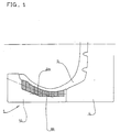
- FIG. 1 there is a radial section showing a mold of the so-called sector type, in which a lateral shell 1 and the sector 4 are seen.
- the shell 1 is characterized by a stack of sheets, and therefore does not have, radial section view, the usual massive appearance.
- Said sheets constitute the lamelliform element used.
- the thickness of said lamelliform elements is between 0.1 and 5 mm.
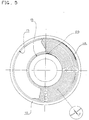
- FIG. 2 represents a stage of manufacture, which will be designated by "obtaining the crude”.
- the shell has a solid support 10, in which a flat face 11 has been machined respectively, then a frustoconical face 12 and finally two cylindrical faces 13.
- These different faces define a housing inside which a sheet metal is wound in a spiral. in the form of a band designated by the reference 20.
- the lateral faces 22 and 23 of the band 20 are contiguous with the adjacent lateral faces.
- it is necessary to use a strip of variable thickness 28 see FIG. 3
- the edge 21 of the strip 20 on the side opposite to the support 10 reproduces the shape of the bottom of the housing machined on the support 10.
- the shape of the bottom of the housing is chosen to be simple to machine while approaching the actual final shape of the sidewall of the tire that has to be molded.
- This is identified by the line 3 in Figure 2. All the turns formed by the band 20 must overlap this line 3. From preferably, the turns are immobilized on the support 10 by making holes as indicated in FIG. 2 and by inserting one or more pins 6.
- the following operation consists in machining the laminated assembly thus produced to the exact shape of the molding shell , according to the line 3 in Figure 2, to obtain a shell 1 like that of Figure 1. This machining operation can be quite similar to the machining operation in the mass.
- this clearance should be less than 0.05 mm, and preferably less than 0.03 mm, taking into account the nature of the rubber mixtures used for the sidewalls.
- the lamelliform element has undergone a knurling operation, before being assembled to constitute the molding surface.
- a cylindrical roller whose surface has sharp transverse ribs, one presses on said strip (or more generally on said lamelliform element), to mark at least one lateral face of transverse grooves starting from said edge to the edge of said lateral faces opposite to said edge, so as to form preferred paths for venting.
- the pressure exerted on the surface of the lamellate element is adjusted so that the grooves have a depth of the order of 0.01 mm.
- the air evacuation paths are thus much less sensitive to fouling and the venting keeps all their efficiency after a very large number of vulcanization cycles.
- the housing of the support 10 may not have a conical portion.
- the lamelliform elements could be hoops of different diameters, the edges of which form a network of concentric figures.
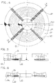
- a spiral winding can be obtained in a different way, as explained below in support of FIGS. 4 to 6 which illustrate an assembly produced without separate support. Then an assembly as well constituted could also be housed in a support as described in Figures 1 and 2.
- a strip 20 is wound with contiguous turns as in the first variant.
- the winding is completed by covering it with a hoop 26, the ends of which are also welded together with radial offset.
- the support can be provided with air evacuation paths arranged on its face receiving said elements by their edge opposite to the molding edge: it is for example a network of grooves leading to said holes.
- the assembly of lamelliform elements itself can be done somewhat differently. It goes without saying that a small number of strips 20 can be used instead of just one. Said strip 20 can be wound with controlled axial offset from one turn to another, to define, by successive increments, a molding surface corresponding to the shape of the sidewall of the tire to be molded directly, without requiring finishing by machining (of course not taking the markings into account).
- the lamelliform elements could be arranged radially and not in spirals or in concentric rings, possibly in several layers each forming a crown. It is possible to promote the passage of air between adjacent lamellate elements by using elements whose faces in contact with one another are striated. It will be understood that the concept proposed by the invention aims to obtain a laminated structure for arranging small interstices oriented perpendicular to the molding surface.
Landscapes
- Engineering & Computer Science (AREA)
- Mechanical Engineering (AREA)
- Moulds For Moulding Plastics Or The Like (AREA)
- Heating, Cooling, Or Curing Plastics Or The Like In General (AREA)
- Tyre Moulding (AREA)
Applications Claiming Priority (2)
| Application Number | Priority Date | Filing Date | Title |
|---|---|---|---|
| FR9309799A FR2708516A1 (fr) | 1993-08-06 | 1993-08-06 | Moule pour pneumatique et procédé de moulage de pneumatique. |
| FR9309799 | 1993-08-06 |
Publications (3)
| Publication Number | Publication Date |
|---|---|
| EP0637504A2 true EP0637504A2 (de) | 1995-02-08 |
| EP0637504A3 EP0637504A3 (de) | 1995-07-19 |
| EP0637504B1 EP0637504B1 (de) | 1998-07-22 |
Family
ID=9450073
Family Applications (1)
| Application Number | Title | Priority Date | Filing Date |
|---|---|---|---|
| EP94110865A Expired - Lifetime EP0637504B1 (de) | 1993-08-06 | 1994-07-13 | Reifenform und Verfahren zum Formen von Reifen |
Country Status (11)
| Country | Link |
|---|---|
| US (1) | US5798076A (de) |
| EP (1) | EP0637504B1 (de) |
| JP (1) | JP3608174B2 (de) |
| KR (1) | KR100322322B1 (de) |
| CN (1) | CN1048450C (de) |
| AT (1) | ATE168620T1 (de) |
| BR (1) | BR9402977A (de) |
| CA (1) | CA2128290A1 (de) |
| DE (1) | DE69411822T2 (de) |
| FR (1) | FR2708516A1 (de) |
| PL (1) | PL174567B1 (de) |
Families Citing this family (23)
| Publication number | Priority date | Publication date | Assignee | Title |
|---|---|---|---|---|
| FR2759626A1 (fr) * | 1997-02-19 | 1998-08-21 | Sedepro | Moule pour pneus |
| US5939002A (en) * | 1997-04-16 | 1999-08-17 | Michelin Recherche Et Technique S.A. | Apparatus and process for changing a sidewall insert of a tire mold |
| US6830722B2 (en) * | 2000-08-04 | 2004-12-14 | Bridgestone Corporation | Method of manufacturing pneumatic tire and vulcanizing metal mold used for the method |
| JP2002166424A (ja) * | 2000-11-29 | 2002-06-11 | Bridgestone Corp | 空気入りタイヤの加硫方法およびそれに用いる金型 |
| US6592807B2 (en) | 2001-05-24 | 2003-07-15 | The Goodyear Tire And Rubber Company | Method of making a porous tire tread mold |
| FR2839003A1 (fr) * | 2002-04-29 | 2003-10-31 | Michelin Soc Tech | Moule pour pneus |
| ES2565164T3 (es) * | 2002-07-01 | 2016-03-31 | Kabushiki Kaisha Bridgestone | Método de fabricación de un molde laminado |
| AU2003302931A1 (en) * | 2002-12-07 | 2004-06-30 | Cooper Technology Services, Llc | Annular venting of tire tread molds |
| KR100499866B1 (ko) * | 2002-12-18 | 2005-07-07 | 한국과학기술원 | 요철모양의 금형을 이용한 mcp 제작 방법 및 장치 |
| DE10308152A1 (de) * | 2003-02-26 | 2004-09-09 | Continental Aktiengesellschaft | Vulkanisierform für Fahrzeugreifen |
| JP4295642B2 (ja) * | 2004-02-27 | 2009-07-15 | 株式会社ブリヂストン | 積層モールドの製造方法 |
| JP2006069174A (ja) * | 2004-09-06 | 2006-03-16 | Juken Fine Tool:Kk | プラスチックフィルタ用金型 |
| JP2007144997A (ja) * | 2005-11-04 | 2007-06-14 | Sumitomo Rubber Ind Ltd | タイヤ用モールドの製造方法 |
| US7530803B2 (en) * | 2007-05-08 | 2009-05-12 | Bridgestone Firestone North American Tire, Llc | Insert for a tire mold vent |
| JP5265148B2 (ja) * | 2007-07-20 | 2013-08-14 | 住友ゴム工業株式会社 | タイヤ用モールドの製造方法 |
| FR2943577B1 (fr) * | 2009-03-30 | 2016-01-01 | Saint Gobain | Procede de moulage d' une piece en matiere plastique avec une piece rapportee maintenue par aspiration, dispositif de moulage et utilisation |
| JP5475437B2 (ja) * | 2009-12-28 | 2014-04-16 | 住友ゴム工業株式会社 | タイヤ用モールド |
| JP5039810B2 (ja) * | 2010-05-18 | 2012-10-03 | 東洋ゴム工業株式会社 | タイヤモールド及び空気入りタイヤの製造方法 |
| JP5117541B2 (ja) * | 2010-06-23 | 2013-01-16 | 住友ゴム工業株式会社 | タイヤ用モールド |
| JP5417493B2 (ja) * | 2012-07-09 | 2014-02-12 | 住友ゴム工業株式会社 | タイヤ用モールド |
| DE102016201063B4 (de) | 2016-01-26 | 2024-07-04 | Continental Reifen Deutschland Gmbh | Verfahren und Vulkanisierform zur Herstellung eines Fahrzeug-Luftreifens |
| JP7189656B2 (ja) * | 2017-02-08 | 2022-12-14 | 住友ゴム工業株式会社 | ゴム押出し装置及びゴム押出し方法 |
| KR102221397B1 (ko) | 2019-09-17 | 2021-03-03 | 넥센타이어 주식회사 | 메인 그루브 성형장치 |
Citations (10)
| Publication number | Priority date | Publication date | Assignee | Title |
|---|---|---|---|---|
| DE343212C (de) * | ||||
| US2297017A (en) * | 1939-05-10 | 1942-09-29 | Max C Overman | Tire mold structure |
| US2679172A (en) * | 1951-03-16 | 1954-05-25 | Walton S Clevenger | Laminated die form and method of producing same |
| US2754546A (en) * | 1951-11-13 | 1956-07-17 | Firestone Tire & Rubber Co | Mold |
| DE2210099A1 (de) * | 1972-03-02 | 1973-09-06 | Dunlop Ag | Verfahren und vorrichtung zur ausformung von gegenstaenden aus waermehaertenden werkstoffen, insbesondere von fahrzeugluftreifen |
| JPS51119776A (en) * | 1975-04-14 | 1976-10-20 | Bridgestone Tire Co Ltd | Metal mold for vulcanizing tire |
| US4058422A (en) * | 1976-09-20 | 1977-11-15 | Victor E. Buehrle | Apparatus for bonding treads to tires |
| US4691431A (en) * | 1984-10-31 | 1987-09-08 | Sumitomo Rubber Industries, Ltd. | Method of making a metal mold for tire vulcanization |
| US5186952A (en) * | 1991-11-20 | 1993-02-16 | Cheng Shin Rubber Ind., Co., Ltd. | Mold for manufacturing tires |
| EP0569909A1 (de) * | 1992-05-13 | 1993-11-18 | Sedepro | Reifenform und Verfahren zum Formen eines Reifens |
Family Cites Families (3)
| Publication number | Priority date | Publication date | Assignee | Title |
|---|---|---|---|---|
| JPS61164806A (ja) * | 1985-01-18 | 1986-07-25 | Bridgestone Corp | モ−ルド |
| IT1240295B (it) * | 1990-04-13 | 1993-12-07 | Pirelli | Stampo e metodo per la vulcanizzazione di pneumatici e metodo per fabbricare stampi |
| DE69301281T2 (de) * | 1992-07-02 | 1996-05-30 | Michelin & Cie | Reifenform, Verfahren zu deren Herstellung und Reifenformverfahren mit Hilfe einer solchen Form |
-
1993
- 1993-08-06 FR FR9309799A patent/FR2708516A1/fr active Pending
-
1994
- 1994-07-13 AT AT94110865T patent/ATE168620T1/de not_active IP Right Cessation
- 1994-07-13 EP EP94110865A patent/EP0637504B1/de not_active Expired - Lifetime
- 1994-07-13 DE DE69411822T patent/DE69411822T2/de not_active Expired - Fee Related
- 1994-07-18 CA CA002128290A patent/CA2128290A1/fr not_active Abandoned
- 1994-07-27 CN CN94107963A patent/CN1048450C/zh not_active Expired - Fee Related
- 1994-07-28 BR BR9402977A patent/BR9402977A/pt not_active IP Right Cessation
- 1994-08-01 KR KR1019940018962A patent/KR100322322B1/ko not_active IP Right Cessation
- 1994-08-05 PL PL94304579A patent/PL174567B1/pl unknown
- 1994-08-08 JP JP20603794A patent/JP3608174B2/ja not_active Expired - Fee Related
-
1996
- 1996-06-24 US US08/667,635 patent/US5798076A/en not_active Expired - Fee Related
Patent Citations (10)
| Publication number | Priority date | Publication date | Assignee | Title |
|---|---|---|---|---|
| DE343212C (de) * | ||||
| US2297017A (en) * | 1939-05-10 | 1942-09-29 | Max C Overman | Tire mold structure |
| US2679172A (en) * | 1951-03-16 | 1954-05-25 | Walton S Clevenger | Laminated die form and method of producing same |
| US2754546A (en) * | 1951-11-13 | 1956-07-17 | Firestone Tire & Rubber Co | Mold |
| DE2210099A1 (de) * | 1972-03-02 | 1973-09-06 | Dunlop Ag | Verfahren und vorrichtung zur ausformung von gegenstaenden aus waermehaertenden werkstoffen, insbesondere von fahrzeugluftreifen |
| JPS51119776A (en) * | 1975-04-14 | 1976-10-20 | Bridgestone Tire Co Ltd | Metal mold for vulcanizing tire |
| US4058422A (en) * | 1976-09-20 | 1977-11-15 | Victor E. Buehrle | Apparatus for bonding treads to tires |
| US4691431A (en) * | 1984-10-31 | 1987-09-08 | Sumitomo Rubber Industries, Ltd. | Method of making a metal mold for tire vulcanization |
| US5186952A (en) * | 1991-11-20 | 1993-02-16 | Cheng Shin Rubber Ind., Co., Ltd. | Mold for manufacturing tires |
| EP0569909A1 (de) * | 1992-05-13 | 1993-11-18 | Sedepro | Reifenform und Verfahren zum Formen eines Reifens |
Non-Patent Citations (1)
| Title |
|---|
| DATABASE WPI Week 7649, Derwent Publications Ltd., London, GB; AN 76-91423X & JP-A-51 119 776 (BRIDGESTONE TIRE K. K.) 21 October 1976 * |
Also Published As
| Publication number | Publication date |
|---|---|
| FR2708516A1 (fr) | 1995-02-10 |
| US5798076A (en) | 1998-08-25 |
| PL174567B1 (pl) | 1998-08-31 |
| PL304579A1 (en) | 1995-02-20 |
| ATE168620T1 (de) | 1998-08-15 |
| JP3608174B2 (ja) | 2005-01-05 |
| KR100322322B1 (ko) | 2002-05-13 |
| EP0637504B1 (de) | 1998-07-22 |
| BR9402977A (pt) | 1995-06-20 |
| DE69411822T2 (de) | 1999-01-14 |
| KR950005488A (ko) | 1995-03-20 |
| CN1102376A (zh) | 1995-05-10 |
| CN1048450C (zh) | 2000-01-19 |
| DE69411822D1 (de) | 1998-08-27 |
| JPH0760863A (ja) | 1995-03-07 |
| CA2128290A1 (fr) | 1995-02-07 |
| EP0637504A3 (de) | 1995-07-19 |
Similar Documents
| Publication | Publication Date | Title |
|---|---|---|
| EP0637504B1 (de) | Reifenform und Verfahren zum Formen von Reifen | |
| EP0653293B1 (de) | Reifenform und Verfahren zum Formen eines Reifens | |
| CA2291652C (fr) | Sculpture et moule pour bande de roulement de pneumatique | |
| EP0665098B1 (de) | Luftreifen | |
| EP1232852B1 (de) | Formwerkzeug und Verfahren zum Formen einer Reifenlauffläche | |
| EP1918087B1 (de) | Form für die Vulkanisierung eines Reifens und Verfahren zur Vulkanisierung eines Reifenrohlings | |
| EP0707934B1 (de) | Entlüftung von Formen | |
| EP2072287B1 (de) | Reifen, Form für die Vulkanisierung dieses Reifens, Herstellungsverfahren dieser Form und Matrize der Form | |
| EP3752349B1 (de) | Aushärtemembran für einen reifen und verfahren zu ihrer herstellung | |
| EP1504882A2 (de) | Verfahren zur Herstellung eines mit mindestens einem Einsatz versehenen Luftreifens | |
| FR2948894A1 (fr) | Procede de surmoulage, et moule pour sa mise en oeuvre | |
| FR2934967A1 (fr) | Pneumatique sans chambre a air ayant une gomme interieure fendue, et procede pour sa fabrication | |
| EP1000728B1 (de) | Herstellung eines Stützkörpers | |
| FR2954222A1 (fr) | Bande de roulement pour pneumatique | |
| EP3980258B1 (de) | Pneumatisches härtungsverfahren unter verwendung einer härtungsmembran mit drei in zunehmender tiefe angeordneten abflussbereichen | |
| EP1595673B1 (de) | Method of manufacturing a tyre tread | |
| EP4058279B1 (de) | Mit einer drainagestruktur ausgerüstete reifenhärtemembran | |
| EP3898279A1 (de) | Lauffläche mit verborgenen vertiefungen und nuten | |
| EP3787865B1 (de) | Formteil mit luftaustrittsschlitz und mikroformbereich | |
| WO2021181036A1 (fr) | Élément de garniture de moule de cuisson pour pneumatique comprenant des lamelles | |
| WO2021123634A1 (fr) | Moule de cuisson pour pneumatiques muni d'un dispositif d'eventation et procede de cuisson associe | |
| FR2881680A1 (fr) | Methode de fabrication d'une bande de roulement pour pneumatique |
Legal Events
| Date | Code | Title | Description |
|---|---|---|---|
| PUAI | Public reference made under article 153(3) epc to a published international application that has entered the european phase |
Free format text: ORIGINAL CODE: 0009012 |
|
| 17P | Request for examination filed |
Effective date: 19940713 |
|
| AK | Designated contracting states |
Kind code of ref document: A2 Designated state(s): AT BE CH DE ES FR GB IT LI LU SE |
|
| PUAL | Search report despatched |
Free format text: ORIGINAL CODE: 0009013 |
|
| AK | Designated contracting states |
Kind code of ref document: A3 Designated state(s): AT BE CH DE ES FR GB IT LI LU SE |
|
| 17Q | First examination report despatched |
Effective date: 19970114 |
|
| GRAG | Despatch of communication of intention to grant |
Free format text: ORIGINAL CODE: EPIDOS AGRA |
|
| GRAG | Despatch of communication of intention to grant |
Free format text: ORIGINAL CODE: EPIDOS AGRA |
|
| GRAH | Despatch of communication of intention to grant a patent |
Free format text: ORIGINAL CODE: EPIDOS IGRA |
|
| GRAH | Despatch of communication of intention to grant a patent |
Free format text: ORIGINAL CODE: EPIDOS IGRA |
|
| GRAA | (expected) grant |
Free format text: ORIGINAL CODE: 0009210 |
|
| AK | Designated contracting states |
Kind code of ref document: B1 Designated state(s): AT BE CH DE ES FR GB IT LI LU SE |
|
| PG25 | Lapsed in a contracting state [announced via postgrant information from national office to epo] |
Ref country code: IT Free format text: LAPSE BECAUSE OF FAILURE TO SUBMIT A TRANSLATION OF THE DESCRIPTION OR TO PAY THE FEE WITHIN THE PRE;WARNING: LAPSES OF ITALIAN PATENTS WITH EFFECTIVE DATE BEFORE 2007 MAY HAVE OCCURRED AT ANY TIME BEFORE 2007. THE CORRECT EFFECTIVE DATE MAY BE DIFFERENT FROM THE ONE RECORDED.SCRIBED TIME-LIMIT Effective date: 19980722 Ref country code: ES Free format text: THE PATENT HAS BEEN ANNULLED BY A DECISION OF A NATIONAL AUTHORITY Effective date: 19980722 Ref country code: AT Free format text: LAPSE BECAUSE OF FAILURE TO SUBMIT A TRANSLATION OF THE DESCRIPTION OR TO PAY THE FEE WITHIN THE PRESCRIBED TIME-LIMIT Effective date: 19980722 |
|
| REF | Corresponds to: |
Ref document number: 168620 Country of ref document: AT Date of ref document: 19980815 Kind code of ref document: T |
|
| REG | Reference to a national code |
Ref country code: CH Ref legal event code: EP |
|
| REF | Corresponds to: |
Ref document number: 69411822 Country of ref document: DE Date of ref document: 19980827 |
|
| PG25 | Lapsed in a contracting state [announced via postgrant information from national office to epo] |
Ref country code: SE Free format text: LAPSE BECAUSE OF FAILURE TO SUBMIT A TRANSLATION OF THE DESCRIPTION OR TO PAY THE FEE WITHIN THE PRESCRIBED TIME-LIMIT Effective date: 19981022 |
|
| GBT | Gb: translation of ep patent filed (gb section 77(6)(a)/1977) |
Effective date: 19981015 |
|
| PLBE | No opposition filed within time limit |
Free format text: ORIGINAL CODE: 0009261 |
|
| STAA | Information on the status of an ep patent application or granted ep patent |
Free format text: STATUS: NO OPPOSITION FILED WITHIN TIME LIMIT |
|
| PG25 | Lapsed in a contracting state [announced via postgrant information from national office to epo] |
Ref country code: LU Free format text: LAPSE BECAUSE OF NON-PAYMENT OF DUE FEES Effective date: 19990713 |
|
| 26N | No opposition filed | ||
| PG25 | Lapsed in a contracting state [announced via postgrant information from national office to epo] |
Ref country code: LI Free format text: LAPSE BECAUSE OF NON-PAYMENT OF DUE FEES Effective date: 19990731 Ref country code: CH Free format text: LAPSE BECAUSE OF NON-PAYMENT OF DUE FEES Effective date: 19990731 Ref country code: BE Free format text: LAPSE BECAUSE OF NON-PAYMENT OF DUE FEES Effective date: 19990731 |
|
| BERE | Be: lapsed |
Owner name: SEDEPRO Effective date: 19990731 |
|
| REG | Reference to a national code |
Ref country code: CH Ref legal event code: PL |
|
| REG | Reference to a national code |
Ref country code: GB Ref legal event code: IF02 |
|
| PGFP | Annual fee paid to national office [announced via postgrant information from national office to epo] |
Ref country code: GB Payment date: 20050704 Year of fee payment: 12 |
|
| PG25 | Lapsed in a contracting state [announced via postgrant information from national office to epo] |
Ref country code: GB Free format text: LAPSE BECAUSE OF NON-PAYMENT OF DUE FEES Effective date: 20060713 |
|
| REG | Reference to a national code |
Ref country code: FR Ref legal event code: TP |
|
| GBPC | Gb: european patent ceased through non-payment of renewal fee |
Effective date: 20060713 |
|
| PGFP | Annual fee paid to national office [announced via postgrant information from national office to epo] |
Ref country code: DE Payment date: 20080722 Year of fee payment: 15 |
|
| PGFP | Annual fee paid to national office [announced via postgrant information from national office to epo] |
Ref country code: FR Payment date: 20080715 Year of fee payment: 15 |
|
| REG | Reference to a national code |
Ref country code: FR Ref legal event code: ST Effective date: 20100331 |
|
| PG25 | Lapsed in a contracting state [announced via postgrant information from national office to epo] |
Ref country code: FR Free format text: LAPSE BECAUSE OF NON-PAYMENT OF DUE FEES Effective date: 20090731 |
|
| PG25 | Lapsed in a contracting state [announced via postgrant information from national office to epo] |
Ref country code: DE Free format text: LAPSE BECAUSE OF NON-PAYMENT OF DUE FEES Effective date: 20100202 |