EP0637497A1 - Kunststoffschweissgerät - Google Patents
Kunststoffschweissgerät Download PDFInfo
- Publication number
- EP0637497A1 EP0637497A1 EP94106289A EP94106289A EP0637497A1 EP 0637497 A1 EP0637497 A1 EP 0637497A1 EP 94106289 A EP94106289 A EP 94106289A EP 94106289 A EP94106289 A EP 94106289A EP 0637497 A1 EP0637497 A1 EP 0637497A1
- Authority
- EP
- European Patent Office
- Prior art keywords
- knife
- rotation
- conveyor
- conveying
- welding device
- Prior art date
- Legal status (The legal status is an assumption and is not a legal conclusion. Google has not performed a legal analysis and makes no representation as to the accuracy of the status listed.)
- Granted
Links
- 239000012815 thermoplastic material Substances 0.000 title abstract 2
- 238000005520 cutting process Methods 0.000 claims abstract description 25
- 239000004033 plastic Substances 0.000 claims description 41
- 238000004023 plastic welding Methods 0.000 claims description 27
- 239000000463 material Substances 0.000 claims description 10
- 230000033001 locomotion Effects 0.000 claims description 2
- 229920000642 polymer Polymers 0.000 abstract 1
- 239000002861 polymer material Substances 0.000 abstract 1
- 238000003466 welding Methods 0.000 description 6
- 238000010438 heat treatment Methods 0.000 description 3
- 210000003746 feather Anatomy 0.000 description 2
- 238000000034 method Methods 0.000 description 2
- 230000008878 coupling Effects 0.000 description 1
- 238000010168 coupling process Methods 0.000 description 1
- 238000005859 coupling reaction Methods 0.000 description 1
- 230000000694 effects Effects 0.000 description 1
- 238000005516 engineering process Methods 0.000 description 1
- 238000002474 experimental method Methods 0.000 description 1
- 230000010006 flight Effects 0.000 description 1
- 238000004519 manufacturing process Methods 0.000 description 1
- 239000002985 plastic film Substances 0.000 description 1
- 238000000926 separation method Methods 0.000 description 1
Images


Classifications
-
- B—PERFORMING OPERATIONS; TRANSPORTING
- B29—WORKING OF PLASTICS; WORKING OF SUBSTANCES IN A PLASTIC STATE IN GENERAL
- B29C—SHAPING OR JOINING OF PLASTICS; SHAPING OF MATERIAL IN A PLASTIC STATE, NOT OTHERWISE PROVIDED FOR; AFTER-TREATMENT OF THE SHAPED PRODUCTS, e.g. REPAIRING
- B29C65/00—Joining or sealing of preformed parts, e.g. welding of plastics materials; Apparatus therefor
- B29C65/02—Joining or sealing of preformed parts, e.g. welding of plastics materials; Apparatus therefor by heating, with or without pressure
- B29C65/40—Applying molten plastics, e.g. hot melt
-
- B—PERFORMING OPERATIONS; TRANSPORTING
- B26—HAND CUTTING TOOLS; CUTTING; SEVERING
- B26D—CUTTING; DETAILS COMMON TO MACHINES FOR PERFORATING, PUNCHING, CUTTING-OUT, STAMPING-OUT OR SEVERING
- B26D1/00—Cutting through work characterised by the nature or movement of the cutting member or particular materials not otherwise provided for; Apparatus or machines therefor; Cutting members therefor
- B26D1/0006—Cutting members therefor
-
- B—PERFORMING OPERATIONS; TRANSPORTING
- B29—WORKING OF PLASTICS; WORKING OF SUBSTANCES IN A PLASTIC STATE IN GENERAL
- B29C—SHAPING OR JOINING OF PLASTICS; SHAPING OF MATERIAL IN A PLASTIC STATE, NOT OTHERWISE PROVIDED FOR; AFTER-TREATMENT OF THE SHAPED PRODUCTS, e.g. REPAIRING
- B29C48/00—Extrusion moulding, i.e. expressing the moulding material through a die or nozzle which imparts the desired form; Apparatus therefor
- B29C48/02—Small extruding apparatus, e.g. handheld, toy or laboratory extruders
-
- B—PERFORMING OPERATIONS; TRANSPORTING
- B29—WORKING OF PLASTICS; WORKING OF SUBSTANCES IN A PLASTIC STATE IN GENERAL
- B29C—SHAPING OR JOINING OF PLASTICS; SHAPING OF MATERIAL IN A PLASTIC STATE, NOT OTHERWISE PROVIDED FOR; AFTER-TREATMENT OF THE SHAPED PRODUCTS, e.g. REPAIRING
- B29C48/00—Extrusion moulding, i.e. expressing the moulding material through a die or nozzle which imparts the desired form; Apparatus therefor
- B29C48/25—Component parts, details or accessories; Auxiliary operations
- B29C48/285—Feeding the extrusion material to the extruder
- B29C48/288—Feeding the extrusion material to the extruder in solid form, e.g. powder or granules
- B29C48/2888—Feeding the extrusion material to the extruder in solid form, e.g. powder or granules in thread form or in strip form, e.g. rubber strips
-
- B—PERFORMING OPERATIONS; TRANSPORTING
- B29—WORKING OF PLASTICS; WORKING OF SUBSTANCES IN A PLASTIC STATE IN GENERAL
- B29C—SHAPING OR JOINING OF PLASTICS; SHAPING OF MATERIAL IN A PLASTIC STATE, NOT OTHERWISE PROVIDED FOR; AFTER-TREATMENT OF THE SHAPED PRODUCTS, e.g. REPAIRING
- B29C66/00—General aspects of processes or apparatus for joining preformed parts
- B29C66/80—General aspects of machine operations or constructions and parts thereof
- B29C66/84—Specific machine types or machines suitable for specific applications
- B29C66/861—Hand-held tools
-
- B—PERFORMING OPERATIONS; TRANSPORTING
- B26—HAND CUTTING TOOLS; CUTTING; SEVERING
- B26D—CUTTING; DETAILS COMMON TO MACHINES FOR PERFORATING, PUNCHING, CUTTING-OUT, STAMPING-OUT OR SEVERING
- B26D1/00—Cutting through work characterised by the nature or movement of the cutting member or particular materials not otherwise provided for; Apparatus or machines therefor; Cutting members therefor
- B26D1/0006—Cutting members therefor
- B26D2001/0033—Cutting members therefor assembled from multiple blades
-
- B—PERFORMING OPERATIONS; TRANSPORTING
- B26—HAND CUTTING TOOLS; CUTTING; SEVERING
- B26D—CUTTING; DETAILS COMMON TO MACHINES FOR PERFORATING, PUNCHING, CUTTING-OUT, STAMPING-OUT OR SEVERING
- B26D1/00—Cutting through work characterised by the nature or movement of the cutting member or particular materials not otherwise provided for; Apparatus or machines therefor; Cutting members therefor
- B26D1/0006—Cutting members therefor
- B26D2001/0046—Cutting members therefor rotating continuously about an axis perpendicular to the edge
-
- B—PERFORMING OPERATIONS; TRANSPORTING
- B26—HAND CUTTING TOOLS; CUTTING; SEVERING
- B26D—CUTTING; DETAILS COMMON TO MACHINES FOR PERFORATING, PUNCHING, CUTTING-OUT, STAMPING-OUT OR SEVERING
- B26D1/00—Cutting through work characterised by the nature or movement of the cutting member or particular materials not otherwise provided for; Apparatus or machines therefor; Cutting members therefor
- B26D1/0006—Cutting members therefor
- B26D2001/006—Cutting members therefor the cutting blade having a special shape, e.g. a special outline, serrations
-
- B—PERFORMING OPERATIONS; TRANSPORTING
- B29—WORKING OF PLASTICS; WORKING OF SUBSTANCES IN A PLASTIC STATE IN GENERAL
- B29C—SHAPING OR JOINING OF PLASTICS; SHAPING OF MATERIAL IN A PLASTIC STATE, NOT OTHERWISE PROVIDED FOR; AFTER-TREATMENT OF THE SHAPED PRODUCTS, e.g. REPAIRING
- B29C2791/00—Shaping characteristics in general
-
- B—PERFORMING OPERATIONS; TRANSPORTING
- B29—WORKING OF PLASTICS; WORKING OF SUBSTANCES IN A PLASTIC STATE IN GENERAL
- B29C—SHAPING OR JOINING OF PLASTICS; SHAPING OF MATERIAL IN A PLASTIC STATE, NOT OTHERWISE PROVIDED FOR; AFTER-TREATMENT OF THE SHAPED PRODUCTS, e.g. REPAIRING
- B29C48/00—Extrusion moulding, i.e. expressing the moulding material through a die or nozzle which imparts the desired form; Apparatus therefor
- B29C48/03—Extrusion moulding, i.e. expressing the moulding material through a die or nozzle which imparts the desired form; Apparatus therefor characterised by the shape of the extruded material at extrusion
Definitions
- the invention relates to a plastic welding device with at least one conveyor channel and a conveyor device assigned to it for a plastic strand, the conveyor channel opening via an opening into a comminution device which has a knife element rotatable about a knife axis of rotation with at least one knife having a cutting edge, and in which Shredding device connect a transport and a plasticizing device for plasticizing and for ejecting the shredded plastic material.
- Such plastic welding devices are used for welding plastic sheets or the like. They essentially consist of a hand drill that serves as a drive and a removable attachment attached to it. In the front attachment, a plastic strand in the form of a plastic wire fed into a conveyor channel - several parallel conveyor channels can also be provided - and a conveyor device are first cut up and then heated in a conveyor device, usually designed as a screw conveyor, and a plasticizing device such that the fragmented plastic material is plastic Condition and is expelled through a mouthpiece as welding material.
- DE-OS 28 23 171 a generic plastic welding device is disclosed.
- the plastic wire is by means of the Conveying device fed to a separate shredding device.
- This comminution device consists of a plurality of knives, which are arranged on the jacket of the screw conveyor in the area on the inlet side and are distributed radially outward and projecting over the circumference. The cutting edges extend parallel to the axis of rotation of the screw conveyor and, when they are rotated - driven by the hand drill - sweep over an opening of the conveying channel in a housing jacket surrounding the comminution device.
- the previously known shredding device causes difficulties in shredding the plastic wire.
- the capacity of the shredding device is necessarily low because there is only one path available for conveying the plastic wire between two knives, which corresponds approximately to the height of the knives.
- the further transport of the shredded plastic material is not sufficiently secured, since the spaces between individual knives have no connection to the screw flights of the transport screw.
- plastic wire is a relatively tough material, when the ends protruding from the opening are knocked off, imperfect separations and canting of the plastic wire occur within the conveying channel, in particular in the region of the opening of the conveying channel. This in turn leads to disruptions in the conveyance of the plastic wire and thus ultimately to the machine downtime, which is particularly important for a welding process that is currently running is disadvantageous.
- DE-OS 28 23 171 a plastic welding device of the type described in DE-OS 28 23 171 has not come onto the market.
- the applicant of DE-OS 28 23 171 has dispensed with the problematic comminution device (DE-PS 32 21 492).
- DE-PS 32 21 492 the plastic wire is routed in pieces to the screw conveyor of the transport device, where it is cut up by the screw itself.
- a conveyor roller which is connected in one piece to the conveyor screw on the input side and has a thread-like profile on its circumference, serves as the conveyor device, with the conveyor channel being guided in a partial section parallel to the axis of rotation of the conveyor roller and open towards it, in such a way that the profile in notch the outer sheath of the plastic wire.
- the proposal has been made in DE-OS 38 25 250 to feed the conveying channel to the conveying device, which is also designed as a profiled conveying roller, in such a way that the plastic wire is at least pre-shredded by the screw-like profiling of the conveying roller.
- the invention is therefore based on the object of designing a plastic welding device in such a way that the output of a homogeneous plasticized strand of plastic is ensured.
- the rotation surface generated by the cutting edge (s) during the rotation of the knife element with its continuation directed towards the knife axis of rotation intersects the knife axis of rotation and that at least one part lying in the region of the opening of the conveying channel or Parts of the rotation surface lying in the region of the openings of the conveying channels are or are designed as counter knives.
- the rotation surface is to be understood as a fictitious surface that is generated from all points of the cutting edge (s) when the knife element is rotated.
- the cutting edge (s) generate a surface of revolution forming a truncated cone by means of a correspondingly inclined arrangement with respect to the knife axis of rotation.
- the surface of rotation is a plane perpendicular to the axis of rotation of the knife, especially since the counter knife or knives are also each formed as planes perpendicular to the axis of rotation of the knife.
- the conveying device has a conveying roller which can be rotated about an axis of rotation of the roller and the conveying channel or conveying channels in the region of the conveying roller in each case run or extend at least over a portion parallel to the axis of rotation of the roller and is open towards the conveying roller or are and that the conveyor roller carries a profile extending into the conveying channel or conveying channels and causing a conveying movement of the plastic strand, for example in the form of at least one helical conveying web or several conveying webs running in multiple courses.
- This known from DE-PS 32 21 492 design of the conveyor allows a particularly compact and slim shape of the plastic welding device.
- the conveying channel or conveying channels merge into a closed section at a distance from the counter knife, which extends to the associated counter knife. This way the plastic strand is in the area enclosed on all sides of the shredding device and therefore guided properly, which results in a clean cut in the shredding device.
- the above-described design can be dispensed with if the cutting edges of the knives are aligned in such a way that they produce an obliquely outwardly directed cutting pressure. In this way it is ensured that even if no closed section is provided, the cutting forces always act against a wall of the conveying channel or conveying channels and a clean cut is thus achieved.
- the solution is technically simpler.
- the knife element is attached to the output end of the conveyor roller. If the transport device has a transport screw that can be rotated about an axis of rotation of the screw, the knife element can also be attached coaxially to the end of the transport screw on the input side.
- the conveying roller and the conveying screw are arranged coaxially to one another and connected to one another in a rotationally fixed manner, the knife element being arranged between the two, in particular clamped.
- Figure (1) partially represents a plastic welding device, namely only the attachment (1) for attachment to a hand drill.
- the attachment (1) has a mounting hole (2) on the right-hand side in this view, into which the drill head of the hand drill can be inserted.
- the receiving bore (2) sits in a multi-step, each cylindrical housing (3).
- the housing (3) has a reduced axial bore (4) following the receiving bore (2), into which a cylindrical insert sleeve (5) is inserted up to an annular shoulder surface (6) which ends the axial bore (4).
- the insert sleeve (5) is fixed in position with the aid of a screw (7) which extends radially through the housing (3) and surrounds the insert sleeve (5).
- the inner surface of the insert sleeve (5) is stepped, i.e. Over the largest area, the inner surface has a larger diameter than in an end area (8) adjacent to the ring shoulder area (6). In the upper area, the insert sleeve (5) runs through an axially extending section of a conveying channel (9).
- the delivery channel (9) bends upward and continues in an inclined bore (2) which penetrates the housing (3).
- a feed roller (11) extends in the insert sleeve (5), the casing of which is surrounded by a screw web (12) which is sawtooth-shaped in cross section.
- the screw web (12) extends to the inner wall of the insert surface (5) and therefore also projects into into the open area of the delivery channel (9).
- the conveyor roller (11) has a bearing section (13) protruding towards the receiving bore (2), which is supported on an axial ball bearing (15) with an annular web (14). This in turn rests on a support ring (16) inserted into the inner wall of the housing (3).
- a drive shaft (17) projects into an axial bore of the conveyor roller (11) and is connected in a rotationally fixed manner to the bearing section (13) of the conveyor roller (11) via a feather key (18).
- the drive shaft (17) has a flange (19), via which it can be connected to the drill head of the hand drill.
- the axial bore (4) in the housing (3) is adjoined by a screw bore (20) narrowed around the ring shoulder surface (6), which is coaxial with the axial bore (4) or the receiving bore (2).
- the screw bore (20) - which is not shown here - merges into a mouthpiece.
- a screw conveyor (21) is arranged in the screw bore (20) and is provided with a screw web (22).
- the screw conveyor (21) has an extension which projects into a bore in the conveyor roller (11) and which has a rotationally fixed connection to the conveyor roller (11) via a feather key (24).
- the transport screw (21) has a support ring web (25) projecting radially outwards.
- a knife element (26) is clamped between the support ring web (25) and the end face of the conveyor roller (11) opposite this.
- the bracing is achieved in that the extension (23) has a threaded bore (27) which is open towards the free end and into which a clamping screw (28) is fitted, the head of which protrudes on an annular web (29) projecting on the inside of the conveyor roller (11) ) supports.
- the knife element (26) has such a radial extent that it covers almost the entire end face of the insert sleeve (5) and in particular the opening of the delivery channel (9).
- the position of the insert sleeve (5) and the axial support of the conveyor roller via the axial ball bearing (15) or the support ring (16) are matched to one another in such a way that the knife element (26) rests approximately on the end face of the insert sleeve (5) there or there is little play between the two.
- the exact design of the knife element (26) results from the figures (2) and (3).
- the knife element (26) has a non-circular central opening (30) with which the knife element (26) sits on a section of the extension (23) adapted to it, so that the two are connected to one another in a rotationally fixed manner.
- the central opening (30) is surrounded by a ring section (31), from which a total of six outward-facing knives - designated by (32) for example - extend.
- the knives (32) each have a cutting edge - designated by (33) for example.
- the cutting edges (33) run radially to the center point or to the knife axis of rotation of the knife element (26).
- the attachment (1) is connected to a hand drill by inserting its drill head into the mounting hole (2) and coupling to the drive shaft (17). Furthermore, a heating device, not shown here, is started, which is attached to the section of the screw bore (20) or the transport screw (21), not shown. A plastic wire is then inserted into the delivery channel (9) via the oblique bore (10).
- the drive shaft (17), the conveyor roller (11), the extension (23) and thus the transport screw (21) and the knife element (26) are set in rotation.
- the direction of rotation is such that the screw web (12) develops a conveying effect in the direction of the screw conveyor (21), i.e. the plastic wire introduced into the conveying channel (9) is transported in the direction of the tubular end section of the conveying channel (9) in that the screw web (12) digs into the sheath of the plastic wire with its tips.
- the plastic wire when it emerges from the conveying channel (9) between two rotating knives (32), is cut cleanly by the knife (32) following in the rotating direction.
- the opening of the delivery channel (9) in the end face of the insert sleeve (5) acts as a counter knife.
- the plastic material which has been dismembered in this way, then passes through an obliquely extending recess (34) in the housing (3) into the region of the transport screw (21) and is then conveyed to the left in the view shown.
- the dismembered parts of the plastic material heat up, the heating in the following heating device, not shown here, being driven to such an extent that the plastic material becomes plastic and converts to a homogeneous, plasticized plastic strand.
- This strand is then continuously ejected from the mouthpiece of the attachment (1) and then forms the welding material for the objects to be welded.
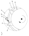
- Figure (4) shows a cross section through another attachment (35) with a view of a knife element (36) in the foreground and an insert sleeve (37) and a conveyor roller (38) in the background.
- the insert sleeve (37) runs downwards open towards the conveyor roller (38), U-shaped delivery channel (39) in which a plastic wire (40) is seated.
- the knife element (36) has radially outwardly protruding knives - designated by way of example with (41) - which have a triangular shape.
- their cutting edges - designated by way of example (42) - do not run radially, but rather obliquely to the radial direction in such a way that the perpendicular to the cutting edges (42) is directed obliquely outwards is.
- a corresponding outward cutting pressure acts on the plastic wire (40) during the cutting process, symbolized by the arrow (A).
- the plastic wire (40) is fully supported in this direction from the inside of the conveyor channel (39).
- the delivery channel (39) need not be designed to be closed at the bottom.
Landscapes
- Engineering & Computer Science (AREA)
- Mechanical Engineering (AREA)
- Life Sciences & Earth Sciences (AREA)
- Forests & Forestry (AREA)
- Health & Medical Sciences (AREA)
- Clinical Laboratory Science (AREA)
- Processing And Handling Of Plastics And Other Materials For Molding In General (AREA)
- Lining Or Joining Of Plastics Or The Like (AREA)
- Separation, Recovery Or Treatment Of Waste Materials Containing Plastics (AREA)
- Crushing And Pulverization Processes (AREA)
- Perforating, Stamping-Out Or Severing By Means Other Than Cutting (AREA)
Abstract
Description
- Die Erfindung betrifft ein Kunststoffschweißgerät mit wenigstens einem Förderkanal und einer diesem zugeordneten Fördereinrichtung für einen Kunststoffstrang, wobei der Förderkanal über eine Öffnung in eine Zerkleinerungseinrichtung mündet, die ein um eine Messerdrehachse rotierbares Messerelement mit wenigstens einem eine Schneidkante aufweisenden Messer hat, und wobei sich an die Zerkleinerungseinrichtung eine Transport- und eine Plastifiziereinrichtung zur Plastifizierung und für den Ausstoß des zerkleinerten Kunststoffmaterials anschließen.
- Solche Kunststoffschweißgeräte werden zum Verschweißen von Kunststoffplatten oder dergleichen verwendet. Sie bestehen im wesentlichen aus einer Handbohrmaschine, die als Antrieb dient, und einem darauf abnehmbar aufgesetzten Vorsatzgerät. In dem Vorsatzgerät wird ein über einen Förderkanal - es können auch mehrere parallele Förderkanäle vorgesehen sein - und eine Fördereinrichtung zugeführter Kunststoffstrang in Form eines Kunststoffdrahtes zunächst zerstückelt und dann in einer meist als Transportschnecke ausgebildeten Transporteinrichtung und einer Plastifiziereinrichtung derart erwärmt, daß das Zerstückelte Kunststoffmaterial einen plastischen Zustand einnimmt und über ein Mundstück als Schweißmaterial ausgestoßen wird.
- In der DE-OS 28 23 171 ist ein gattungsgemäßes Kunststoffschweißgerät offenbart. Bei diesem Kunststoffschweißgerät wird der Kunststoffdraht mittels der Fördereinrichtung einer gesonderten Zerkleinerungseinrichtung zugeführt. Diese Zerkleinerungseinrichtung besteht aus einer Mehrzahl von Messern, die auf dem Mantel der Transportschnecke im eingangsseitigen Bereich radial nach außen vorstehend über den Umfang verteilt angeordnet sind. Dabei erstrecken sich die Schneidkanten parallel zur Drehachse der Transportschnecke und streichen bei ihrer Drehung - angetrieben von der Handbohrmaschine - über eine Öffnung des Förderkanals in einem die Zerkleinerungseinrichtung umgebenden Gehäusemantel.
- Die vorbekannte Zerkleinerungseinrichtung bereitet bei der Zerkleinering des Kunststoffdrahtes Schwierigkeiten. So ist die Kapazität der Zerkleinerungseinrichtung notwendigerweise deshalb gering, weil für die Förderung des Kunststoffdrahtes zwischen zwei Messern nur ein Weg zur Verfügung steht, der in etwa der Höhe der Messer entspricht. Außerdem ist der Weitertransport des zerkleinerten Kunststoffmaterials nicht hinreichend gesichert, da die Zwischenräume zwischen einzelnen Messern keine Verbindung zu den Schneckengängen der Transportschnecke haben.
- Ein wesentlicher Nachteil besteht zudem darin, daß der in die Zerkleinerungseinrichtung eingeförderte Teil des Kunststoffdrahtes nicht sauber abgeschnitten, sondern eher abgschlagen wird. Dies beruht darauf, daß die Schneidkanten bei einer Zerkleinerungseinrichtung dieser Art nicht nahe genug an den umgebenden Gehäusemantel angenähert werden dürfen, um der Transportschnecke hinreichend Spiel für Durchbiegungen zu lassen. Da es sich bei Kunststoffdraht um relativ zähes Material handelt, kommt es beim Abschlagen der aus der Öffnung herausragenden Enden zu unvollkommenen Abtrennungen und Verkantungen des Kunststoffdrahtes innerhalb des Förderkanals, und zwar insbesondere im Bereich der Öffnung des Förderkanals. Dies wiederum führt zu Störungen der Förderung des Kunststoffdrahtes und damit letztendlich zum Gerätestillstand, was für einen gerade laufenden Schweißvorgang besonders nachteilig ist.
- Aus den vorgenannten Gründen ist ein Kunststoffschweißgerät der in der DE-OS 28 23 171 beschriebenen Art nicht auf den Markt gekommen. In einer Weiterentwicklung des Kunststoffschweißgerätes hat die Anmelderin der DE-OS 28 23 171 auf die problematische Zerkleinerungseinrichtung verzichtet (DE-PS 32 21 492). Bei diesem Kunststoffschweißgerät wird der Kunststoffdraht unzerstückelt bis zur Transportschnecke der Transporteinrichtung geführt und dort von der Transportschnecke selbst zerstückelt. Als Fördereinrichtung dient dabei eine einstückig mit der Transportschnecke eingangsseitig verbundene Förderwalze, die auf ihrem Umfang eine gewindeartige Profilierung hat, wobei der Förderkanal in einem Teilabschnitt parallel zur Drehachse der Förderwalze geführt und zu dieser hin offen gestaltet ist, und zwar derart, daß die Profilierung in den Außenmantel des Kunststoffdrahtes einkerben, kann.
- Es hat sich gezeigt, daß auch bei dieser Lösung kein sauberes Abschneiden der über den Förderkanal eingeführten Enden des Kunststoffdrahtes erreichbar ist. Die abgeschnittenen Längen des Kunststoffdrahtes sind sehr ungleichmäßig, was zur Folge hat, daß der aus dem Mundstück des Kunststoffschweißgerätes austretende, plastifizierte Kunststoffstrang inhomogen ist. Dies wiederum beeinträchtigt die Qualität der Schweißnaht.
- Um insoweit eine Verbesserung zu erzielen, ist in der DE-OS 38 25 250 der Vorschlag gemacht worden, den Förderkanal, der ebenfalls als profilierte Förderwalze ausgebildeten Fördereinrichtung so zuzuführen, daß der Kunststoffdraht schon von der schneckenartig ausgebildeten Profilierung der Förderwalze zumindest vorzerkleinert wird.
- Da die Profilierung der Förderwalze sowohl Förder- als auch Schneidfunktion haben muß, kommt es auch hier nicht zu einem sauberen Zerkleinern des Kunststoffdrahtes. Das Problem der Inhomogenität und damit letztendlich der Schweißqualität ist deshalb auch mit dieser Ausbildung eines Kunststoffschweißgerätes nicht befriedigend gelöst.
- Der Erfindung liegt deshalb die Aufgabe zugrunde, ein Kunststoffschweißgerät so zu gestalten, daß der Ausstoß eines homogenen plastifizierten Kunststoffstrangs gewährleistet ist.
- Diese Aufgabe wird erfindungsgemäß dadurch gelöst, daß die von der bzw. den Schneidkante(n) bei der Rotation des Messerelements erzeugte Rotationsfläche mit ihrer auf die Messerdrehachse gerichteten Fortsetzung die Messerdrehachse schneidet und daß zumindest ein im Bereich der Öffnung des Förderkanals liegender Teil bzw. die im Bereich der Öffnungen der Förderkanäle liegenden Teile der Rotationsfläche als Gegenmesser ausgebildet ist bzw. sind. Dabei ist unter Rotationsfläche eine fiktive Fläche zu verstehen, die bei der Verdrehung des Messerelements von allen Punkten der Schneidkante(n) erzeugt wird.
- Mit dieser Lösung wird auf einen Stand der Technik in Form der DE-OS 28 23 171 zurückgegriffen, von dem sich die weitere Entwicklung des Standes der Technik (vgl. DE-PS-32 21 492 und DE-PS 38 35 250) wegen deren offensichtlicher Nachteile schon gelöst hatte. Dabei ist die Zerkleinerungseinrichtung jetzt so gestaltet worden, daß das Messerelement durch einfache axiale Einstellung beliebig nahe an die Öffnung des Förderkanals bzw. die Öffnungen der Förderkanäle herangeführt werden kann, so daß die Öffnung bzw. die Öffnungen als Gegenmesser wirkt bzw. wirken, Messer und Gegenmesser also einen sauberen Schneidvorgang wie bei einer Schere bewirken. Versuche haben gezeigt, daß sich der Kunststoffdraht trotz seiner zähen Konsistenz in immer gleich große Einzelstücke zerkleinern läßt, ohne daß es dabei zu Schwierigkeiten bei der Zufuhr des Kunststoffdrahtes im Förderkanal kommt. Dies wiederum hat eine wesentliche Verbesserung der Homogenität und damit letztendlich der Schweißqualität zur Folge. Durch den Zerkleinerungsvorgang bewirkte Betriebsunterbrechungen treten praktisch nicht mehr auf.
- Die konkrete Ausgestaltung des Grundgedankens der Erfindung kann in verschiedener Weise erfolgen. So ist es denkbar, daß die Schneidkante(n) durch entsprechend geneigte Anordnung zur Messerdrehachse eine einen Kegelstumpfmantel bildende Rotationsfläche erzeugen. Herstellungstechnisch einfacher ist jedoch eine Ausbildung, bei der die Rotationsfläche eine senkrecht zur Messerdrehachse stehende Ebene ist, zumal dann das bzw. die Gegenmesser jeweils ebenfalls als zur Messerdrehachse senkrecht stehende Ebenen ausgebildet sind. Um eine hohe Zerkleinerungsleistung zu erreichen, empfiehlt es sich dabei, das Messerelement mit einer Mehrzahl von Messern auszustatten, beispielsweise mit sich radial erstreckenden Schneidkanten nach Art eines Schneidsterns.
- Nach einem weiteren Merkmal der Erfindung ist vorgesehen, daß die Fördereinrichtung eine um eine Walzendrehachse rotierbare Förderwalze aufweist und der Förderkanal bzw. die Förderkanäle im Bereich der Förderwalze jeweils wenigstens über ein Teilstück parallel zur Walzendrehachse verläuft bzw. verlaufen und zur Förderwalze hin offen ist bzw. sind und daß die Förderwalze eine in den Förderkanal bzw. die Förderkanäle hineinreichende, eine Förderbewegung des Kunststoffstrangs bewirkende Profilierung, beispielsweise in Form wenigstens eines schraubenförmigen Fördersteges oder mehrerer, in mehrgängiger Ausbildung verlaufender Förderstege, trägt. Diese an sich aus der DE-PS 32 21 492 bekannte Ausbildung der Fördereinrichtung läßt eine besonders kompakte und schlanke Formgebung des Kunststoffschweißgerätes zu. Dabei ist es zweckmäßig, daß der Förderkanal bzw. die Förderkanäle jeweils im Abstand zum Gegenmesser wieder in einen geschlossenen Teilabschnitt übergehen, der bis zum zugehörigen Gegenmesser reicht. Auf diese Weise wird der Kunststoffstrang im Bereich der Zerkleinerungseinrichtung allseitig umschlossen und deshalb einwandfrei geführt, was einen sauberen Schnitt in der Zerkleinerungseinrichtung zur Folge hat.
- Auf die vorbeschriebene Ausbildung kann verzichtet werden, wenn die Schneidkanten der Messer derart ausgerichtet sind, daß sie einen schräg nach außen gerichteten Schneiddruck erzeugen. Auf diese Weise ist gesichert, daß auch dann, wenn kein geschlossener Teilabschnitt vorgesehen ist, die Schnittkräfte immer gegen eine Wandung des Förderkanals bzw. der Förderkanäle wirken und damit ein sauberer Schnitt erzielt wird. Die Lösung ist fertigungstechnisch einfacher.
- In weiterer Ausgestaltung der Erfindung ist vorgesehen, daß das Messerelement am ausgangsseitigen Ende der Förderwalze befestigt ist. Sofern die Transporteinrichtung eine um eine Schneckendrehachse rotierbare Transportschnecke aufweist, kann das Messerelement auch koaxial am eingangsseitigen Ende der Transportschnecke angebracht sein. In besonders bevorzugter Ausbildung sind Förderwalze und Transportschnecke koaxial zueinander angeordnet und drehfest miteinander verbunden, wobei das Messerelement zwischen beiden angeordnet, insbesondere eingespannt ist.
- In der Zeichnung ist die Erfindung an Hand eines Ausführungsbeispiels näher veranschaulicht. Es zeigen:
- Figur (1)
- einen teilweisen Längsschnitt durch ein Vorsatzgerät für ein Kunststoffschweißgerät und
- Figur (2)
- eine Draufsicht auf ein Messerelement des Kunststoffschweißgerätes gemäß Figur (1);
- Figur (3)
- eine Seitenansicht des Messerelements gemäß Figur (2) und
- Figur (4)
- eine Draufsicht auf ein weiteres Messerelement.
- Figur (1) stellt teilweise ein Kunststoffschweißgerät dar, und zwar nur das Vorsatzgerät (1) für die Anbringung an einer Handbohrmaschine. Hierzu weist das Vorsatzgerät (1) in dieser Ansicht rechtsseitig eine Aufnahmebohrung (2) auf, in die der Bohrkopf der Handbohrmaschine passend einsetzbar ist. Die Aufnahmebohrung (2) sitzt in einem mehrfach gestuften, jeweils zylindrischen Gehäuse (3).
- Das Gehäuse (3) hat im Anschluß an die Aufnahmebohrung (2) eine reduzierte Axialbohrung (4), in die eine zylindrische Einsatzhülse (5) bis zu einer die Axialbohrung (4) beendenden Ringabsatzfläche (6) eingesetzt ist. Die Einsatzhülse (5) ist mit Hilfe einer sich radial durch das Gehäuse (3) erstreckenden und in die Einsatzhülse (5) einfassenden Schraube (7) lagefixiert. Die Innenfläche der Einsatzhülse (5) ist gestuft, d.h. über den größten Bereich hat die Innenfläche einen größeren Durchmesser als in einem der Ringabsatzfläche (6) benachbarten Endbereich (8). Im oberen Bereich durchzieht die Einsatzhülse (5) ein sich axial erstreckender Teilabschnitt eines Förderkanals (9). Er ist zur Ringabsatzfläche (6) hin gerichtet offen und hat einen solchen Durchmesser, daß er im Endbereich (8) der Einsatzhülse (5) rohrförmig ist, jedoch in dem sich daran in Richtung auf die Aufnahmebohrung (2) anschließenden Teil nach innen hin offen ist. Am Ende des offenen Bereichs biegt der Förderkanal (9) schräg nach oben und setzt sich in einer Schrägbohrung (2) fort, die das Gehäuse (3) durchdringt.
- In der Einsatzhülse (5) erstreckt sind eine Förderwalze (11), deren Mantel mit einem im Querschnitt sägezahnförmigen Schraubensteg (12) umgeben ist. Der Schraubensteg (12) geht bis zur Innenwandung der Einsatzfläche (5) und ragt deshalb auch in den offenen Bereich des Förderkanals (9) hinein. Die Förderwalze (11) hat eine zur Aufnahmebohrung (2) hinausragenden Lagerabschnitt (13), der sich mit einem Ringsteg (14) an einem Axialkugellager (15) abstützt. Dieses wiederum liegt an einem in die Innenwandung des Gehäuses (3) eingesetzten Stützring (16) an.
- In eine Axialbohrung der Förderwalze (11) ragt eine Antriebswelle (17) hinein, die über eine Paßfeder (18) drehfest mit dem Lagerabschnitt (13) der Förderwalze (11) verbunden ist. Die Antriebswelle (17) hat einen Flansch (19), über die sie mit dem Bohrkopf der Handbohrmaschine verbindbar ist.
- An die Axialbohrung (4) im Gehäuse (3) schließt sich eine um die Ringabsatzfläche (6) verengte Schneckenbohrung (20) an, die koaxial zu der Axialbohrung (4) bzw. der Aufnahmebohrung (2) liegt. Die Schneckenbohrung (20) geht - was hier nicht näher dargestellt ist - in ein Mundstück über. In der Schneckenbohrung (20) ist eine Transporschnecke (21) angeordnet, die mit einem Schneckensteg (22) versehen ist. Die Transportschnecke (21) weist einen in eine Bohrung der Förderwalze (11) hineinragende Fortsatz auf, der über eine Paßfeder (24) eine drehfeste Verbindung mit der Förderwalze (11) hat.
- Am eingangsseitigen Ende hat die Transportschnecke (21) einen radial nach außen vorstehenden Stützringsteg (25). Zwischen Stützringsteg (25) und der diesem gegenüberliegenden Stirnfläche der Förderwalze (11) ist ein Messerelement (26) eingespannt. Die Verspannung wird dadurch erreicht, daß der Fortsatz (23) eine zum freien Ende hin offene Gewindebohrung (27) aufweist, in die eine Spannschraube (28) einfaßt, deren Kopf sich auf einem an der Innenseite der Förderwalze (11) vorspringenden Ringsteg (29) abstützt. Durch Anziehen der Spannschraube (28) werden der Fortsatz (23) und damit die Transportschnecke (21) in Richtung auf die Stirnfläche der Förderwalze (11) gezogen und verspannen damit das Messerelement (26) zwischen Stützringsteg (25) und gegenüberliegender Stirnfläche der Förderwalze (11).
- Das Messerelement (26) hat eine solche radiale Erstreckung, daß es nahezu die gesamte Stirnfläche der Einsatzhülse (5) und dabei insbesondere die Öffnung des Förderkanals (9) überstreicht. Dabei sind die Lagefixierung der Einsatzhülse (5) und die axiale Abstützung der Förderwalze über das Axialkugellager (15) bzw. den Stützring (16) so aufeinander abgestimmt, daß das Messerelement (26) in etwa an der dortigen Stirnseite der Einsatzhülse (5) anliegt oder zwischen beiden nur ein geringes Spiel vorhanden ist.
- Die genaue Ausbildung des Messerelements (26) ergibt sich aus den Figuren (2) und (3). Das Messerelement (26) hat eine nicht kreisrunde Mittenöffnung (30), mit der das Messerelement (26) auf einem an diese angepaßten Abschnitt des Fortsatzes (23) sitzt, so daß beide drehfest miteinander verbunden sind. Die Mittenöffnung (30) wird von einem Ringabschnitt (31) umgeben, von dem insgesamt sechs nach außen gerichtete Messer - beispielhaft mit (32) bezeichnet - ausgehen. In der vorgesehenen Drehrichtung weisen die Messer (32) jeweils eine Schneidkante - beispielhaft mit (33) bezeichnet - auf. Die Schneidkanten (33) verlaufen radial zum Mittelpunkt bzw. zur Messerdrehachse des Messerelements (26).
- Für den Betrieb des Kunststoffschweißgerätes wird das Vorsatzgerät (1) an eine Handbohrmaschine durch Einsetzen von deren Bohrkopf in die Aufnahmebohrung (2) und Kupplung mit der Antriebswelle (17) verbunden. Ferner wird eine hier nicht nähre dargestellte Heizeinrichtung in Gang gesetzt, die an dem nicht dargestellten Abschnitt der Schneckenbohrung (20) bzw. der Transportschnecke (21) angebracht ist. Ober die Schrägbohrung (10) wird dann ein Kunststoffdraht in den Förderkanal (9) eingeführt.
- Durch Anschalten der Handbohrmaschine werden die Antriebswelle (17), die Förderwalze (11), der Fortsatz (23) und damit die Transportschnecke (21) sowie das Messerelement (26) in Drehung versetzt. Dabei ist die Drehrichtung so, daß der Schraubensteg (12) eine Förderwirkung in Richtung auf die Transportschnecke (21) entwickelt, d.h. der in den Förderkanal (9) eingeführte Kunststoffdraht wird in Richtung auf den rohrförmigen Endabschnitt des Förderkanals (9) transportiert, indem der Schraubensteg (12) sich mit seinen Spitzen in den Mantel des Kunststoffdrahtes eingräbt.
- Im Bereich des Messerelements (26) wird der Kunststoffdraht, wenn er zwischen zwei umlaufenden Messern (32) aus dem Förderkanal (9) ausgetreten ist, von dem in Umlaufrichtung nachfolgenden Messer (32) sauber abgeschnitten. Dabei wirkt die Öffnung des Förderkanals (9) in der Stirnseite der Einsatzhülse (5) als Gegenmesser. Das so zerstückelte Kunststoffmaterial gelangt dann über eine schräg verlaufende Ausnehmung (34) im Gehäuse (3) in den Bereich der Transportschnecke (21) und wird dann von dieser in der gezeigten Ansicht nach links gefördert. Aufgrund der dabei auftretenden Reibung erwärmen sich die zerstückelten Teile des Kunststoffmaterials, wobei die Erwärmung in der nachfolgenden, hier nicht dargestellten Heizeinrichtung soweit getrieben wird, daß das Kunststoffmaterial plastisch wird und sich zu einem homogenen, plastifizierten Kunststoffstrang umwandelt. Dieser Strang wird dann fortlaufend aus dem Mundstück des Vorsatzgerätes (1) ausgestoßen und bildet dann das Schweißmaterial für die zu verschweißenden Gegenstände.
- Figur (4) stellt einen Querschnitt durch ein anderes Vorsatzgerät (35) mit Blick auf ein Messerelement (36) im Vordergrund sowie eine Einsatzhülse (37) und eine Förderwalze (38) im Hintergrund dar. Dabei durchläuft die Einsatzhülse (37) ein nach unten in Richtung auf die Förderwalze (38) offenen, U-förmigen Förderkanal (39), in dem ein Kunststoffdraht (40) sitzt.
- Das Messerelement (36) hat radial nach außen vorstehende Messer - beispielhaft mit (41) bezeichnet -, welche Dreieckform haben. Deren Schneidkanten - beispielhaft mit (42) bezeichnet - verlaufen im Unterschied zu der Ausführungsform gemäß den Figuren (2) und (3) nicht radial, sondern schräg zur Radialrichtung in der Weise, daß die Senkrechte auf die Schneidkanten (42) schräg nach außen gerichtet ist. Auf diese Weise wirkt beim Schneidvorgang auf den Kunststoffdraht (40) ein entsprechend nach außen gerichteter Schneiddruck, symbolisiert durch den Pfeil (A). Dabei wird der Kunststoffdraht (40) in dieser Richtung voll von der Innenseite des Förderkanals (39) abgestützt. Der Förderkanal (39) braucht in diesem Fall nicht nach unten hin geschlossen ausgebildet sein.
Claims (12)
- Kunststoffschweißgerät mit wenigstens einem Förderkanal und einer diesem zugeordneten Fördereinrichtung für einen Kunststoffstrang, wobei der Förderkanal bzw. die Förderkanäle über jeweils eine Öffnung in eine Zerkleinerungseinrichtung mündet bzw. münden, die ein um eine Messerdrehachse rotierbares Messerelement mit wenigstens einem eine Schneidkante aufweisenden Messer hat, und wobei sich an die Zerkleinerungseinrichtung eine Transport- und eine Plastifiziereinrichtung zur Plastifizierung und für den Ausstoß des Kunststoffmaterials anschließen,
dadurch gekennzeichnet, daß die von der bzw. den Schneidkante(n) (33, 42) bei der Rotation des Messerelements (26, 36) erzeugte Rotationsfläche mit ihrer auf die Messerdrehachse gerichteten Fortsetzung die Messerdrehachse schneidet und daß zumindest ein im Bereich der Öffnung des Förderkanals (9, 39) liegender Teil bzw. die im Bereich der Förderkanäle liegenden Teile der Rotationsfläche als Gegenmesser ausgebildet ist bzw. sind. - Kunststoffschweißgerät nach Anspruch (1),
dadurch gekennzeichnet, daß die Rotationsfläche eine senkrecht zur Messerdrehachse stehende Ebene ist. - Kunststoffschweißgerät nach Anspruch (1) oder (2),
dadurch gekennzeichnet, daß das Messerelement (26, 36) mit einer Mehrzahl von Messern (32, 41) ausgestattet ist. - Kunststoffschweißgerät nach einem der Ansprüche (1) bis (3) dadurch gekennzeichnet, daß die Fördereinrichtung eine um eine Walzendrehachse rotierbare Förderwalze (11, 38) aufweist und der Förderkanal (9, 39) bzw. die Förderkanäle im Bereich der Förderwalze (11, 38) jeweils wenigstens über ein Teilstück parallel zur Walzendrehachse verläuft bzw. verlaufen und zur Förderwalze (11, 38) hin offen ist bzw. sind und daß die Förderwalze (11, 38) eine in den Förderkanal (9, 39) bzw. Förderkanäle hineinreichende, eine Förderbewegung des Kunststoffstrangs bewirkende Profilierung (12) trägt.
- Kunststoffschweißgerät nach Anspruch (4)
dadurch gekennzeichnet, daß die Profilierung als wenigstens ein schraubenförmiger Fördersteg (12) ausgebildet ist. - Kunststoffschweißgerät nach Anspruch (5),
dadurch gekennzeichnet, daß die Profilierung als in mehrgängiger Ausbildung verlaufende Förderstege ausgebildet sind. - Kunststoffschweißgerät nach Anspruch (6),
dadurch gekennzeichnet, daß der Förderkanal (9) bzw. die Förderkanäle einen der jeweiligen Öffnung benachbarten Teilabschnitt aufweist bzw. aufweisen, der geschlossen ausgebildet ist. - Kunststoffschweißgerät nach einem der Ansprüche (4) bis (7),
dadurch gekennzeichnet, daß die Schneidkanten (42) derart ausgerichtet sind, daß sie einen schräg nach außen gerichteten Schneiddruck erzeugen. - Kunststoffschweißgerät nach einem der Ansprüche (4) bis (8),
dadurch gekennzeichnet, daß das Messerelement (26, 36) am ausgangsseitigen Ende der Förderwalze (11, 38) befestigt ist. - Kunststoffschweißgerät nach einem der Ansprüche (1) bis (9),
dadurch gekennzeichnet, daß die Transporteinrichtung eine um eine Schneckendrehachse rotierbare Transportschnecke (21) aufweist und daß das Messerelement (26, 36) koaxial auf der Transportschnecke (21) am eingangsseitigen Ende angebracht ist. - Kunststoffschweißgerät nach einem der Ansprüche (4) bis (8) und Anspruch (10),
dadurch gekennzeichnet, daß Förderwalze (11, 38) und Transportschnecke (21) koaxial angeordnet und drehfest miteinander verbunden sind, wobei das Messerelement (26) zwischen beiden angeordnet ist. - Kunststoffschweißgerät nach Anspruch (11),
dadurch gekennzeichnet, daß das Hesserelement (26, 36) zwischen Transportschnecke (21) und Förderwalze (11, 38) eingespannt ist.
Applications Claiming Priority (3)
| Application Number | Priority Date | Filing Date | Title |
|---|---|---|---|
| DE9311705U DE9311705U1 (de) | 1993-08-05 | 1993-08-05 | Kunststoffschweißgerät |
| DE9311705U | 1993-08-05 | ||
| US08/546,580 US5693276A (en) | 1993-08-05 | 1995-10-20 | Method for extruding synthetic welding material, as well as a welding device for welding synthetic material for carrying out this method |
Publications (2)
| Publication Number | Publication Date |
|---|---|
| EP0637497A1 true EP0637497A1 (de) | 1995-02-08 |
| EP0637497B1 EP0637497B1 (de) | 1998-07-29 |
Family
ID=25961088
Family Applications (1)
| Application Number | Title | Priority Date | Filing Date |
|---|---|---|---|
| EP94106289A Expired - Lifetime EP0637497B1 (de) | 1993-08-05 | 1994-04-22 | Kunststoffschweissgerät |
Country Status (5)
| Country | Link |
|---|---|
| US (1) | US5693276A (de) |
| EP (1) | EP0637497B1 (de) |
| AT (1) | ATE168927T1 (de) |
| DE (2) | DE9311705U1 (de) |
| ES (1) | ES2122072T3 (de) |
Cited By (2)
| Publication number | Priority date | Publication date | Assignee | Title |
|---|---|---|---|---|
| US5693276A (en) * | 1993-08-05 | 1997-12-02 | Wegener Gmbh | Method for extruding synthetic welding material, as well as a welding device for welding synthetic material for carrying out this method |
| US6431409B1 (en) | 1999-09-08 | 2002-08-13 | Wegener Gmbh | Extruder welding device |
Families Citing this family (8)
| Publication number | Priority date | Publication date | Assignee | Title |
|---|---|---|---|---|
| ES2117323T3 (es) * | 1994-05-25 | 1998-08-01 | Ferag Ag | Dispositivo de corte con un elemento de corte en forma de disco. |
| DE19727016B4 (de) * | 1997-06-25 | 2006-09-07 | Peter Christian Dohle | Schweißextruder |
| DE29718972U1 (de) * | 1997-10-24 | 1997-12-11 | Wegener Gmbh, 52074 Aachen | Kunststoffschweißgerät |
| US7077344B2 (en) * | 2002-03-12 | 2006-07-18 | Starlinger & Co. Gesellschaft M.B.H. | Device for the comminution of materials |
| ITPD20030301A1 (it) * | 2003-12-16 | 2005-06-17 | Ritmo Spa | Estrusore per la saldatura di componenti realizzati in materia plastica |
| EP1634689B1 (de) * | 2004-09-08 | 2013-05-22 | Leister Technologies AG | Handextruderschweissgerät |
| DE102005022194B4 (de) * | 2005-05-13 | 2014-01-16 | Munsch Gmbh | Extruder, insbesondere Hand-Schweißextruder |
| DE102022002368A1 (de) | 2022-06-30 | 2024-01-04 | Universität Düsseldorf. Körperschaft des öffentlichen Rechts | Schneidevorrichtung und Schneideverfahren für Schnittstücke von Extrudaten unterschiedlicher Länge |
Citations (6)
| Publication number | Priority date | Publication date | Assignee | Title |
|---|---|---|---|---|
| DE2823171A1 (de) * | 1978-05-27 | 1979-11-29 | Erich Munsch | Schweissgeraet, insbesondere dicknaht- schweissgeraet |
| DE8612130U1 (de) * | 1986-05-02 | 1986-07-24 | Niederberg-Chemie GmbH, 4133 Neukirchen-Vluyn | Extrusionsschweißgerät |
| JPS62128710A (ja) * | 1985-11-29 | 1987-06-11 | Fuji Electric Co Ltd | 廃プラスチツク類の固化装置 |
| JPS62199408A (ja) * | 1986-02-27 | 1987-09-03 | Kasamatsu Kako Kenkyusho:Kk | 合成樹脂ペレツトの製造方法および製造装置 |
| DE3808723C1 (en) * | 1988-03-16 | 1989-06-01 | Munsch Chemie-Pumpen Gmbh, 5412 Ransbach-Baumbach, De | Welding device |
| EP0364701A2 (de) * | 1988-10-15 | 1990-04-25 | HEINRICH KOCH PLASTMASCHINEN GmbH | Extruder |
Family Cites Families (12)
| Publication number | Priority date | Publication date | Assignee | Title |
|---|---|---|---|---|
| GB653184A (en) * | 1948-04-28 | 1951-05-09 | Richard Smurthwaite Arkless | An improved plastic welding device |
| DE1554947A1 (de) * | 1962-10-17 | 1970-01-22 | United Shoe Machinery Corp | Spritzgussmaschine |
| US3517095A (en) * | 1963-08-14 | 1970-06-23 | Du Pont | Extrusion process |
| US3656382A (en) * | 1970-08-28 | 1972-04-18 | Sund Borg Machines Corp | Rubber or plastic feeder-cutter |
| DE2258197C2 (de) * | 1972-11-28 | 1982-12-09 | Friedrich Walter Dr. 5982 Neuenrade Herfeld | Vorrichtung zum Zerkleinern und Verdichten von dünnen thermoplastischen Kunststoffabfällen |
| US3953006A (en) * | 1974-02-04 | 1976-04-27 | Thiokol Corporation | Portable conversion and dispensing apparatus for curable elastomeric compounds |
| ZA774427B (en) * | 1977-07-22 | 1978-10-25 | Gfa Flaechenabdichtung Gmbh | Continuous welding method |
| AU545931B2 (en) * | 1981-03-13 | 1985-08-08 | Gundle Lining Systems Inc. | Welding of plastics |
| DE3221492C1 (de) * | 1982-06-07 | 1984-02-16 | Munsch Chemie-Pumpen GmbH, 5412 Ransbach-Baumbach | Schweißgerät, insbesondere Dicknaht-Schweißgerät |
| DE3616296A1 (de) * | 1986-05-14 | 1987-11-19 | Niederberg Chemie | Geraet zum extrusionsschweissen |
| EP0295587A3 (de) * | 1987-06-16 | 1989-03-29 | André Klein | Strukturen mit longitudinal nebeneinandergelegten Rippen |
| DE9311705U1 (de) * | 1993-08-05 | 1993-10-14 | Wegener Gmbh, 52074 Aachen | Kunststoffschweißgerät |
-
1993
- 1993-08-05 DE DE9311705U patent/DE9311705U1/de not_active Expired - Lifetime
-
1994
- 1994-04-22 AT AT94106289T patent/ATE168927T1/de not_active IP Right Cessation
- 1994-04-22 DE DE59406541T patent/DE59406541D1/de not_active Expired - Lifetime
- 1994-04-22 EP EP94106289A patent/EP0637497B1/de not_active Expired - Lifetime
- 1994-04-22 ES ES94106289T patent/ES2122072T3/es not_active Expired - Lifetime
-
1995
- 1995-10-20 US US08/546,580 patent/US5693276A/en not_active Expired - Fee Related
Patent Citations (6)
| Publication number | Priority date | Publication date | Assignee | Title |
|---|---|---|---|---|
| DE2823171A1 (de) * | 1978-05-27 | 1979-11-29 | Erich Munsch | Schweissgeraet, insbesondere dicknaht- schweissgeraet |
| JPS62128710A (ja) * | 1985-11-29 | 1987-06-11 | Fuji Electric Co Ltd | 廃プラスチツク類の固化装置 |
| JPS62199408A (ja) * | 1986-02-27 | 1987-09-03 | Kasamatsu Kako Kenkyusho:Kk | 合成樹脂ペレツトの製造方法および製造装置 |
| DE8612130U1 (de) * | 1986-05-02 | 1986-07-24 | Niederberg-Chemie GmbH, 4133 Neukirchen-Vluyn | Extrusionsschweißgerät |
| DE3808723C1 (en) * | 1988-03-16 | 1989-06-01 | Munsch Chemie-Pumpen Gmbh, 5412 Ransbach-Baumbach, De | Welding device |
| EP0364701A2 (de) * | 1988-10-15 | 1990-04-25 | HEINRICH KOCH PLASTMASCHINEN GmbH | Extruder |
Non-Patent Citations (2)
| Title |
|---|
| PATENT ABSTRACTS OF JAPAN vol. 11, no. 348 (M - 642) 14 November 1987 (1987-11-14) * |
| PATENT ABSTRACTS OF JAPAN vol. 12, no. 52 (M - 668) 17 February 1988 (1988-02-17) * |
Cited By (2)
| Publication number | Priority date | Publication date | Assignee | Title |
|---|---|---|---|---|
| US5693276A (en) * | 1993-08-05 | 1997-12-02 | Wegener Gmbh | Method for extruding synthetic welding material, as well as a welding device for welding synthetic material for carrying out this method |
| US6431409B1 (en) | 1999-09-08 | 2002-08-13 | Wegener Gmbh | Extruder welding device |
Also Published As
| Publication number | Publication date |
|---|---|
| ATE168927T1 (de) | 1998-08-15 |
| DE9311705U1 (de) | 1993-10-14 |
| US5693276A (en) | 1997-12-02 |
| ES2122072T3 (es) | 1998-12-16 |
| EP0637497B1 (de) | 1998-07-29 |
| DE59406541D1 (de) | 1998-09-03 |
Similar Documents
| Publication | Publication Date | Title |
|---|---|---|
| DE2600648C2 (de) | Pelletpresse | |
| EP2399466B1 (de) | Fördertrommel der Tabak verarbeitenden Industrie | |
| EP0813908B1 (de) | Schneid- und/oder Lagersysteme für Lebensmittel-Zerkleinerungsmaschinen, die nach dem Wolfprinzip arbeiten | |
| EP1263558B1 (de) | Aufbereitungsvorrichtung für kunststoffmaterial | |
| DE3617175C2 (de) | Einrichtung zum Passieren, insbesondere Granulieren und/oder Sieben eines Gutes | |
| EP0637497B1 (de) | Kunststoffschweissgerät | |
| DE2516111C2 (de) | Zerkleinerungsvorrichtung, insbesondere zur Verarbeitung von Papier und Kunststoffmaterial | |
| DE19960409A1 (de) | Vorrichtung zum Zerkleinern eines Zerkleinerungsgutes | |
| DE4243059C2 (de) | Einrichtung zum Beschneiden von flächigen Erzeugnissen, insbesondere mehrblättrigen Druckerzeugnissen | |
| DE4000887C2 (de) | Vorrichtung zum Zerkleinern von Material aller Art, insbesondere brennbarem Abfall wie Stangenholz und Äste | |
| EP0022537B1 (de) | Maschine zum Zerkleinern von stückigen Gegenständen | |
| EP1151799A1 (de) | Zerkleinerungswalze | |
| DE19756670C2 (de) | Einzugs-, Stütz- und Lagervorrichtung für Zerkleinerungsmaschinen | |
| DE19942837A1 (de) | Schneid- und Lagersystem | |
| EP1021247B1 (de) | Wolf | |
| DE3434303C2 (de) | Vorrichtung zum Zerkleinern von Abfall | |
| AT407360B (de) | Einwellenzerkleinerer | |
| DE8910748U1 (de) | Vorrichtung zur Drahtzerkleinerung | |
| DE69003747T2 (de) | Entnahmefräse und Transportgerät. | |
| DE19515977C2 (de) | Fleischwolf | |
| DE102022122711B3 (de) | Zerkleinerungsmaschine mit einem mehrteiligen Gehäuse | |
| EP0129649B1 (de) | Häckselanordnung | |
| DE3630742C2 (de) | ||
| DE10009703A1 (de) | Vorrichtung und Schneideinrichtung zum Zerkleinern von Nahrungsmitteln | |
| DE2332060C3 (de) | Vorzerkleinerer für Stanzgitterabfälle |
Legal Events
| Date | Code | Title | Description |
|---|---|---|---|
| PUAI | Public reference made under article 153(3) epc to a published international application that has entered the european phase |
Free format text: ORIGINAL CODE: 0009012 |
|
| AK | Designated contracting states |
Kind code of ref document: A1 Designated state(s): AT BE CH DE ES FR GB IT LI NL |
|
| 17P | Request for examination filed |
Effective date: 19950203 |
|
| RIN1 | Information on inventor provided before grant (corrected) |
Inventor name: WEISSFLOCH, REINHARD, DR. |
|
| 17Q | First examination report despatched |
Effective date: 19961022 |
|
| GRAG | Despatch of communication of intention to grant |
Free format text: ORIGINAL CODE: EPIDOS AGRA |
|
| GRAG | Despatch of communication of intention to grant |
Free format text: ORIGINAL CODE: EPIDOS AGRA |
|
| GRAH | Despatch of communication of intention to grant a patent |
Free format text: ORIGINAL CODE: EPIDOS IGRA |
|
| GRAH | Despatch of communication of intention to grant a patent |
Free format text: ORIGINAL CODE: EPIDOS IGRA |
|
| GRAA | (expected) grant |
Free format text: ORIGINAL CODE: 0009210 |
|
| AK | Designated contracting states |
Kind code of ref document: B1 Designated state(s): AT BE CH DE ES FR GB IT LI NL |
|
| REF | Corresponds to: |
Ref document number: 168927 Country of ref document: AT Date of ref document: 19980815 Kind code of ref document: T |
|
| REG | Reference to a national code |
Ref country code: CH Ref legal event code: EP |
|
| ET | Fr: translation filed | ||
| REF | Corresponds to: |
Ref document number: 59406541 Country of ref document: DE Date of ref document: 19980903 |
|
| GBT | Gb: translation of ep patent filed (gb section 77(6)(a)/1977) |
Effective date: 19980821 |
|
| REG | Reference to a national code |
Ref country code: ES Ref legal event code: FG2A Ref document number: 2122072 Country of ref document: ES Kind code of ref document: T3 |
|
| PLBE | No opposition filed within time limit |
Free format text: ORIGINAL CODE: 0009261 |
|
| STAA | Information on the status of an ep patent application or granted ep patent |
Free format text: STATUS: NO OPPOSITION FILED WITHIN TIME LIMIT |
|
| 26N | No opposition filed | ||
| REG | Reference to a national code |
Ref country code: GB Ref legal event code: IF02 |
|
| PGFP | Annual fee paid to national office [announced via postgrant information from national office to epo] |
Ref country code: GB Payment date: 20030414 Year of fee payment: 10 |
|
| PGFP | Annual fee paid to national office [announced via postgrant information from national office to epo] |
Ref country code: NL Payment date: 20030416 Year of fee payment: 10 |
|
| PGFP | Annual fee paid to national office [announced via postgrant information from national office to epo] |
Ref country code: FR Payment date: 20030417 Year of fee payment: 10 |
|
| PGFP | Annual fee paid to national office [announced via postgrant information from national office to epo] |
Ref country code: ES Payment date: 20030422 Year of fee payment: 10 |
|
| PGFP | Annual fee paid to national office [announced via postgrant information from national office to epo] |
Ref country code: AT Payment date: 20030424 Year of fee payment: 10 |
|
| PGFP | Annual fee paid to national office [announced via postgrant information from national office to epo] |
Ref country code: BE Payment date: 20030425 Year of fee payment: 10 |
|
| PG25 | Lapsed in a contracting state [announced via postgrant information from national office to epo] |
Ref country code: GB Free format text: LAPSE BECAUSE OF NON-PAYMENT OF DUE FEES Effective date: 20040422 Ref country code: AT Free format text: LAPSE BECAUSE OF NON-PAYMENT OF DUE FEES Effective date: 20040422 |
|
| PG25 | Lapsed in a contracting state [announced via postgrant information from national office to epo] |
Ref country code: ES Free format text: LAPSE BECAUSE OF NON-PAYMENT OF DUE FEES Effective date: 20040423 |
|
| PG25 | Lapsed in a contracting state [announced via postgrant information from national office to epo] |
Ref country code: BE Free format text: LAPSE BECAUSE OF NON-PAYMENT OF DUE FEES Effective date: 20040430 |
|
| BERE | Be: lapsed |
Owner name: *WEGENER G.M.B.H. Effective date: 20040430 |
|
| PG25 | Lapsed in a contracting state [announced via postgrant information from national office to epo] |
Ref country code: NL Free format text: LAPSE BECAUSE OF NON-PAYMENT OF DUE FEES Effective date: 20041101 |
|
| GBPC | Gb: european patent ceased through non-payment of renewal fee |
Effective date: 20040422 |
|
| PG25 | Lapsed in a contracting state [announced via postgrant information from national office to epo] |
Ref country code: FR Free format text: LAPSE BECAUSE OF NON-PAYMENT OF DUE FEES Effective date: 20041231 |
|
| NLV4 | Nl: lapsed or anulled due to non-payment of the annual fee |
Effective date: 20041101 |
|
| REG | Reference to a national code |
Ref country code: FR Ref legal event code: ST |
|
| PG25 | Lapsed in a contracting state [announced via postgrant information from national office to epo] |
Ref country code: IT Free format text: LAPSE BECAUSE OF NON-PAYMENT OF DUE FEES;WARNING: LAPSES OF ITALIAN PATENTS WITH EFFECTIVE DATE BEFORE 2007 MAY HAVE OCCURRED AT ANY TIME BEFORE 2007. THE CORRECT EFFECTIVE DATE MAY BE DIFFERENT FROM THE ONE RECORDED. Effective date: 20050422 |
|
| REG | Reference to a national code |
Ref country code: ES Ref legal event code: FD2A Effective date: 20040423 |
|
| REG | Reference to a national code |
Ref country code: CH Ref legal event code: PUE Owner name: WEGENER INTENATIONAL GMBH Free format text: WEGENER GMBH#VAALSER STRASSE 81#D-52074 AACHEN (DE) -TRANSFER TO- WEGENER INTENATIONAL GMBH#VAALSER STRASSE 81#52074 AACHEN (DE) Ref country code: CH Ref legal event code: NV Representative=s name: ALDO ROEMPLER PATENTANWALT |
|
| REG | Reference to a national code |
Ref country code: CH Ref legal event code: PK Free format text: BERICHTIGUNG INHABER |
|
| PGFP | Annual fee paid to national office [announced via postgrant information from national office to epo] |
Ref country code: DE Payment date: 20120331 Year of fee payment: 19 Ref country code: CH Payment date: 20120423 Year of fee payment: 19 |
|
| REG | Reference to a national code |
Ref country code: CH Ref legal event code: PL |
|
| PG25 | Lapsed in a contracting state [announced via postgrant information from national office to epo] |
Ref country code: DE Free format text: LAPSE BECAUSE OF NON-PAYMENT OF DUE FEES Effective date: 20131101 Ref country code: LI Free format text: LAPSE BECAUSE OF NON-PAYMENT OF DUE FEES Effective date: 20130430 Ref country code: CH Free format text: LAPSE BECAUSE OF NON-PAYMENT OF DUE FEES Effective date: 20130430 |
|
| REG | Reference to a national code |
Ref country code: DE Ref legal event code: R119 Ref document number: 59406541 Country of ref document: DE Effective date: 20131101 |