EP0636299B1 - Verfahren zur detektierung und unterdrückung von fehlern in digitalen videosignalen, die einen spezifischen kontrast überschreiten - Google Patents
Verfahren zur detektierung und unterdrückung von fehlern in digitalen videosignalen, die einen spezifischen kontrast überschreiten Download PDFInfo
- Publication number
- EP0636299B1 EP0636299B1 EP93909121A EP93909121A EP0636299B1 EP 0636299 B1 EP0636299 B1 EP 0636299B1 EP 93909121 A EP93909121 A EP 93909121A EP 93909121 A EP93909121 A EP 93909121A EP 0636299 B1 EP0636299 B1 EP 0636299B1
- Authority
- EP
- European Patent Office
- Prior art keywords
- error
- pixel
- pixels
- picture
- pictures
- Prior art date
- Legal status (The legal status is an assumption and is not a legal conclusion. Google has not performed a legal analysis and makes no representation as to the accuracy of the status listed.)
- Expired - Lifetime
Links
Images


Classifications
-
- H—ELECTRICITY
- H04—ELECTRIC COMMUNICATION TECHNIQUE
- H04N—PICTORIAL COMMUNICATION, e.g. TELEVISION
- H04N5/00—Details of television systems
- H04N5/14—Picture signal circuitry for video frequency region
- H04N5/21—Circuitry for suppressing or minimising disturbance, e.g. moiré or halo
-
- H—ELECTRICITY
- H04—ELECTRIC COMMUNICATION TECHNIQUE
- H04N—PICTORIAL COMMUNICATION, e.g. TELEVISION
- H04N5/00—Details of television systems
- H04N5/76—Television signal recording
- H04N5/91—Television signal processing therefor
- H04N5/93—Regeneration of the television signal or of selected parts thereof
- H04N5/94—Signal drop-out compensation
- H04N5/945—Signal drop-out compensation for signals recorded by pulse code modulation
Definitions
- the invention relates generally to a method for detecting and removing errors exceeding a specific contrast in digital video signals. This is achieved by using an error detector and a filter, which continuously process pixels (picture elements) associated with pictures in a picture sequence in said digital video signals.
- Digital video signals usually consist of a sequence of pictures, whereat the pictures are made up of pixels of interlaced video fields. The characteristics of such digital video signals are determined by how they were originated, processed, transmitted, etc. Below, a picture will be referred to as a film frame if the original source material is film, whereas a picture will be referred to as a video field if the original source is video. Conversely, the word "picture” will in some cases mean a "field".
- the digital video signals may contain various characteristic high contrast, peak white or peak black errors. More specifically this may refer to the presence of areas with large differences in pixel values, where the areas are adjacent within one picture, or where the areas have corresponding coordinates in different pictures.
- Film originated errors when film has been transferred to video, usually belong to two or three consecutive fields and are usually caused by scratches or dust. Such film originated errors differ from video originated errors, which are normally part of only one field, e.g. video transmission errors caused by FM-threshold noise resulting in a typical one-dimensional pattern when the picture sequence is monitored.
- Known methods for detecting and removing errors exceeding a specific contrast in digital video signals include linear and non-linear processing within one picture or between pictures in the picture sequence. These methods usually include an error detection part and a filtering part such as in US-A- 4 825 440. There are methods wherein the filtering part is controlled by an external triggering device.
- a difficulty in known methods is that the detection is incapable of accurately separating image and error information contained in the video signals, thus giving large side-effects in loss of resolution or distortion, as well as inability to adapt the filtering in real-time according to specific shapes of errors which are to be removed.
- the present invention concerns an improved method for detecting and removing errors exceeding a specific contrast in digital video signals and is specially adapted to handle a wide range of different error shapes in a picture sequence and to give a minimum of side-effects.
- One particular problem to be solved by a method according to the preamble of claim 1 is to accurately separate signal and error information and to achieve adaptive filtering according to a current specific error shape.
- This problem is solved by a method characterized in that the error detector detects an error if at least one error pixel, being a pixel with a contrast above a specific contrast, i.e.
- the error detector determines an error shape of a detected error, the error shape being a group of pixels consisting of said error pixel and adjacent pixels with said specific contrast, if any, and in that the filter is an adaptive filter which, on the basis of said error shape and when a current pixel is an error pixel, replaces the intensity of the current pixel with an intensity being a mathematical function of pixel intensities of pixels within and outside said error shape as well as pixels associated with at least one preceeding picture and at least one following picture in the picture sequence, whereas a current pixel that is not an error pixel is bypassed through said adaptive filter. If no pixels with a specific contrast are adjacent to the error pixel, said group of pixels includes the error pixel only.
- Fig. 1 shows a block diagram illustrating the principal functions of a method according to the invention.
- the block diagram schematically shows a picture sequence input to an error detector, an adaptive filter, a motion vector estimator, and a picture delay. Arrows mark the flow of various picture information.
- a mixing unit is shown, which outputs a processed picture sequence.
- Fig. 2a shows three consecutive pictures of an input picture sequence, wherein an analysing window is shown. The time separation of the pictures is illustrated by a time axis.
- Fig. 2b shows three difference matrices containing pixel contrasts, i.e. difference in pixel intensity, one matrix of which contains inter-picture activity, and two motion matrices containing motion information, all associated with pixels within the analysing window of the three consecutive pictures.
- Fig. 3a shows the analysing window in three consecutive pictures of an input picture sequence containing no motion. In the middle consecutive picture an error is shown.
- Fig. 3b shows the three difference matrices containing pixel contrasts, one matrix of which contains inter-picture activity, and two motion matrices containing motion information, all associated with pixels within the analysing window of the three consecutive pictures containing no motion.
- Fig. 4a shows the analysing window in three consecutive pictures of an input picture sequence containing motion. In the middle consecutive picture an error is shown.
- Fig. 4b shows the three difference matrices containing pixel contrasts, one matrix of which contains inter-picture activity, and two motion matrices containing motion information, all associated with pixels within the analysing window of the three consecutive pictures containing motion.
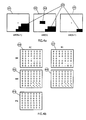
- Fig. 5a shows a diagram over time and the vertical field dimension, wherein crosses represent pixels of fields making up pictures in digital video signals. The pixel to be processed is marked in the diagram.
- Fig. 5b shows a diagram over vertical and horizontal field dimensions, wherein crosses represent pixels of one field. The pixel to be processed is marked in the diagram.
- the method is based on three-dimensional (including two spatial dimensions and one temporal dimension) processing of pixels associated with a current picture in a picture sequence in digital video signals.
- Every such pixel is processed by an error detector to determine whether the pixel is part of an error and, if so, to determine the error shape, i.e. a group of pixels, associated with the error. If the pixel is part of an error, the error shape is used by an adaptive filter for replacing the pixel with a mathematical median value of pixels associated with said current picture as well as pixels associated with at least one preceding picture and at least one following picture in the picture sequence.
- a picture sequence 102 is input to an error detector 107, an adaptive filter 103, a motion vector estimator 110, and a picture delay 101.
- the error detector 107 calculates inter-picture pixel contrasts and inter-picture activity. It may also make use of motion information 111 from the motion vector estimator 110.
- the error detector 107 detects an error if a pixel is found, which has at least a predetermined inter-picture contrast value and is not assumed to be part of a global or local movement in the picture sequence.
- the error detector 107 also determines a shape of a detected error, the shape being one single pixel or a group of immediately adjacent pixels which have at least a predetermined inter-picture contrast value and are not assumed to be part of a global or local movement in the picture sequence.
- An error shape signal 108 is output by the error detector 107 to the adaptive filter 103. If no error is detected, the output error shape signal 108 will indicate an error shape containing no pixels.
- the adaptive filter 103 replaces the intensity of a current pixel belonging to the error with an intensity being a mathematical function of pixel intensities of the current pixel and pixels surrounding the current pixel.
- the adaptive filter output is then fed to a mixing unit of 104.
- the motion information 111 may also be used in the adaptive filter 103 (no connection shown in Fig. 1) for compensating for inter-picture movement.
- the error detector 107 calculates a confidence value signal 109 corresponding to the likelihood that a current pixel has been correctly detected as an error pixel, the calculation of the likelihood being based on the difference matrices, including the inter-picture contrast matrices, the inter picture-activity measurement and, possibly, also the motion information 111.
- the confidence value is used for controlling a mixing of unfiltered pixels, delayed by a the picture delay 101 and pixels output by the adaptive filter 103. The mixing is carried out in the mixing unit 104, which outputs a filtered picture sequence in which high contrast errors have been removed.
- the inter-picture activity matrix and/or the motion information effect the confidence value, in such a way, that the influence of the adaptive filter output exerted on the filtered picture sequence 105 from the mixing unit 104, is inversely proportional to the inter-picture activity and/or motion contents of the matrices.
- a picture sequence origin signal 106 indicating the video fields corresponding to a picture in the picture sequence, e.g., film or video, 50 or 60Hz standard, is input to the error detector 107 and to the adaptive filter 103 for the purpose of adapting detection and filtering according to characteristics of errors and to the order of pixels, associated with a certain picture in the digital video signals.
- an analysing window 203 When processing a current pixel, an area in three consecutive pictures 201, 202, 204 in the picture sequence are compared. The three consecutive pictures 201, 202, 204 are separated in time as shown by a time axis 205. The area is referred to as the analysing window 203, which is centered around the position of the current pixel, the coordinate of which is marked with a cross in three consecutive pictures 201, 202, 204 in the picture sequence. The pixels, within the analysing window 203 in the three consecutive pictures 201, 202, 204, are used to calculate three difference matrices 206, 207, 210 (fig.
- the three difference matrices 206,207, 210 are calculated to contain pixel contrasts, i.e. differences in pixel intensity, associated with pixels within the analysing window of the three consecutive pictures.
- the two motion matrices 208, 209 are calculated to contain motion information, associated with pixels within the analysing window of the three consecutive pictures.
- the difference matrices 206,207 immediately adjacent pixels giving forward differences (FD11, ... , FDnn) and backward differences (BD11 ...
- the third difference matrix 210 the pixel contrasts between pictures P(N+1) and P(N-1) are calculated, which correspond to the the inter-picture activity represented by activity differences (AD11, ..., ADnn).
- the error detector may also use motion information, supplied by the motion vector estimator 110 (see, e.g, PCT/SE92/00219).
- the motion information is represented by forward motion vectors (FMV11, ... , FMVnn) and backward motion vectors (BMV11, ... , BMVnn) in the two motion matrices 208, 209.
- the motion vectors are used by the error detector in order to improve error detection accuracy, in such a way that pixels, which are part of true global or local movement in the picture sequence, are not detected as errors.
- an example of the use of an analysing window 301, 302, 305 in the error detector will be described. Shown within the analysing window 301, 302, 305, in three consecutive pictures, are a non-moving object 304 and an error 303.
- the error detector calculates the three difference matrices 306, 307, 310 and the two motion matrices 308, 309, in which the results are shown symbolically, with zeros for no intensity difference, zeros for no inter-picture activity, zeros for no motion, and minus signs for negative intensity differences.
- the error detector calculates the three difference matrices 406, 407, 410 and the two motion matrices 408, 409, in which the results are shown symbolically, with zeros for no intensity difference, zeros for no inter-picture activity, a numerical value indicating the inter-picture activity, zeros for no motion, arrows for motion vectors, plus signs for positive intensity differences, and minus signs for negative intensity differences.
- FIG. 5a shows pixels associated with the same field 503 as the pixel 506, which is currently being processed, as well as pixels associated with surrounding fields 501, 502, 504, 505, 508, 509, 510, 511.
- Fig. 5b shows pixels associated with the same field as a pixel 507, which is currently being processed.
- the origin of the picture sequence determines the particular field or fields, in the digital video signals, to which pixels associated with a certain picture belong.
- the adaptive filter uses a sub-set of the pixels, shown in figs. 5a and 5b, when filtering the current pixel 506, 507.
Landscapes
- Engineering & Computer Science (AREA)
- Multimedia (AREA)
- Signal Processing (AREA)
- Image Analysis (AREA)
- Compression Or Coding Systems Of Tv Signals (AREA)
- Television Signal Processing For Recording (AREA)
- Picture Signal Circuits (AREA)
- Facsimile Image Signal Circuits (AREA)
- Television Systems (AREA)
Claims (10)
- Verfahren zur Detektierung und Unterdrückung von Fehlern in Bildern, die zu einer Bildsequenz (102) in digitalen Videosignalen gehören, unter Verwendung eines Fehlerdetektors (107) und eines Filters (103) zur kontinuierlichen Verarbeitung von Pixeln, die zu den Bildern gehören,
dadurch gekennzeichnet, daß der Fehlerdetektor (107) einen Fehler detektiert, falls wenigstens ein Fehlerpixel, das ein Pixel mit einem Kontrast oberhalb eines spezifischen Kontrastes ist, d.h. ein Unterschied in Pixelintensitäten gefunden wird, wenn die Pixelintensitäten von Pixeln verglichen werden, die zu wenigstens zwei Bildern (201, 202, 204) in der Bildsequenz gehören, daß der Fehlerdetektor eine Fehlerform eines detektierten Fehlers bestimmt, wobei die Fehlerform eine Gruppe von Pixeln ist, die aus dem Fehlerpixel und, falls vorhanden, benachbarten Pixeln mit dem spezifischen Kontrast bestehen, und daß das Filter (103) ein adaptives Filter ist, das auf der Basis der Fehlerform und wenn ein aktuelles Pixel ein Fehlerpixel ist die Intensität des aktuellen Pixels durch eine Intensität ersetzt, die eine mathematische Funktion der Pixelintensitäten von Pixeln innerhalb und außerhalb der Fehlerform und außerdem von Pixeln ist, die zu wenigstens einem vorhergehenden Bild und wenigstens einem nachfolgenden Bild in der Bildsequenz gehören, während ein aktuelles Pixel, das kein Fehlerpixel ist, durch das adaptive Filter umgeleitet wird. - Verfahren nach Anspruch 1, wobei der Fehlerdetektor (107) ein Analysefenster (203) verwendet, das um die Position des aktuellen Pixels in drei aufeinanderfolgenden Bildern (201, 202, 204) in der Bildsequenz (102) herum zentriert ist.
- Verfahren nach Anspruch 2, wobei der Fehlerdetektor (107) für das Analysefenster (203) zwei Differenzmatrizen (207, 206) berechnet, die Unterschiede in Pixelintensitäten für ein aktuelles Bild (202) in bezug auf ein vorhergehendes Bild (204) und auf ein nachfolgendes Bild (201) der drei aufeinanderfolgenden Bilder beschreiben, wobei einander unmittelbar benachbarte Pixel, die Differenzen liefern, die einen vorbestimmten Pegel übersteigen und die in beiden Differenzmatrizen einander entsprechende Vorzeichen haben, der Fehlerform entsprechen.
- Verfahren nach Anspruch 2, wobei der Fehlerdetektor (107) für das Analysefenster (203) eine Differenzmatrix (210) berechnet, die eine Bild-zu-Bild-Aktivität beschreibt, die verwendet wird, um die Genauigkeit der Fehlerdetektierung zu verbessern.
- Verfahren nach Anspruch 1, wobei der Fehlerdetektor (107) außerdem Bewegungsinformationen (111) über die Bilder verwendet, um die Genauigkeit der Fehlerdetektierung zu verbessern, wobei die Informationen von einem Bewegungsvektor-Schätzer (110) geliefert werden.
- Verfahren nach Anspruch 2, wobei der Fehlerdetektor (107) außerdem Bewegungsinformationen (111) verwendet, die zu dem Analysefenster (203) in den Bildern gehören, um die Genauigkeit der Fehlerdetektierung zu verbessern, wobei die Informationen von einem Bewegungsvektor-Schätzer (110) geliefert werden.
- Verfahren nach Anspruch 1, wobei die Pixel in der Umgebung des aktuellen Pixels isotropisch, d.h. in allen drei Dimensionen, in bezug auf das aktuelle Pixel verteilt sind.
- Verfahren nach Anspruch 1, wobei die Herkunft der Bildsequenz erwartete Eigenschaften von Fehlern bestimmt und außerdem bestimmt, in welcher Reihenfolge Pixel, die zu den drei aufeinanderfolgenden Bildern gehören, in den digitalen Videosignalen liegen, und wobei die Herkunft zum Zwecke der Auswahl, welche Pixel in die Verarbeitung, Berechnung bzw. Filterung einzubeziehen sind, in den Fehlerdetektor und in das adaptive Filter eingegeben wird.
- Verfahren nach Anspruch 1, wobei die mathematische Funktion ein mathematischer Mittelwert der Pixelintensitäten der Pixel ist, von denen eine größere Zahl außerhalb der Fehlerform als innerhalb liegt.
- Verfahren nach einem der vorhergehenden Ansprüche, wobei der Fehlerdetektor (107) einen Konfidenzwert berechnet, der der Wahrscheinlichkeit entspricht, daß ein aktuelles Pixel korrekt als ein Fehlerpixel detektiert worden ist, wobei die Berechnung des Konfidenzwertes auf den Differenzmatrizen und, falls vorhanden, den Bewegungsinformationen basiert, worauf der Konfidenzwert verwendet wird, um eine Mischung von unverarbeiteten Pixeln und aus der kontinuierlichen Verarbeitung resultierenden Pixeln zu steuern.
Applications Claiming Priority (3)
| Application Number | Priority Date | Filing Date | Title |
|---|---|---|---|
| SE9201182 | 1992-04-13 | ||
| SE9201182A SE9201182L (sv) | 1992-04-13 | 1992-04-13 | Saett att detektera och avlaegsna fel oeverstigande en specifik kontrast i digitala videosignaler |
| PCT/SE1993/000314 WO1993021728A1 (en) | 1992-04-13 | 1993-04-08 | A method for detecting and removing errors exceeding a specific contrast in digital video signals |
Publications (2)
| Publication Number | Publication Date |
|---|---|
| EP0636299A1 EP0636299A1 (de) | 1995-02-01 |
| EP0636299B1 true EP0636299B1 (de) | 1997-11-19 |
Family
ID=20385955
Family Applications (1)
| Application Number | Title | Priority Date | Filing Date |
|---|---|---|---|
| EP93909121A Expired - Lifetime EP0636299B1 (de) | 1992-04-13 | 1993-04-08 | Verfahren zur detektierung und unterdrückung von fehlern in digitalen videosignalen, die einen spezifischen kontrast überschreiten |
Country Status (6)
| Country | Link |
|---|---|
| US (1) | US5606631A (de) |
| EP (1) | EP0636299B1 (de) |
| JP (1) | JP3283036B2 (de) |
| DE (1) | DE69315333T2 (de) |
| SE (1) | SE9201182L (de) |
| WO (1) | WO1993021728A1 (de) |
Families Citing this family (21)
| Publication number | Priority date | Publication date | Assignee | Title |
|---|---|---|---|---|
| DE69323855T2 (de) * | 1992-12-24 | 1999-09-16 | Canon K.K., Tokio/Tokyo | Vorrichtung für die Wiedergabe eines Bildsignals |
| EP0692120B1 (de) * | 1993-03-31 | 2002-10-09 | Luma Corporation | Informationsverwaltung in einem endoskopiesystem |
| JPH0951489A (ja) * | 1995-08-04 | 1997-02-18 | Sony Corp | データ符号化/復号化方法および装置 |
| US6052491A (en) | 1996-01-26 | 2000-04-18 | Texas Instruments Incorporated | Non-monotonic contour diffusion and algorithm |
| JPH09244609A (ja) * | 1996-03-06 | 1997-09-19 | Matsushita Electric Ind Co Ltd | 映像表示装置 |
| DE19636865C1 (de) * | 1996-09-11 | 1998-01-02 | Philips Patentverwaltung | Erkennung von schräglaufenden Kratzern in Videosignalen |
| DE19715983C1 (de) * | 1997-04-17 | 1998-09-24 | Aeg Infrarot Module Gmbh | Verfahren zum Korrigieren der Grauwerte von Bildern einer digitalen Infrarot-Kamera |
| US6201582B1 (en) * | 1997-09-19 | 2001-03-13 | Philips Electronics North America Corporation | Circuit for moiré suppression |
| US6535254B1 (en) * | 1997-10-31 | 2003-03-18 | Pinnacle Systems Inc. | Method and device for noise reduction |
| US6229578B1 (en) * | 1997-12-08 | 2001-05-08 | Intel Corporation | Edge-detection based noise removal algorithm |
| FR2777728B1 (fr) * | 1998-04-17 | 2000-06-23 | Inst Nat De L Audiovisuel | Procede de detection et de correction de defauts impulsifs apparaissant sur une image a traiter d'une sequence video numerique et un equipement pour la mise en oeuvre de ce procede |
| GB2361133B (en) | 2000-04-07 | 2004-04-14 | Snell & Wilcox Ltd | Video signal processing |
| GB2370932A (en) * | 2001-01-09 | 2002-07-10 | Sony Uk Ltd | Reduction in defect visibilty in image signals |
| US6987892B2 (en) * | 2001-04-19 | 2006-01-17 | Eastman Kodak Company | Method, system and software for correcting image defects |
| FR2830648B1 (fr) * | 2001-10-10 | 2004-01-16 | Eastman Kodak Co | Procede d'elimination de rayures dans des images numeriques |
| EP1545899A1 (de) * | 2002-09-10 | 2005-06-29 | Olof Karlsson | Verfahren und umschläge zum rationellen verschliessen von dokumenten und verschiedenen einlagen in umschlägen |
| JP2004193957A (ja) * | 2002-12-11 | 2004-07-08 | Konica Minolta Holdings Inc | 画像処理装置、画像処理方法、画像処理プログラムおよび画像記録装置 |
| US8289233B1 (en) | 2003-02-04 | 2012-10-16 | Imaging Systems Technology | Error diffusion |
| US8305301B1 (en) | 2003-02-04 | 2012-11-06 | Imaging Systems Technology | Gamma correction |
| US7596284B2 (en) * | 2003-07-16 | 2009-09-29 | Hewlett-Packard Development Company, L.P. | High resolution image reconstruction |
| US8248328B1 (en) | 2007-05-10 | 2012-08-21 | Imaging Systems Technology | Plasma-shell PDP with artifact reduction |
Family Cites Families (11)
| Publication number | Priority date | Publication date | Assignee | Title |
|---|---|---|---|---|
| US4573070A (en) * | 1977-01-31 | 1986-02-25 | Cooper J Carl | Noise reduction system for video signals |
| US4305091B2 (en) * | 1977-01-31 | 1998-02-10 | J Carl Cooper | Electronics noise reducing apparatus and method |
| DE3538735A1 (de) * | 1985-10-31 | 1987-05-07 | Bosch Gmbh Robert | Verfahren und schaltungsanordnung zum verdecken von fehlern in einem digitalen videosignal |
| DE3539415A1 (de) * | 1985-11-07 | 1987-05-14 | Bosch Gmbh Robert | Verfahren und schaltungsanordnung zum erkennen und verdecken von fehlern in einem digitalen videosignal |
| US4682230A (en) * | 1986-03-21 | 1987-07-21 | Rca Corporation | Adaptive median filter system |
| US4723166A (en) * | 1986-04-11 | 1988-02-02 | Harris Corporation | Noise adjusted recursive filter |
| US4838685A (en) * | 1987-04-03 | 1989-06-13 | Massachusetts Institute Of Technology | Methods and apparatus for motion estimation in motion picture processing |
| DE3719405C2 (de) * | 1987-06-11 | 1994-09-29 | Broadcast Television Syst | Schaltungsanordnung zur Verdeckung von Fehlern |
| EP0330269B1 (de) * | 1988-02-23 | 1993-09-22 | Koninklijke Philips Electronics N.V. | Verfahren und Anordnung zum Abschätzen des Bewegungsausmasses bei einem Bildelement eines Fernsehbildes |
| US5099329A (en) * | 1990-04-17 | 1992-03-24 | Graphic Communication Tech., Ltd. | Noise reduction method and device for image signal |
| JP2934036B2 (ja) * | 1991-03-07 | 1999-08-16 | 松下電器産業株式会社 | 動き検出方法およびノイズ低減装置 |
-
1992
- 1992-04-13 SE SE9201182A patent/SE9201182L/ not_active IP Right Cessation
-
1993
- 1993-04-08 EP EP93909121A patent/EP0636299B1/de not_active Expired - Lifetime
- 1993-04-08 DE DE69315333T patent/DE69315333T2/de not_active Expired - Fee Related
- 1993-04-08 WO PCT/SE1993/000314 patent/WO1993021728A1/en active IP Right Grant
- 1993-04-08 US US08/318,733 patent/US5606631A/en not_active Expired - Lifetime
- 1993-04-08 JP JP51823793A patent/JP3283036B2/ja not_active Expired - Fee Related
Also Published As
| Publication number | Publication date |
|---|---|
| DE69315333T2 (de) | 1998-04-09 |
| SE469411B (sv) | 1993-06-28 |
| DE69315333D1 (de) | 1998-01-02 |
| SE9201182D0 (sv) | 1992-04-13 |
| SE9201182L (sv) | 1993-06-28 |
| EP0636299A1 (de) | 1995-02-01 |
| JPH07505987A (ja) | 1995-06-29 |
| JP3283036B2 (ja) | 2002-05-20 |
| WO1993021728A1 (en) | 1993-10-28 |
| US5606631A (en) | 1997-02-25 |
Similar Documents
| Publication | Publication Date | Title |
|---|---|---|
| EP0636299B1 (de) | Verfahren zur detektierung und unterdrückung von fehlern in digitalen videosignalen, die einen spezifischen kontrast überschreiten | |
| US5387947A (en) | Motion vector detecting method of a video signal | |
| US4661853A (en) | Interfield image motion detector for video signals | |
| EP1570652B1 (de) | Verfahren und vorichtung zur bildstabilisierung | |
| US6081606A (en) | Apparatus and a method for detecting motion within an image sequence | |
| EP0636302B1 (de) | Verfahren zur adaptiven schätzung von unerwüschten bild-erschütterungen in bildsequenzen von digitalen fernsehsignalen | |
| CA2151079C (en) | Differential motion detection method using background image | |
| JP3164121B2 (ja) | 動きベクトル検出装置 | |
| EP0132832A2 (de) | Schaltung zur Feststellung einer Bildbewegung in einem Fernsehsignal mit Zeilensprung | |
| CA2134813A1 (en) | Film-to-video format detection for digital television | |
| EP0187641A1 (de) | Fernsehsystemumsetzer | |
| JPH0622298A (ja) | シーンチェンジ検出装置 | |
| GB2311436A (en) | Luminance/chrominance signal separating device with motion compensation | |
| JPH07203451A (ja) | テレビジョン信号における動きの階層的予測方法 | |
| US7218794B2 (en) | Method for detecting grid in block-based compressed video | |
| EP0403193A3 (de) | Verkehrsüberwachungsverfahren und -vorrichtung | |
| EP0333069B1 (de) | Vorrichtung und Verfahren zur Bewegungsdetektion in einem Videosignal | |
| CN1298172C (zh) | 检测静态区域 | |
| JP2792906B2 (ja) | パンニング検出回路 | |
| JPS6225587A (ja) | 動きベクトル検出回路 | |
| JPH0383474A (ja) | 車両検出装置 | |
| JPH02218284A (ja) | 自動車用追突防止警報装置 | |
| KR100213027B1 (ko) | 영상신호 잡음제거기 | |
| KR100249652B1 (ko) | 펄스성 노이즈 제거 장치 | |
| JPH10243340A (ja) | 動画像処理装置 |
Legal Events
| Date | Code | Title | Description |
|---|---|---|---|
| PUAI | Public reference made under article 153(3) epc to a published international application that has entered the european phase |
Free format text: ORIGINAL CODE: 0009012 |
|
| 17P | Request for examination filed |
Effective date: 19941024 |
|
| AK | Designated contracting states |
Kind code of ref document: A1 Designated state(s): DE FR GB |
|
| GRAG | Despatch of communication of intention to grant |
Free format text: ORIGINAL CODE: EPIDOS AGRA |
|
| 17Q | First examination report despatched |
Effective date: 19970307 |
|
| GRAH | Despatch of communication of intention to grant a patent |
Free format text: ORIGINAL CODE: EPIDOS IGRA |
|
| GRAH | Despatch of communication of intention to grant a patent |
Free format text: ORIGINAL CODE: EPIDOS IGRA |
|
| GRAA | (expected) grant |
Free format text: ORIGINAL CODE: 0009210 |
|
| AK | Designated contracting states |
Kind code of ref document: B1 Designated state(s): DE FR GB |
|
| ET | Fr: translation filed | ||
| REF | Corresponds to: |
Ref document number: 69315333 Country of ref document: DE Date of ref document: 19980102 |
|
| PLBE | No opposition filed within time limit |
Free format text: ORIGINAL CODE: 0009261 |
|
| STAA | Information on the status of an ep patent application or granted ep patent |
Free format text: STATUS: NO OPPOSITION FILED WITHIN TIME LIMIT |
|
| 26N | No opposition filed | ||
| REG | Reference to a national code |
Ref country code: GB Ref legal event code: IF02 |
|
| PGFP | Annual fee paid to national office [announced via postgrant information from national office to epo] |
Ref country code: FR Payment date: 20050330 Year of fee payment: 13 |
|
| PGFP | Annual fee paid to national office [announced via postgrant information from national office to epo] |
Ref country code: DE Payment date: 20050427 Year of fee payment: 13 |
|
| PG25 | Lapsed in a contracting state [announced via postgrant information from national office to epo] |
Ref country code: DE Free format text: LAPSE BECAUSE OF NON-PAYMENT OF DUE FEES Effective date: 20061101 |
|
| REG | Reference to a national code |
Ref country code: FR Ref legal event code: ST Effective date: 20061230 |
|
| PG25 | Lapsed in a contracting state [announced via postgrant information from national office to epo] |
Ref country code: FR Free format text: LAPSE BECAUSE OF NON-PAYMENT OF DUE FEES Effective date: 20060502 |
|
| PGFP | Annual fee paid to national office [announced via postgrant information from national office to epo] |
Ref country code: GB Payment date: 20110428 Year of fee payment: 19 |
|
| GBPC | Gb: european patent ceased through non-payment of renewal fee |
Effective date: 20120408 |
|
| PG25 | Lapsed in a contracting state [announced via postgrant information from national office to epo] |
Ref country code: GB Free format text: LAPSE BECAUSE OF NON-PAYMENT OF DUE FEES Effective date: 20120408 |