EP0635901B1 - Procédé de raccordement d'un câble électrique sur un élément d'extrémité et élément d'extrémité correspondant - Google Patents
Procédé de raccordement d'un câble électrique sur un élément d'extrémité et élément d'extrémité correspondant Download PDFInfo
- Publication number
- EP0635901B1 EP0635901B1 EP94401639A EP94401639A EP0635901B1 EP 0635901 B1 EP0635901 B1 EP 0635901B1 EP 94401639 A EP94401639 A EP 94401639A EP 94401639 A EP94401639 A EP 94401639A EP 0635901 B1 EP0635901 B1 EP 0635901B1
- Authority
- EP
- European Patent Office
- Prior art keywords
- cable
- section
- blind hole
- hole
- end member
- Prior art date
- Legal status (The legal status is an assumption and is not a legal conclusion. Google has not performed a legal analysis and makes no representation as to the accuracy of the status listed.)
- Expired - Lifetime
Links
Images


Classifications
-
- H—ELECTRICITY
- H01—ELECTRIC ELEMENTS
- H01R—ELECTRICALLY-CONDUCTIVE CONNECTIONS; STRUCTURAL ASSOCIATIONS OF A PLURALITY OF MUTUALLY-INSULATED ELECTRICAL CONNECTING ELEMENTS; COUPLING DEVICES; CURRENT COLLECTORS
- H01R4/00—Electrically-conductive connections between two or more conductive members in direct contact, i.e. touching one another; Means for effecting or maintaining such contact; Electrically-conductive connections having two or more spaced connecting locations for conductors and using contact members penetrating insulation
- H01R4/10—Electrically-conductive connections between two or more conductive members in direct contact, i.e. touching one another; Means for effecting or maintaining such contact; Electrically-conductive connections having two or more spaced connecting locations for conductors and using contact members penetrating insulation effected solely by twisting, wrapping, bending, crimping, or other permanent deformation
- H01R4/18—Electrically-conductive connections between two or more conductive members in direct contact, i.e. touching one another; Means for effecting or maintaining such contact; Electrically-conductive connections having two or more spaced connecting locations for conductors and using contact members penetrating insulation effected solely by twisting, wrapping, bending, crimping, or other permanent deformation by crimping
- H01R4/183—Electrically-conductive connections between two or more conductive members in direct contact, i.e. touching one another; Means for effecting or maintaining such contact; Electrically-conductive connections having two or more spaced connecting locations for conductors and using contact members penetrating insulation effected solely by twisting, wrapping, bending, crimping, or other permanent deformation by crimping for cylindrical elongated bodies, e.g. cables having circular cross-section
-
- Y—GENERAL TAGGING OF NEW TECHNOLOGICAL DEVELOPMENTS; GENERAL TAGGING OF CROSS-SECTIONAL TECHNOLOGIES SPANNING OVER SEVERAL SECTIONS OF THE IPC; TECHNICAL SUBJECTS COVERED BY FORMER USPC CROSS-REFERENCE ART COLLECTIONS [XRACs] AND DIGESTS
- Y10—TECHNICAL SUBJECTS COVERED BY FORMER USPC
- Y10T—TECHNICAL SUBJECTS COVERED BY FORMER US CLASSIFICATION
- Y10T29/00—Metal working
- Y10T29/49—Method of mechanical manufacture
- Y10T29/49002—Electrical device making
- Y10T29/49117—Conductor or circuit manufacturing
- Y10T29/49174—Assembling terminal to elongated conductor
- Y10T29/49181—Assembling terminal to elongated conductor by deforming
- Y10T29/49183—Assembling terminal to elongated conductor by deforming of ferrule about conductor and terminal
-
- Y—GENERAL TAGGING OF NEW TECHNOLOGICAL DEVELOPMENTS; GENERAL TAGGING OF CROSS-SECTIONAL TECHNOLOGIES SPANNING OVER SEVERAL SECTIONS OF THE IPC; TECHNICAL SUBJECTS COVERED BY FORMER USPC CROSS-REFERENCE ART COLLECTIONS [XRACs] AND DIGESTS
- Y10—TECHNICAL SUBJECTS COVERED BY FORMER USPC
- Y10T—TECHNICAL SUBJECTS COVERED BY FORMER US CLASSIFICATION
- Y10T29/00—Metal working
- Y10T29/49—Method of mechanical manufacture
- Y10T29/49002—Electrical device making
- Y10T29/49117—Conductor or circuit manufacturing
- Y10T29/49174—Assembling terminal to elongated conductor
- Y10T29/49181—Assembling terminal to elongated conductor by deforming
- Y10T29/49185—Assembling terminal to elongated conductor by deforming of terminal
-
- Y—GENERAL TAGGING OF NEW TECHNOLOGICAL DEVELOPMENTS; GENERAL TAGGING OF CROSS-SECTIONAL TECHNOLOGIES SPANNING OVER SEVERAL SECTIONS OF THE IPC; TECHNICAL SUBJECTS COVERED BY FORMER USPC CROSS-REFERENCE ART COLLECTIONS [XRACs] AND DIGESTS
- Y10—TECHNICAL SUBJECTS COVERED BY FORMER USPC
- Y10T—TECHNICAL SUBJECTS COVERED BY FORMER US CLASSIFICATION
- Y10T29/00—Metal working
- Y10T29/49—Method of mechanical manufacture
- Y10T29/49002—Electrical device making
- Y10T29/49117—Conductor or circuit manufacturing
- Y10T29/49194—Assembling elongated conductors, e.g., splicing, etc.
- Y10T29/49195—Assembling elongated conductors, e.g., splicing, etc. with end-to-end orienting
- Y10T29/49199—Assembling elongated conductors, e.g., splicing, etc. with end-to-end orienting including deforming of joining bridge
Definitions
- the invention relates to a method for connecting an electric cable to an end element such as a connector contact.
- the invention also relates to an end element which can be used for implementing this method.
- the invention applies mainly to the connection of electrical cables comprising a core of a light metal such as aluminum, coated with an insulating sheath.
- a light metal such as aluminum
- an insulating sheath it can also be used for the connection of cables whose core is made of any other material such as copper, in particular when a tightness of the connection is desired and / or when it is desired that the connection be made of non-aggressive for the cable.
- Another problem concerns the sensitivity of aluminum to chemical attack. This sensitivity means that the connection between the aluminum cable and the copper contact must be sealed, in order to isolate the aluminum from the ambient environment, which is not necessary when using a copper cable.
- the main object of the invention is a method for connecting an electric cable such as a cable with an aluminum core of small cross section on a end element such as an electrical contact ensuring a stable and reliable electrical connection, satisfactory mechanical strength as well as a seal against the external environment, without complicating the implementation, without rendering the standardized connectors currently used and preserving as much as possible the use of existing tools.
- the mechanical connection between the end element and the cable core is completed by a mechanical connection between the end element and the insulating sheath. Since the latter is generally made of plastic material with high mechanical and electrical performance, the mechanical strength is improved and makes it possible in particular to envisage the connection of a cable of small section with a light metal core. In addition, the connection thus produced is waterproof and is not aggressive for the cable.
- an end element which has at least one inspection hole which opens into a bottom section of the blind bore and a transparent sealing sleeve is placed in this section of bottom, before introducing the cable into the bore.
- the inspection hole makes it possible in particular to treat the interior of the blind bore, before placing the transparent sealing sleeve there. Thanks to the transparency of the sleeve, it also makes it possible to check the correct positioning of the cable core when the connection has been made. The transparent sleeve then preserves the tightness of the connection.
- an interface ring is also placed, made of an electrically conductive material such as silver, in an intermediate section of the bore, after having installed the transparent sealing sleeve in the bottom section and before introducing the cable into the bore.
- This interface ring is intended to improve the electrical contact between the cable core and the end element as well as to compensate for the difference in expansion between the materials constituting these two parts.
- the interface ring is chamfered inwards at its two ends.
- the invention also relates to an end element which can be used during the implementation of the connection method defined above.
- an end element mounted, by radial compaction, on the end of an electric cable, this element comprising a front part and a rear connection part, the latter comprising a blind bore, receiving one end. of the cable, and an outer surface having at least one frustoconical part whose diameter increases towards an open end of the bore, characterized in that, the end element being designed to be mounted on the end of a cable comprising a core coated with an insulating sheath, stripped over a length less than that of the blind bore, the latter is stepped and formed of at least two cylindrical sections each having a chamfered inlet end, a section of entry of the bore receiving a non-stripped part of the cable, the frustoconical part of the external surface being situated around the entry section and at least one at tre section of the bore, and the front part has a shoulder facing the rear connection part, capable of serving as an anchorage for a traction device, for the radial compaction of the rear connection part by drawing.
- the external surface of this bore comprises a cylindrical section which surrounds the bottom section of the bore and a frustoconical section which surrounds the intermediate section and the inlet section of the bore.
- an end element 10 such as an electrical contact
- an electrical cable 12 formed of a core 14 and an insulating sheath 16.
- the core 14 of cable 12 can be made of any metal, although the invention advantageously applies to the case where this core is made of a light metal such as aluminum.
- the insulating sheath 16 is made of a plastic material with high mechanical and electrical performance. It covers the core 14 of the cable 12, with the exception of its end which is stripped over a predetermined length L.
- the end element 10 is made of an electrically conductive material and having good cold deformation capabilities, such as a copper alloy.
- the end element 10 has a symmetry of revolution about a longitudinal axis and comprises a standardized front part 10a, strictly identical to the front part of the existing contacts, as well as a rear connection part 10b, the shape of which is modified in accordance with the invention.
- the front part 10a is identical to that of the standard male contacts.
- this front part 10a can take various shapes and dimensions depending on the application envisaged. These forms can in particular be those of a female contact or a tip.
- the front part 10a of the end element 10 has a flange 18 which defines a shoulder 20 facing the rear connection part 10b.
- the rear connection part 10b of the end element 10, which begins immediately behind the shoulder 20, has an external surface which successively defines, from this shoulder, a cylindrical part 22, of uniform diameter, and a tapered portion 24, the diameter of which increases from the cylindrical portion 22 to the rear end of the element 10. As illustrated in FIG. 1, the length of the tapered portion 24 is substantially double the length of the cylindrical part 22.
- a stepped blind bore 26 is formed coaxially in the rear connection part 10b of the end element 10 and extends to the inside of the flange 18.
- this bore 26 comprises a cylindrical bottom section 26a, of relatively small diameter, an intermediate cylindrical section 26b, the diameter of which is slightly greater than that of the bottom section 26a and a cylindrical inlet section 26c, the diameter of which is slightly greater than that of the section intermediate 26b.
- each of the cylindrical sections 26a, 26b and 26c has a chamfer 28a, 28b and 28c respectively.
- the bottom section 26a of the bore 26 is located entirely inside the cylindrical part 22 of the external surface of the rear connection part 10b.
- the intermediate section 26b of the bore 26 the length of which is slightly greater than that of the bottom section 26a, is mainly located inside the frustoconical part 24 of the outer surface of the rear connection part 10b and is extends slightly inside the cylindrical part 22.
- the inlet section 26c of the bore 26 is completely located inside the frustoconical part 24 and has a length less than that of the cylindrical sections 26a and 26b .
- the length L of the stripped part of the cable 12 is predetermined so as to be slightly greater than the abutment length of the sections 26a and 26b of the bore 26, but substantially less than the total length of this bore 26.
- the bottom section 26a of the bore 26 has a calibrated diameter equal to the diameter of the core 14 of the cable 12, increased by a slight clearance and by two thicknesses of a transparent sealing sleeve 30 intended to be mounted slightly by force in this bottom section 26a.
- the transparent sealing sleeve 30 can in particular be manufactured from a tubular sheath made of extruded plastic, sectioned at regular intervals. It has a completely symmetrical shape, so that it can be mounted in the bottom section 26a of the bore 26 without having to resort to a long and costly polarization.
- a manhole 32 is drilled radially in the rear connection part 10b of the end element 10, so as to lead to the cylindrical part 22 of the external surface of this rear part 10b and in the bottom section 26a of the bore 26.
- This inspection hole 32 facilitates the treatment of the surface of the blind bore 26, that is to say the possible deposit of protective coatings on this surface as well as its rinsing. It also makes it possible to visually check the presence of the core 14 of the cable 12 when the connection has been made.
- the intermediate cylindrical section 26b of the blind bore 26 has a calibrated diameter equal to the diameter of the core 14 of the cable 12, increased by a very slight clearance and by two thicknesses of an interface ring 34.
- the ring d interface 34 is designed to be mounted slightly by force in the intermediate section 26b of the bore 26. It is machined from a highly conductive material making it possible to improve the contact between the core 14 of the cable 12 (for example aluminum) and the end element 10 (for example made of copper alloy).
- the interface ring 34 also makes it possible to compensate for the difference in expansion between the materials constituting these two parts (coefficient of expansion of approximately 17 for a copper alloy and approximately 23 for an aluminum alloy).
- the interface ring 34 is advantageously made of silver. In fact, the conductivity of the silver is satisfactory and its coefficient of expansion is approximately 19. In addition, it is a metal which is easy to machine and relatively malleable.
- the presence of the interface ring 34 can sometimes be avoided. This is particularly the case when the core 14 of the cable 12 is also made of a copper alloy. This is also the case when this interface ring can be replaced by a metallic deposit fulfilling the same function inside the bore 26.
- the interface ring 34 has at each of its ends an internal chamfer 36. This symmetrical configuration of the interface ring 34 makes it possible to avoid having to resort to a long and costly polarization during assembly.
- a number of surface treatments are carried out on the end element 10, according to usual techniques. These surface treatments generally include copper plating of all the interior and exterior surfaces of the element 10, facilitating the adhesion of the other deposits. Nickel plating can also be carried out on the front part 10a of the element 10. It is also possible to carry out either a thin gilding on all the interior and exterior surfaces of the element 10, or a thick selective gilding on the front part 10a of this element. Finally, as already indicated, a deposit of money can be made inside the bore 26, in particular when it is desired to dispense with the interface ring 34.
- the inspection hole 32 makes it possible to escape the air contained in the bore 26 during the electrolytic deposition and facilitates the various rinses.
- the transparent sealing sleeve 30 is mounted slightly by force in the bottom section 26a of the bore 26. This operation is facilitated by the presence of the chamfer 28a at the entry of this section 26a. When it is finished, the transparent sealing sleeve 30 extends over the entire length of the bottom section 26a and thus seals the inspection hole 32 (FIG. 2B).
- the interface ring 34 is in turn mounted slightly by force in the intermediate section 26b of the bore 26. This operation is facilitated by the chamfer 28b which is located at the entrance to the section 26b. When it is finished, the interface ring 34 occupies the entire length of the intermediate section 26b.
- the introduction of the cable 10 is facilitated, for its core 14, by the chamfer 36 formed at the entrance to the interface ring 34 and, for its sheath 16, by the chamfer 28c formed at the entry of the entry section 26c of the bore 26.
- the penetration of the end of the core 14 into the transparent sealing sleeve 30 does not pose any particular problem, since the inside diameter of this sleeve is slightly greater than the inside diameter of the interface ring 34. It is visually checked, through the inspection hole 32, through the transparent sleeve 30.
- the introduction of the end of the cable 12 into the end element 10 is preceded or followed by the positioning of the end element 10 in a crimping tool illustrated very schematically.
- This crimping tool comprises a pliers 38 and a calibrated die 40.
- the clamp 38 is formed of at least two jaws which enclose the end element 10 around the cylindrical part 22 of its outer surface, so as to be able to bear on the shoulder 20, as illustrated in FIG. 2D .
- the die 40 is also formed of at least two half-shells which are closed on the cylindrical part 22 of the external surface of the end element 10, when the clamp 38 is closed as illustrated in FIG. 2D.
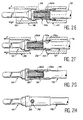
- the rear connection part 10b of the end element 10 is then radially compacted by wire drawing, as illustrated in FIGS. 2E and 2F.
- this drawing or crimping operation is carried out by exerting a tensile force on the end element 10, along its axis, by means of the clamp 38, so as to make pass over its entire length the rear connection part 10b through the calibrated die 40.
- This operation has the consequence of transforming the external surface of the rear connection part 10b into a cylindrical surface, the uniform diameter of which is substantially equal to the diameter initial of the cylindrical part 22.
- the intermediate section 26b and the inlet section 26c of the bore 26 are thus given shapes frustoconical whose diameter decreases towards the open end of the bore 26.
- the deformation of the intermediate section 26b of the bore results in a similar deformation of the interface ring 34.
- connection is thus made which is particularly suitable for the use of a cable with an aluminum core but whose tightness and non-aggressive nature make it possible to envisage its application in the case of a cable whose core is made in all other material including copper.
Landscapes
- Connections Effected By Soldering, Adhesion, Or Permanent Deformation (AREA)
- Mechanical Coupling Of Light Guides (AREA)
Applications Claiming Priority (2)
| Application Number | Priority Date | Filing Date | Title |
|---|---|---|---|
| FR9308818 | 1993-07-19 | ||
| FR9308818A FR2708150B1 (fr) | 1993-07-19 | 1993-07-19 | Procédé de raccordement d'un câble électrique sur un élément d'extrémité et élément d'extrémité correspondant. |
Publications (2)
| Publication Number | Publication Date |
|---|---|
| EP0635901A1 EP0635901A1 (fr) | 1995-01-25 |
| EP0635901B1 true EP0635901B1 (fr) | 1997-10-08 |
Family
ID=9449349
Family Applications (1)
| Application Number | Title | Priority Date | Filing Date |
|---|---|---|---|
| EP94401639A Expired - Lifetime EP0635901B1 (fr) | 1993-07-19 | 1994-07-18 | Procédé de raccordement d'un câble électrique sur un élément d'extrémité et élément d'extrémité correspondant |
Country Status (6)
| Country | Link |
|---|---|
| US (1) | US5499448A (es) |
| EP (1) | EP0635901B1 (es) |
| CA (1) | CA2127913C (es) |
| DE (1) | DE69406065T2 (es) |
| ES (1) | ES2110196T3 (es) |
| FR (1) | FR2708150B1 (es) |
Cited By (1)
| Publication number | Priority date | Publication date | Assignee | Title |
|---|---|---|---|---|
| EP2273618A1 (fr) * | 2009-07-08 | 2011-01-12 | Mecatraction | Dispositif de connexion à sertir pour câble électrique et procédé de fabrication d'un tel dispositif |
Families Citing this family (35)
| Publication number | Priority date | Publication date | Assignee | Title |
|---|---|---|---|---|
| ES2212514T3 (es) * | 1998-06-16 | 2004-07-16 | KABELKONFEKTION GEBAUER & GRILLER GMBH | Procedimiento para la conexion electrica y mecanica de componentes conductores de electricidad y dispositivo para la realizacion del procedimiento. |
| DE19843886A1 (de) * | 1998-09-24 | 2000-03-30 | Grote & Hartmann | Kabelschuh |
| US6453551B1 (en) * | 2000-06-02 | 2002-09-24 | Thaddeus E. Nordquist | Manufacture for feed-through devices |
| EP1617516A3 (en) * | 2000-09-21 | 2007-01-24 | Yazaki Corporation | Structure and method for connecting terminal and electric wire |
| JP2002124310A (ja) * | 2000-10-13 | 2002-04-26 | Yazaki Corp | 被覆電線の端子取付構造及び端子取付方法 |
| JP2002216862A (ja) * | 2001-01-19 | 2002-08-02 | Yazaki Corp | 端子と電線の接続部の防水構造及び防水方法 |
| US6739899B2 (en) * | 2001-07-25 | 2004-05-25 | Yazaki Corporation | Method and structure for connecting a terminal with a wire |
| US6805596B2 (en) * | 2002-04-16 | 2004-10-19 | Alcoa Fujikura Limited | Compression formed connector for a composite conductor assembly used in transmission line installations and method of constructing the same |
| JP4422391B2 (ja) * | 2002-08-07 | 2010-02-24 | 矢崎総業株式会社 | 電線と端子の接続方法 |
| EP2472675B1 (en) * | 2003-07-30 | 2020-09-30 | The Furukawa Electric Co., Ltd. | Terminal crimping structure and terminal crimping method onto aluminum electric-wire |
| JP2005050736A (ja) * | 2003-07-30 | 2005-02-24 | Furukawa Electric Co Ltd:The | アルミ電線への端子圧着構造及び端子付アルミ電線の製造方法 |
| US20070119562A1 (en) * | 2004-04-14 | 2007-05-31 | Gregory George R | System and method for termination of a wire rope |
| US7231957B2 (en) * | 2004-04-14 | 2007-06-19 | George Robert Gregory | System and method for termination of a wire rope |
| FR2873504B1 (fr) | 2004-07-26 | 2007-04-13 | Airbus France Sas | Outil et procede de sertissage d'un contact sur un cable |
| US7896712B2 (en) * | 2005-12-22 | 2011-03-01 | Tensolite, Llc | Integral bonding attachment |
| DE102007015696A1 (de) * | 2007-03-31 | 2008-10-02 | Gustav Klauke Gmbh | Kabelschuh |
| US7695331B2 (en) * | 2007-05-01 | 2010-04-13 | Tri-Star Technology | Electrical contact assembly including a sleeve member |
| US7611392B2 (en) * | 2007-09-17 | 2009-11-03 | Thomas & Betts International, Inc. | Terminal with integral strain relief |
| JP5079605B2 (ja) * | 2008-06-30 | 2012-11-21 | 株式会社オートネットワーク技術研究所 | 圧着端子及び端子付電線並びにこれらの製造方法 |
| FR2935202B1 (fr) * | 2008-08-21 | 2010-10-22 | Labinal | Dispositif de connexion entre un cable electrique et une structure conductrice, notamment pour circuit de retour de courant |
| US9385449B2 (en) * | 2009-02-16 | 2016-07-05 | Carlisle Interconnect Technologies, Inc. | Terminal/connector having integral oxide breaker element |
| JP5557377B2 (ja) * | 2010-03-23 | 2014-07-23 | 矢崎総業株式会社 | 端子の電線に対する接続構造 |
| EP2511983B1 (de) * | 2011-04-12 | 2016-03-23 | Nexans | Kabelschuh |
| CN102931499B (zh) * | 2011-08-11 | 2015-07-08 | 泰科电子(上海)有限公司 | 电连接组件 |
| US8845361B2 (en) * | 2011-11-08 | 2014-09-30 | Thomas & Betts International Llc | Explosion-proof electrical fitting |
| US10468785B1 (en) * | 2014-11-26 | 2019-11-05 | The National Telephone Supply Company | Crimp sleeve |
| US9985362B2 (en) | 2015-10-22 | 2018-05-29 | Carlisle Interconnect Technologies, Inc. | Arc resistant power terminal |
| JP6610392B2 (ja) * | 2016-04-07 | 2019-11-27 | 住友電装株式会社 | 導体の接続構造およびワイヤハーネス |
| DE102017105682A1 (de) * | 2017-03-16 | 2018-09-20 | Te Connectivity Germany Gmbh | Kontaktträger, elektrische Kontakteinrichtung sowie Verfahren zum Herstellen eines konfektionierten Kabels |
| DE102017114994B3 (de) * | 2017-07-05 | 2018-05-09 | Lisa Dräxlmaier GmbH | Verfahren zum herstellen einer elektrischen leitungsanordnung |
| GB201808026D0 (en) | 2018-05-17 | 2018-07-04 | Hubbell Ltd | Cable gland |
| WO2020096242A1 (ko) * | 2018-11-07 | 2020-05-14 | 엘에스전선 주식회사 | 전력케이블 중간접속구조 |
| US10923848B2 (en) * | 2018-12-14 | 2021-02-16 | Carlisle Interconnect Technologies, Inc. | Modular barrel contact system for electrical connectors |
| DE102020119423A1 (de) * | 2020-07-23 | 2022-01-27 | Md Elektronik Gmbh | Löthilfsteil sowie Verfahren zur Befestigung eines Kabels an einer Leiterfläche |
| DE102022100191A1 (de) * | 2022-01-05 | 2023-07-06 | EngstKabel GmbH & Co. KG | Verbesserte leitfähige Hülse und Verfahren zum Verbinden eines Leiterabschnitts mit der leitfähigen Hülse |
Family Cites Families (7)
| Publication number | Priority date | Publication date | Assignee | Title |
|---|---|---|---|---|
| US2297785A (en) * | 1941-09-13 | 1942-10-06 | Ibm | Terminal for electrical conductors |
| US2803695A (en) * | 1951-05-03 | 1957-08-20 | Amp Inc | Closed end connector |
| US3010184A (en) * | 1958-11-13 | 1961-11-28 | Amp Inc | Method of making an electrical connection |
| FR1260806A (fr) * | 1960-03-31 | 1961-05-12 | Materiel Electr Soc Ind De | Perfectionnement aux procédés de sertissage de manchons sur câbles métalliques |
| GB954409A (en) * | 1962-01-09 | 1964-04-08 | Cable Covers Ltd | Compression connectors for joining or terminating wires, rods and other suitable members |
| DE2544927A1 (de) * | 1975-10-07 | 1977-04-21 | Roesler Karl Heinz | Kabelbefestigungselement, insbesondere kabelschuh fuer batterieladekabel o.dgl. |
| FR2613541B1 (fr) * | 1987-04-06 | 1990-04-06 | Labinal | Procede de realisation de cosses en plomb ou objets analogues sur des cables en aluminium |
-
1993
- 1993-07-19 FR FR9308818A patent/FR2708150B1/fr not_active Expired - Fee Related
-
1994
- 1994-07-13 CA CA002127913A patent/CA2127913C/en not_active Expired - Fee Related
- 1994-07-15 US US08/275,953 patent/US5499448A/en not_active Expired - Lifetime
- 1994-07-18 ES ES94401639T patent/ES2110196T3/es not_active Expired - Lifetime
- 1994-07-18 DE DE69406065T patent/DE69406065T2/de not_active Expired - Lifetime
- 1994-07-18 EP EP94401639A patent/EP0635901B1/fr not_active Expired - Lifetime
Cited By (2)
| Publication number | Priority date | Publication date | Assignee | Title |
|---|---|---|---|---|
| EP2273618A1 (fr) * | 2009-07-08 | 2011-01-12 | Mecatraction | Dispositif de connexion à sertir pour câble électrique et procédé de fabrication d'un tel dispositif |
| FR2947960A1 (fr) * | 2009-07-08 | 2011-01-14 | Mecatraction | Dispositif de connexion a sertir pour cable electrique et procede de fabrication d'un tel dispositif |
Also Published As
| Publication number | Publication date |
|---|---|
| DE69406065D1 (de) | 1997-11-13 |
| FR2708150B1 (fr) | 1995-10-13 |
| DE69406065T2 (de) | 1998-04-09 |
| ES2110196T3 (es) | 1998-02-01 |
| FR2708150A1 (fr) | 1995-01-27 |
| EP0635901A1 (fr) | 1995-01-25 |
| CA2127913A1 (en) | 1995-01-20 |
| US5499448A (en) | 1996-03-19 |
| CA2127913C (en) | 2005-10-25 |
Similar Documents
| Publication | Publication Date | Title |
|---|---|---|
| EP0635901B1 (fr) | Procédé de raccordement d'un câble électrique sur un élément d'extrémité et élément d'extrémité correspondant | |
| EP0576666B1 (fr) | Procede de raccordement d'un cable electrique comportant une ame en metal leger sur un element d'extremite normalise, et piece de raccordement pour la mise en oeuvre de ce procede | |
| EP0439411B1 (fr) | Isolateur composite et son procédé de fabrication | |
| FR2500638A1 (fr) | Cable a fibres optiques | |
| EP2273618A1 (fr) | Dispositif de connexion à sertir pour câble électrique et procédé de fabrication d'un tel dispositif | |
| FR3057717A1 (fr) | Systeme sous-marin de raccordement electrique | |
| FR3070798A1 (fr) | Connexion de cable et procede de connexion de cable | |
| EP0154588B1 (fr) | Procédé de réalisation de raccords démontables et assurant l'étanchéité de conduites haute pression, et raccords ainsi constitués | |
| EP1469560A1 (fr) | Pièce de contact pour connecteur électrique | |
| EP1383211B1 (fr) | Procédé de sertissage d'un contact sur des brins d'un câble | |
| FR2667449A1 (fr) | Connecteur pour un cable coaxial blinde. | |
| FR2475306A1 (fr) | Boite de jonction universelle pour cables de telecommunications ou de puissance | |
| CA2434592A1 (fr) | Dispositif de liaison entre un cable et un element de contact | |
| FR2633103A1 (fr) | Embout de cablage | |
| FR2853151A1 (fr) | Procede pour rendre etanche un cable de liaison multibrins de mise a la masse | |
| CA1248192A (fr) | Element de raccordement entre un conducteur electrique et un contact de connecteur | |
| EP0016715B1 (fr) | Dispositif d'étanchéité et procédé d'assemblage étanche d'un manchon à un conducteur électrique isolé ou à un tuyau et son mode de fabrication | |
| FR2884974A1 (fr) | Raccord de cables a ame conductrice sur cosses electriques | |
| EP0864798B2 (fr) | Procédé pour raccorder une canalisation souple à un tube rigide, frette pour la mise en oeuvre du procédé et raccord obtenu | |
| FR2497392A1 (fr) | Cable electro-tracteur | |
| FR3061810A1 (fr) | Dispositif de connexion entre les ecrans de deux elements de cable electrique | |
| EP3062407B1 (fr) | Manchon de raccord entre câbles conducteurs, procédé de fabrication et procédé de mise en oeuvre d'un tel manchon. | |
| FR2683396A1 (fr) | Contact electrique pour cable electrique a ame en aluminium et connecteur electrique equipe d'au moins un tel contact. | |
| FR2475304A1 (fr) | Cosse de raccordement entre un cable et une borne de jonction et procede pour realiser la cosse | |
| FR2546680A1 (fr) | Procede de fabrication d'un manchon d'ancrage a cable passant pour conducteur electrique nu, et manchon ainsi obtenu |
Legal Events
| Date | Code | Title | Description |
|---|---|---|---|
| PUAI | Public reference made under article 153(3) epc to a published international application that has entered the european phase |
Free format text: ORIGINAL CODE: 0009012 |
|
| AK | Designated contracting states |
Kind code of ref document: A1 Designated state(s): DE ES GB IT NL |
|
| 17P | Request for examination filed |
Effective date: 19950629 |
|
| 17Q | First examination report despatched |
Effective date: 19960502 |
|
| GRAG | Despatch of communication of intention to grant |
Free format text: ORIGINAL CODE: EPIDOS AGRA |
|
| GRAH | Despatch of communication of intention to grant a patent |
Free format text: ORIGINAL CODE: EPIDOS IGRA |
|
| GRAH | Despatch of communication of intention to grant a patent |
Free format text: ORIGINAL CODE: EPIDOS IGRA |
|
| GRAA | (expected) grant |
Free format text: ORIGINAL CODE: 0009210 |
|
| AK | Designated contracting states |
Kind code of ref document: B1 Designated state(s): DE ES GB IT NL |
|
| REF | Corresponds to: |
Ref document number: 69406065 Country of ref document: DE Date of ref document: 19971113 |
|
| ITF | It: translation for a ep patent filed |
Owner name: PROPRIA PROTEZIONE PROPR. IND. |
|
| GBT | Gb: translation of ep patent filed (gb section 77(6)(a)/1977) |
Effective date: 19971212 |
|
| REG | Reference to a national code |
Ref country code: ES Ref legal event code: FG2A Ref document number: 2110196 Country of ref document: ES Kind code of ref document: T3 |
|
| PLBE | No opposition filed within time limit |
Free format text: ORIGINAL CODE: 0009261 |
|
| STAA | Information on the status of an ep patent application or granted ep patent |
Free format text: STATUS: NO OPPOSITION FILED WITHIN TIME LIMIT |
|
| 26N | No opposition filed | ||
| REG | Reference to a national code |
Ref country code: GB Ref legal event code: IF02 |
|
| PGFP | Annual fee paid to national office [announced via postgrant information from national office to epo] |
Ref country code: ES Payment date: 20090724 Year of fee payment: 16 |
|
| PGFP | Annual fee paid to national office [announced via postgrant information from national office to epo] |
Ref country code: NL Payment date: 20090730 Year of fee payment: 16 |
|
| PGFP | Annual fee paid to national office [announced via postgrant information from national office to epo] |
Ref country code: IT Payment date: 20100726 Year of fee payment: 17 Ref country code: DE Payment date: 20100723 Year of fee payment: 17 |
|
| PGFP | Annual fee paid to national office [announced via postgrant information from national office to epo] |
Ref country code: GB Payment date: 20100722 Year of fee payment: 17 |
|
| REG | Reference to a national code |
Ref country code: NL Ref legal event code: V1 Effective date: 20110201 |
|
| PG25 | Lapsed in a contracting state [announced via postgrant information from national office to epo] |
Ref country code: NL Free format text: LAPSE BECAUSE OF NON-PAYMENT OF DUE FEES Effective date: 20110201 |
|
| REG | Reference to a national code |
Ref country code: ES Ref legal event code: FD2A Effective date: 20110818 |
|
| PG25 | Lapsed in a contracting state [announced via postgrant information from national office to epo] |
Ref country code: ES Free format text: LAPSE BECAUSE OF NON-PAYMENT OF DUE FEES Effective date: 20100719 |
|
| GBPC | Gb: european patent ceased through non-payment of renewal fee |
Effective date: 20110718 |
|
| PG25 | Lapsed in a contracting state [announced via postgrant information from national office to epo] |
Ref country code: DE Free format text: LAPSE BECAUSE OF NON-PAYMENT OF DUE FEES Effective date: 20120201 |
|
| REG | Reference to a national code |
Ref country code: DE Ref legal event code: R119 Ref document number: 69406065 Country of ref document: DE Effective date: 20120201 |
|
| PG25 | Lapsed in a contracting state [announced via postgrant information from national office to epo] |
Ref country code: IT Free format text: LAPSE BECAUSE OF NON-PAYMENT OF DUE FEES Effective date: 20110718 |
|
| PG25 | Lapsed in a contracting state [announced via postgrant information from national office to epo] |
Ref country code: GB Free format text: LAPSE BECAUSE OF NON-PAYMENT OF DUE FEES Effective date: 20110718 |