EP0635901B1 - Process for connecting an electric cable to a terminal element and correspondant terminal element - Google Patents
Process for connecting an electric cable to a terminal element and correspondant terminal element Download PDFInfo
- Publication number
- EP0635901B1 EP0635901B1 EP94401639A EP94401639A EP0635901B1 EP 0635901 B1 EP0635901 B1 EP 0635901B1 EP 94401639 A EP94401639 A EP 94401639A EP 94401639 A EP94401639 A EP 94401639A EP 0635901 B1 EP0635901 B1 EP 0635901B1
- Authority
- EP
- European Patent Office
- Prior art keywords
- cable
- section
- blind hole
- hole
- end member
- Prior art date
- Legal status (The legal status is an assumption and is not a legal conclusion. Google has not performed a legal analysis and makes no representation as to the accuracy of the status listed.)
- Expired - Lifetime
Links
Images


Classifications
-
- H—ELECTRICITY
- H01—ELECTRIC ELEMENTS
- H01R—ELECTRICALLY-CONDUCTIVE CONNECTIONS; STRUCTURAL ASSOCIATIONS OF A PLURALITY OF MUTUALLY-INSULATED ELECTRICAL CONNECTING ELEMENTS; COUPLING DEVICES; CURRENT COLLECTORS
- H01R4/00—Electrically-conductive connections between two or more conductive members in direct contact, i.e. touching one another; Means for effecting or maintaining such contact; Electrically-conductive connections having two or more spaced connecting locations for conductors and using contact members penetrating insulation
- H01R4/10—Electrically-conductive connections between two or more conductive members in direct contact, i.e. touching one another; Means for effecting or maintaining such contact; Electrically-conductive connections having two or more spaced connecting locations for conductors and using contact members penetrating insulation effected solely by twisting, wrapping, bending, crimping, or other permanent deformation
- H01R4/18—Electrically-conductive connections between two or more conductive members in direct contact, i.e. touching one another; Means for effecting or maintaining such contact; Electrically-conductive connections having two or more spaced connecting locations for conductors and using contact members penetrating insulation effected solely by twisting, wrapping, bending, crimping, or other permanent deformation by crimping
- H01R4/183—Electrically-conductive connections between two or more conductive members in direct contact, i.e. touching one another; Means for effecting or maintaining such contact; Electrically-conductive connections having two or more spaced connecting locations for conductors and using contact members penetrating insulation effected solely by twisting, wrapping, bending, crimping, or other permanent deformation by crimping for cylindrical elongated bodies, e.g. cables having circular cross-section
-
- Y—GENERAL TAGGING OF NEW TECHNOLOGICAL DEVELOPMENTS; GENERAL TAGGING OF CROSS-SECTIONAL TECHNOLOGIES SPANNING OVER SEVERAL SECTIONS OF THE IPC; TECHNICAL SUBJECTS COVERED BY FORMER USPC CROSS-REFERENCE ART COLLECTIONS [XRACs] AND DIGESTS
- Y10—TECHNICAL SUBJECTS COVERED BY FORMER USPC
- Y10T—TECHNICAL SUBJECTS COVERED BY FORMER US CLASSIFICATION
- Y10T29/00—Metal working
- Y10T29/49—Method of mechanical manufacture
- Y10T29/49002—Electrical device making
- Y10T29/49117—Conductor or circuit manufacturing
- Y10T29/49174—Assembling terminal to elongated conductor
- Y10T29/49181—Assembling terminal to elongated conductor by deforming
- Y10T29/49183—Assembling terminal to elongated conductor by deforming of ferrule about conductor and terminal
-
- Y—GENERAL TAGGING OF NEW TECHNOLOGICAL DEVELOPMENTS; GENERAL TAGGING OF CROSS-SECTIONAL TECHNOLOGIES SPANNING OVER SEVERAL SECTIONS OF THE IPC; TECHNICAL SUBJECTS COVERED BY FORMER USPC CROSS-REFERENCE ART COLLECTIONS [XRACs] AND DIGESTS
- Y10—TECHNICAL SUBJECTS COVERED BY FORMER USPC
- Y10T—TECHNICAL SUBJECTS COVERED BY FORMER US CLASSIFICATION
- Y10T29/00—Metal working
- Y10T29/49—Method of mechanical manufacture
- Y10T29/49002—Electrical device making
- Y10T29/49117—Conductor or circuit manufacturing
- Y10T29/49174—Assembling terminal to elongated conductor
- Y10T29/49181—Assembling terminal to elongated conductor by deforming
- Y10T29/49185—Assembling terminal to elongated conductor by deforming of terminal
-
- Y—GENERAL TAGGING OF NEW TECHNOLOGICAL DEVELOPMENTS; GENERAL TAGGING OF CROSS-SECTIONAL TECHNOLOGIES SPANNING OVER SEVERAL SECTIONS OF THE IPC; TECHNICAL SUBJECTS COVERED BY FORMER USPC CROSS-REFERENCE ART COLLECTIONS [XRACs] AND DIGESTS
- Y10—TECHNICAL SUBJECTS COVERED BY FORMER USPC
- Y10T—TECHNICAL SUBJECTS COVERED BY FORMER US CLASSIFICATION
- Y10T29/00—Metal working
- Y10T29/49—Method of mechanical manufacture
- Y10T29/49002—Electrical device making
- Y10T29/49117—Conductor or circuit manufacturing
- Y10T29/49194—Assembling elongated conductors, e.g., splicing, etc.
- Y10T29/49195—Assembling elongated conductors, e.g., splicing, etc. with end-to-end orienting
- Y10T29/49199—Assembling elongated conductors, e.g., splicing, etc. with end-to-end orienting including deforming of joining bridge
Definitions
- the invention relates to a method for connecting an electric cable to an end element such as a connector contact.
- the invention also relates to an end element which can be used for implementing this method.
- the invention applies mainly to the connection of electrical cables comprising a core of a light metal such as aluminum, coated with an insulating sheath.
- a light metal such as aluminum
- an insulating sheath it can also be used for the connection of cables whose core is made of any other material such as copper, in particular when a tightness of the connection is desired and / or when it is desired that the connection be made of non-aggressive for the cable.
- Another problem concerns the sensitivity of aluminum to chemical attack. This sensitivity means that the connection between the aluminum cable and the copper contact must be sealed, in order to isolate the aluminum from the ambient environment, which is not necessary when using a copper cable.
- the main object of the invention is a method for connecting an electric cable such as a cable with an aluminum core of small cross section on a end element such as an electrical contact ensuring a stable and reliable electrical connection, satisfactory mechanical strength as well as a seal against the external environment, without complicating the implementation, without rendering the standardized connectors currently used and preserving as much as possible the use of existing tools.
- the mechanical connection between the end element and the cable core is completed by a mechanical connection between the end element and the insulating sheath. Since the latter is generally made of plastic material with high mechanical and electrical performance, the mechanical strength is improved and makes it possible in particular to envisage the connection of a cable of small section with a light metal core. In addition, the connection thus produced is waterproof and is not aggressive for the cable.
- an end element which has at least one inspection hole which opens into a bottom section of the blind bore and a transparent sealing sleeve is placed in this section of bottom, before introducing the cable into the bore.
- the inspection hole makes it possible in particular to treat the interior of the blind bore, before placing the transparent sealing sleeve there. Thanks to the transparency of the sleeve, it also makes it possible to check the correct positioning of the cable core when the connection has been made. The transparent sleeve then preserves the tightness of the connection.
- an interface ring is also placed, made of an electrically conductive material such as silver, in an intermediate section of the bore, after having installed the transparent sealing sleeve in the bottom section and before introducing the cable into the bore.
- This interface ring is intended to improve the electrical contact between the cable core and the end element as well as to compensate for the difference in expansion between the materials constituting these two parts.
- the interface ring is chamfered inwards at its two ends.
- the invention also relates to an end element which can be used during the implementation of the connection method defined above.
- an end element mounted, by radial compaction, on the end of an electric cable, this element comprising a front part and a rear connection part, the latter comprising a blind bore, receiving one end. of the cable, and an outer surface having at least one frustoconical part whose diameter increases towards an open end of the bore, characterized in that, the end element being designed to be mounted on the end of a cable comprising a core coated with an insulating sheath, stripped over a length less than that of the blind bore, the latter is stepped and formed of at least two cylindrical sections each having a chamfered inlet end, a section of entry of the bore receiving a non-stripped part of the cable, the frustoconical part of the external surface being situated around the entry section and at least one at tre section of the bore, and the front part has a shoulder facing the rear connection part, capable of serving as an anchorage for a traction device, for the radial compaction of the rear connection part by drawing.
- the external surface of this bore comprises a cylindrical section which surrounds the bottom section of the bore and a frustoconical section which surrounds the intermediate section and the inlet section of the bore.
- an end element 10 such as an electrical contact
- an electrical cable 12 formed of a core 14 and an insulating sheath 16.
- the core 14 of cable 12 can be made of any metal, although the invention advantageously applies to the case where this core is made of a light metal such as aluminum.
- the insulating sheath 16 is made of a plastic material with high mechanical and electrical performance. It covers the core 14 of the cable 12, with the exception of its end which is stripped over a predetermined length L.
- the end element 10 is made of an electrically conductive material and having good cold deformation capabilities, such as a copper alloy.
- the end element 10 has a symmetry of revolution about a longitudinal axis and comprises a standardized front part 10a, strictly identical to the front part of the existing contacts, as well as a rear connection part 10b, the shape of which is modified in accordance with the invention.
- the front part 10a is identical to that of the standard male contacts.
- this front part 10a can take various shapes and dimensions depending on the application envisaged. These forms can in particular be those of a female contact or a tip.
- the front part 10a of the end element 10 has a flange 18 which defines a shoulder 20 facing the rear connection part 10b.
- the rear connection part 10b of the end element 10, which begins immediately behind the shoulder 20, has an external surface which successively defines, from this shoulder, a cylindrical part 22, of uniform diameter, and a tapered portion 24, the diameter of which increases from the cylindrical portion 22 to the rear end of the element 10. As illustrated in FIG. 1, the length of the tapered portion 24 is substantially double the length of the cylindrical part 22.
- a stepped blind bore 26 is formed coaxially in the rear connection part 10b of the end element 10 and extends to the inside of the flange 18.
- this bore 26 comprises a cylindrical bottom section 26a, of relatively small diameter, an intermediate cylindrical section 26b, the diameter of which is slightly greater than that of the bottom section 26a and a cylindrical inlet section 26c, the diameter of which is slightly greater than that of the section intermediate 26b.
- each of the cylindrical sections 26a, 26b and 26c has a chamfer 28a, 28b and 28c respectively.
- the bottom section 26a of the bore 26 is located entirely inside the cylindrical part 22 of the external surface of the rear connection part 10b.
- the intermediate section 26b of the bore 26 the length of which is slightly greater than that of the bottom section 26a, is mainly located inside the frustoconical part 24 of the outer surface of the rear connection part 10b and is extends slightly inside the cylindrical part 22.
- the inlet section 26c of the bore 26 is completely located inside the frustoconical part 24 and has a length less than that of the cylindrical sections 26a and 26b .
- the length L of the stripped part of the cable 12 is predetermined so as to be slightly greater than the abutment length of the sections 26a and 26b of the bore 26, but substantially less than the total length of this bore 26.
- the bottom section 26a of the bore 26 has a calibrated diameter equal to the diameter of the core 14 of the cable 12, increased by a slight clearance and by two thicknesses of a transparent sealing sleeve 30 intended to be mounted slightly by force in this bottom section 26a.
- the transparent sealing sleeve 30 can in particular be manufactured from a tubular sheath made of extruded plastic, sectioned at regular intervals. It has a completely symmetrical shape, so that it can be mounted in the bottom section 26a of the bore 26 without having to resort to a long and costly polarization.
- a manhole 32 is drilled radially in the rear connection part 10b of the end element 10, so as to lead to the cylindrical part 22 of the external surface of this rear part 10b and in the bottom section 26a of the bore 26.
- This inspection hole 32 facilitates the treatment of the surface of the blind bore 26, that is to say the possible deposit of protective coatings on this surface as well as its rinsing. It also makes it possible to visually check the presence of the core 14 of the cable 12 when the connection has been made.
- the intermediate cylindrical section 26b of the blind bore 26 has a calibrated diameter equal to the diameter of the core 14 of the cable 12, increased by a very slight clearance and by two thicknesses of an interface ring 34.
- the ring d interface 34 is designed to be mounted slightly by force in the intermediate section 26b of the bore 26. It is machined from a highly conductive material making it possible to improve the contact between the core 14 of the cable 12 (for example aluminum) and the end element 10 (for example made of copper alloy).
- the interface ring 34 also makes it possible to compensate for the difference in expansion between the materials constituting these two parts (coefficient of expansion of approximately 17 for a copper alloy and approximately 23 for an aluminum alloy).
- the interface ring 34 is advantageously made of silver. In fact, the conductivity of the silver is satisfactory and its coefficient of expansion is approximately 19. In addition, it is a metal which is easy to machine and relatively malleable.
- the presence of the interface ring 34 can sometimes be avoided. This is particularly the case when the core 14 of the cable 12 is also made of a copper alloy. This is also the case when this interface ring can be replaced by a metallic deposit fulfilling the same function inside the bore 26.
- the interface ring 34 has at each of its ends an internal chamfer 36. This symmetrical configuration of the interface ring 34 makes it possible to avoid having to resort to a long and costly polarization during assembly.
- a number of surface treatments are carried out on the end element 10, according to usual techniques. These surface treatments generally include copper plating of all the interior and exterior surfaces of the element 10, facilitating the adhesion of the other deposits. Nickel plating can also be carried out on the front part 10a of the element 10. It is also possible to carry out either a thin gilding on all the interior and exterior surfaces of the element 10, or a thick selective gilding on the front part 10a of this element. Finally, as already indicated, a deposit of money can be made inside the bore 26, in particular when it is desired to dispense with the interface ring 34.
- the inspection hole 32 makes it possible to escape the air contained in the bore 26 during the electrolytic deposition and facilitates the various rinses.
- the transparent sealing sleeve 30 is mounted slightly by force in the bottom section 26a of the bore 26. This operation is facilitated by the presence of the chamfer 28a at the entry of this section 26a. When it is finished, the transparent sealing sleeve 30 extends over the entire length of the bottom section 26a and thus seals the inspection hole 32 (FIG. 2B).
- the interface ring 34 is in turn mounted slightly by force in the intermediate section 26b of the bore 26. This operation is facilitated by the chamfer 28b which is located at the entrance to the section 26b. When it is finished, the interface ring 34 occupies the entire length of the intermediate section 26b.
- the introduction of the cable 10 is facilitated, for its core 14, by the chamfer 36 formed at the entrance to the interface ring 34 and, for its sheath 16, by the chamfer 28c formed at the entry of the entry section 26c of the bore 26.
- the penetration of the end of the core 14 into the transparent sealing sleeve 30 does not pose any particular problem, since the inside diameter of this sleeve is slightly greater than the inside diameter of the interface ring 34. It is visually checked, through the inspection hole 32, through the transparent sleeve 30.
- the introduction of the end of the cable 12 into the end element 10 is preceded or followed by the positioning of the end element 10 in a crimping tool illustrated very schematically.
- This crimping tool comprises a pliers 38 and a calibrated die 40.
- the clamp 38 is formed of at least two jaws which enclose the end element 10 around the cylindrical part 22 of its outer surface, so as to be able to bear on the shoulder 20, as illustrated in FIG. 2D .
- the die 40 is also formed of at least two half-shells which are closed on the cylindrical part 22 of the external surface of the end element 10, when the clamp 38 is closed as illustrated in FIG. 2D.
- the rear connection part 10b of the end element 10 is then radially compacted by wire drawing, as illustrated in FIGS. 2E and 2F.
- this drawing or crimping operation is carried out by exerting a tensile force on the end element 10, along its axis, by means of the clamp 38, so as to make pass over its entire length the rear connection part 10b through the calibrated die 40.
- This operation has the consequence of transforming the external surface of the rear connection part 10b into a cylindrical surface, the uniform diameter of which is substantially equal to the diameter initial of the cylindrical part 22.
- the intermediate section 26b and the inlet section 26c of the bore 26 are thus given shapes frustoconical whose diameter decreases towards the open end of the bore 26.
- the deformation of the intermediate section 26b of the bore results in a similar deformation of the interface ring 34.
- connection is thus made which is particularly suitable for the use of a cable with an aluminum core but whose tightness and non-aggressive nature make it possible to envisage its application in the case of a cable whose core is made in all other material including copper.
Description
L'invention concerne un procédé permettant de raccorder un câble électrique sur un élément d'extrémité tel qu'un contact de connecteur. L'invention concerne également un élément d'extrémité utilisable pour la mise en oeuvre de ce procédé.The invention relates to a method for connecting an electric cable to an end element such as a connector contact. The invention also relates to an end element which can be used for implementing this method.
L'invention s'applique principalement au raccordement de câbles électriques comportant une âme en un métal léger tel que de l'aluminium, revêtu d'une gaine isolante. Toutefois, elle peut aussi être utilisée pour le raccordement de câbles dont l'âme est réalisée en tout autre matériau tel que du cuivre, notamment lorsqu'une étanchéité de la connexion est souhaitée et/ou lorsqu'on désire que le raccordement soit réalisé de manière non agressive pour le câble.The invention applies mainly to the connection of electrical cables comprising a core of a light metal such as aluminum, coated with an insulating sheath. However, it can also be used for the connection of cables whose core is made of any other material such as copper, in particular when a tightness of the connection is desired and / or when it is desired that the connection be made of non-aggressive for the cable.
Dans les industries telles que l'industrie aéronautique mettant en oeuvre de grandes longueurs de câbles électriques et pour lesquelles des gains financiers et/ou pondéraux sont souhaités, certains câbles à âme en cuivre de forte section ont été remplacés depuis quelques années par des câbles à âme en aluminium. En effet, malgré la nécessité d'utiliser des câbles à âme en aluminium de section plus forte pour compenser une conductibilité moindre comparée à celle du cuivre, le bilan des masses fait apparaître un gain d'environ 50 %.In industries such as the aeronautical industry using long lengths of electric cables and for which financial and / or weight savings are desired, certain cables with a large copper core have been replaced in recent years by cables with aluminum core. In fact, despite the need to use cables with an aluminum core of larger cross section to compensate for a lower conductivity compared to that of copper, the mass balance shows a gain of around 50%.
Pour profiter plus largement du gain de poids procuré par l'utilisation de câbles à âme en aluminium, il serait logique de remplacer également les câbles à âme en cuivre de plus faible section par des câbles à âme en aluminium. Cela concerne notamment les câbles à âme en cuivre allant de la jauge 10 (4,9 mm2 de section) à la jauge 24 (0,2 mm2 de section).To benefit more widely from the weight saving obtained by the use of cables with aluminum core, it would be logical to also replace the cables with copper core of smaller section by aluminum core cables. This particularly concerns cables with a copper core going from gauge 10 (4.9 mm 2 in cross section) to gauge 24 (0.2 mm 2 in cross section).
Cependant, si la différence de résistance à la rupture en traction entre les deux matériaux ne pose pas de problème particulier pour les câbles de section supérieure à 5 mm2, elle devient critique pour les câbles de plus faible section. En effet, les efforts exercés sur les câbles, notamment lors de la réalisation des câblages, risquent alors d'être préjudiciables à la continuité électrique des circuits, donc à la sécurité des avions.However, if the difference in tensile strength between the two materials does not pose a particular problem for cables with a section greater than 5 mm 2 , it becomes critical for cables with a smaller section. Indeed, the forces exerted on the cables, in particular during the making of the cabling, may then be detrimental to the electrical continuity of the circuits, therefore to the safety of aircraft.
Un autre problème concerne, la sensibilité de l'aluminium aux agressions chimiques. Cette sensibilité impose de rendre la connexion entre le câble en aluminium et le contact en cuivre étanche, afin d'isoler l'aluminium du milieu ambiant, ce qui n'est pas nécessaire lorsqu'on utilise un câble en cuivre.Another problem concerns the sensitivity of aluminum to chemical attack. This sensitivity means that the connection between the aluminum cable and the copper contact must be sealed, in order to isolate the aluminum from the ambient environment, which is not necessary when using a copper cable.
Cependant, compte tenu du plus grand diamètre des câbles à âme en aluminium par rapport aux câbles à âme en cuivre à résistivité équivalente, toute augmentation de diamètre des contacts pour assurer l'étanchéité et la tenue à la traction de la connexion rend difficile, voire impossible, l'utilisation des outils normalisés nécessaires à la mise en place et au déverrouillage des contacts, si l'on utilise les connecteurs normalisés les plus courants, à déverrouillage des contacts par l'arrière.However, given the larger diameter of the cables with an aluminum core compared to cables with a copper core with equivalent resistivity, any increase in the diameter of the contacts to ensure the tightness and the tensile strength of the connection makes it difficult, even impossible, the use of the standardized tools necessary for fitting and unlocking the contacts, if the most common standardized connectors are used, for unlocking the contacts from the rear.
Par ailleurs, une augmentation de diamètre des cavités qui sont formées sur les connecteurs normalisés pour recevoir les contacts normalisés est difficile à envisager sans une modification de l'emplacement des cavités, du fait de la proximité de celles-ci sur les connecteurs existants. Toutefois, une modification des positions des cavités équivaudrait à rendre obsolète l'ensemble des connecteurs normalisés actuellement utilisés.Furthermore, an increase in diameter of the cavities which are formed on the standardized connectors for receiving the standardized contacts is difficult to envisage without a modification of the location of the cavities, due to the proximity of these on the existing connectors. However, a modification of the positions of the cavities would be tantamount to rendering obsolete all the standard connectors currently used.
Enfin, un changement de technologie de connectique pour utiliser des contacts à déverrouillage par l'avant exigerait de grosses modifications et la création de nouveaux connecteurs, ce qui n'est évidemment pas souhaitable.Finally, a change in connection technology to use contacts with front unlocking would require major modifications and the creation of new connectors, which is obviously not desirable.
Dans le document GB-A-977 466, on a proposé de raccorder un câble électrique sur un élément d'extrémité tel qu'un contact électrique en introduisant l'extrémité du câble dans un alésage borgne, de diamètre uniforme, usiné dans une zone de raccordement, de l'élément d'extrémité. La surface extérieure de cette zone de raccordement est initialement une surface tronconique dont le diamètre va en augmentant vers l'extrémité ouverte de l'alésage. L'élément d'extrémité est réalisé en un métal ductile, de telle sorte qu'un effort de compactage radial exercé sur la zone de raccordement a pour effet de donner à la surface extérieure de cette zone une forme cylindrique, de diamètre uniforme. Une liaison mécanique s'opposant à la séparation de l'élément d'extrémité et du câble est ainsi réalisée.In document GB-A-977 466, it has been proposed to connect an electric cable to an end element such as an electrical contact by introducing the end of the cable into a blind bore, of uniform diameter, machined in an area of connection, of the end element. The external surface of this connection zone is initially a frustoconical surface whose diameter increases towards the open end of the bore. The end element is made of a ductile metal, so that a radial compaction force exerted on the connection zone has the effect of giving the external surface of this zone a cylindrical shape, of uniform diameter. A mechanical connection opposing the separation of the end element and the cable is thus produced.
Cependant, la solution décrite dans ce document GB-A-977 466 n'est pas applicable à un câble à âme en aluminium de section inférieure à 5 mm2, compte tenu de la faible résistance à la rupture en traction d'un tel câble.However, the solution described in this document GB-A-977 466 is not applicable to a cable with an aluminum core of cross section less than 5 mm 2 , given the low tensile strength of such a cable. .
De plus, et quelle que soit la nature du métal dans lequel est réalisé le câble, la solution décrite dans le document GB-A-977 466 ne permet pas de réaliser une connexion étanche.In addition, and whatever the nature of the metal from which the cable is made, the solution described in document GB-A-977 466 does not allow a sealed connection to be made.
L'invention a principalement pour objet un procédé permettant de raccorder un câble électrique tel qu'un câble à âme en aluminium de faible section sur un élément d'extrémité tel qu'un contact électrique en assurant une connexion électrique stable et fiable, une tenue mécanique satisfaisante ainsi qu'une étanchéité vis-à-vis de l'ambiance extérieure, sans compliquer la mise en oeuvre, sans rendre obsolète la connectique normalisée utilisée actuellement et en préservant au maximum l'utilisation des outillages existants.The main object of the invention is a method for connecting an electric cable such as a cable with an aluminum core of small cross section on a end element such as an electrical contact ensuring a stable and reliable electrical connection, satisfactory mechanical strength as well as a seal against the external environment, without complicating the implementation, without rendering the standardized connectors currently used and preserving as much as possible the use of existing tools.
Conformément à l'invention, ce résultat est obtenu au moyen d'un procédé de raccordement d'un câble électrique sur un élément d'extrémité dont une partie arrière de raccordement comporte un alésage borgne et une surface extérieure présentant au moins une partie tronconique dont le diamètre augmente vers une extrémité ouverte de l'alésage, dans lequel :
- on introduit le câble dans l'alésage borgne ; et
- on compacte radialement la partie arrière de raccordement pour donner à la surface extérieure une forme cylindrique ;
- qu'on utilise un câble comportant une âme revêtue d'une gaine isolante ;
- qu'on dénude le câble sur une longueur inférieure à celle de l'alésage borgne ;
- qu'on introduit le câble dans un alésage borgne étagé formé d'au moins deux tronçons cylindriques ayant chacun une extrémité d'entrée chanfreinée, de telle sorte qu'une partie non dénudée du câble soit reçue dans un tronçon d'entrée de l'alésage, la partie tronconique de la surface extérieure étant située autour du tronçon d'entrée et d'au moins un autre tronçon de l'alésage ; et
- qu'on compacte radialement la zone de raccordement de l'élément d'extrémité par tréfilage, en exerçant une traction sur cet élément, de façon à faire passer la zone de raccordement dans une filière calibrée.
- the cable is introduced into the blind bore; and
- the rear connection part is radially compacted to give the external surface a cylindrical shape;
- that a cable is used comprising a core coated with an insulating sheath;
- that the cable is stripped over a length less than that of the blind bore;
- that the cable is introduced into a stepped blind bore formed by at least two cylindrical sections each having a chamfered entry end, so that a non-stripped portion of the cable is received in an entry section of the bore, the frustoconical part of the outer surface being situated around the inlet section and at least one other section of the bore; and
- that the connection area of the end element is radially compacted by drawing, by exerting traction on this element, so as to pass the connection area through a calibrated die.
Grâce à ces caractéristiques, la liaison mécanique entre l'élément d'extrémité et l'âme du câble est complétée par une liaison mécanique entre l'élément d'extrémité et la gaine isolante. Etant donné que cette dernière est généralement réalisée en matière plastique à haute performance mécanique et électrique, la tenue mécanique est améliorée et permet notamment d'envisager le raccordement d'un câble de faible section à âme en métal léger. De plus, la connexion ainsi réalisée est étanche et n'est pas agressive pour le câble.Thanks to these characteristics, the mechanical connection between the end element and the cable core is completed by a mechanical connection between the end element and the insulating sheath. Since the latter is generally made of plastic material with high mechanical and electrical performance, the mechanical strength is improved and makes it possible in particular to envisage the connection of a cable of small section with a light metal core. In addition, the connection thus produced is waterproof and is not aggressive for the cable.
Dans une mise en oeuvre préférentielle de l'invention, on utilise un élément d'extrémité présentant au moins un trou de visite qui débouche dans un tronçon de fond de l'alésage borgne et on place un manchon d'étanchéité transparent dans ce tronçon de fond, avant d'introduire le câble dans l'alésage.In a preferred embodiment of the invention, an end element is used which has at least one inspection hole which opens into a bottom section of the blind bore and a transparent sealing sleeve is placed in this section of bottom, before introducing the cable into the bore.
Le trou de visite permet notamment de traiter l'intérieur de l'alésage borgne, avant d'y placer le manchon d'étanchéité transparent. Grâce à la transparence du manchon, il permet aussi de vérifier la bonne mise en place de l'âme du câble lorsque la connexion a été réalisée. Le manchon transparent préserve alors l'étanchéité de la connexion.The inspection hole makes it possible in particular to treat the interior of the blind bore, before placing the transparent sealing sleeve there. Thanks to the transparency of the sleeve, it also makes it possible to check the correct positioning of the cable core when the connection has been made. The transparent sleeve then preserves the tightness of the connection.
Avantageusement, et notamment lorsqu'on utilise un câble dont l'âme est en métal léger, on place également une bague d'interface, en un matériau électriquement conducteur tel que de l'argent, dans un tronçon intermédiaire de l'alésage, après avoir mis en place le manchon d'étanchéité transparent dans le tronçon de fond et avant d'introduire le câble dans l'alésage. Cette bague d'interface est destinée à améliorer le contact électrique entre l'âme du câble et l'élément d'extrémité ainsi qu'à compenser la différence de dilatation entre les matériaux constituant ces deux pièces. Pour faciliter l'introduction du câble dans l'alésage tout en évitant la nécessité d'un détrompage, la bague d'interface est chanfreinée vers l'intérieur à ses deux extrémités.Advantageously, and in particular when using a cable whose core is made of light metal, an interface ring is also placed, made of an electrically conductive material such as silver, in an intermediate section of the bore, after having installed the transparent sealing sleeve in the bottom section and before introducing the cable into the bore. This interface ring is intended to improve the electrical contact between the cable core and the end element as well as to compensate for the difference in expansion between the materials constituting these two parts. To facilitate the introduction of the cable into the bore while avoiding the need for polarization, the interface ring is chamfered inwards at its two ends.
L'invention a également pour objet un élément d'extrémité utilisable lors de la mise en oeuvre du procédé de raccordement défini précédemment.The invention also relates to an end element which can be used during the implementation of the connection method defined above.
Plus précisément, il est proposé un élément d'extrémité monté, par compactage radial, sur l'extrémité d'un câble électrique, cet élément comprenant une partie avant et une partie arrière de raccordement, cette dernière comportant un alésage borgne, recevant une extrémité du câble, et une surface extérieure présentant au moins une partie tronconique dont le diamètre augmente vers une extrémité ouverte de l'alésage, caractérisé par le fait que, l'élément d'extrémité étant prévu pour être monté sur l'extrémité d'un câble comportant une âme revêtue d'une gaine isolante, dénudé sur une longueur inférieure à celle de l'alésage borgne, ce dernier est étagé et formé d'au moins deux tronçons cylindriques ayant chacun une extrémité d'entrée chanfreinée, un tronçon d'entrée de l'alésage recevant une partie non dénudée du câble, la partie tronconique de la surface extérieure étant située autour du tronçon d'entrée et d'au moins un autre tronçon de l'alésage, et la partie avant présente un épaulement tourné vers la partie arrière de raccordement, apte à servir d'ancrage à un dispositif de traction, pour le compactage radial de la partie arrière de raccordement par tréfilage.More specifically, an end element is proposed mounted, by radial compaction, on the end of an electric cable, this element comprising a front part and a rear connection part, the latter comprising a blind bore, receiving one end. of the cable, and an outer surface having at least one frustoconical part whose diameter increases towards an open end of the bore, characterized in that, the end element being designed to be mounted on the end of a cable comprising a core coated with an insulating sheath, stripped over a length less than that of the blind bore, the latter is stepped and formed of at least two cylindrical sections each having a chamfered inlet end, a section of entry of the bore receiving a non-stripped part of the cable, the frustoconical part of the external surface being situated around the entry section and at least one at tre section of the bore, and the front part has a shoulder facing the rear connection part, capable of serving as an anchorage for a traction device, for the radial compaction of the rear connection part by drawing.
Lorsque l'alésage borgne formé dans la zone de raccordement de l'élément d'extrémité comprend un tronçon d'entrée, un tronçon intermédiaire et un tronçon de fond, la surface extérieure de cet alésage comporte un tronçon cylindrique qui entoure le tronçon de fond de l'alésage et un tronçon tronconique qui entoure le tronçon intermédiaire et le tronçon d'entrée de l'alésage.When the blind bore formed in the connection zone of the end element comprises an inlet section, an intermediate section and a bottom section, the external surface of this bore comprises a cylindrical section which surrounds the bottom section of the bore and a frustoconical section which surrounds the intermediate section and the inlet section of the bore.
On décrira à présent, à titre d'exemple non limitatif, une forme de réalisation préférentielle de l'invention, en se référant aux dessins annexés, dans lesquels :
- la figure 1 est une vue en coupe longitudinale partielle d'un élément d'extrémité tel qu'un contact électrique prévu pour être raccordé à l'extrémité d'un câble électrique ; et
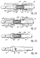
- les figures 2A à 2H sont des vues en coupe longitudinale illustrant schématiquement les principales étapes de mise en oeuvre du procédé de raccordement selon l'invention.
- Figure 1 is a partial longitudinal sectional view of an end element such as an electrical contact intended to be connected to the end of an electrical cable; and
- FIGS. 2A to 2H are views in longitudinal section schematically illustrating the main steps in implementing the connection method according to the invention.
Sur la figure 1, on a représenté un élément d'extrémité 10 tel qu'un contact électrique, avant son raccordement à l'extrémité d'un câble électrique 12 formé d'une âme 14 et d'une gaine isolante 16. L'âme 14 du câble 12 peut être réalisée en un métal quelconque, bien que l'invention s'applique avantageusement au cas où cette âme est réalisée en un métal léger tel que de l'aluminium. La gaine isolante 16 est réalisée en une matière plastique à haute performance mécanique et électrique. Elle recouvre l'âme 14 du câble 12, à l'exception de son extrémité qui est dénudée sur une longueur L prédéterminée.In Figure 1, there is shown an
L'élément d'extrémité 10 est réalisé en un matériau électriquement conducteur et possédant de bonnes aptitudes à la déformation à froid, tel qu'un alliage de cuivre.The
L'élément d'extrémité 10 présente une symétrie de révolution autour d'un axe longitudinal et comporte une partie avant normalisée 10a, strictement identique à la partie avant des contacts existants, ainsi qu'une partie arrière de raccordement 10b, dont la forme est modifiée conformément à l'invention.The
Dans le cas où l'élément d'extrémité est constitué par un contact électrique comme l'illustre la figure 1, la partie avant 10a est identique à celle des contacts mâles normalisés. Cependant, cette partie avant 10a peut prendre des formes et des dimensions diverses selon l'application envisagées. Ces formes peuvent notamment être celles d'un contact femelle ou d'un embout. Pour une raison qui apparaîtra par la suite, il est important d'observer que la partie avant 10a de l'élément d'extrémité 10 présente une collerette 18 qui définit un épaulement 20 tourné vers la partie arrière de raccordement 10b.In the case where the end element is constituted by an electrical contact as illustrated in FIG. 1, the
La partie arrière de raccordement 10b de l'élément d'extrémité 10, qui commence immédiatement en arrière de l'épaulement 20, présente une surface extérieure qui définit successivement, à partir de cet épaulement, une partie cylindrique 22, de diamètre uniforme, et une partie tronconique 24, dont le diamètre va en augmentant depuis la partie cylindrique 22 jusqu'à l'extrémité arrière de l'élément 10. Comme l'illustre la figure 1, la longueur de la partie tronconique 24 est sensiblement le double de la longueur de la partie cylindrique 22.The
De plus, un alésage borgne étagé 26 est formé coaxialement dans la partie arrière de raccordement 10b de l'élément d'extrémité 10 et s'étend jusqu'à l'intérieur de la collerette 18. En partant du fond, cet alésage 26 comporte un tronçon cylindrique de fond 26a, de relativement petit diamètre, un tronçon cylindrique intermédiaire 26b, dont le diamètre est légèrement supérieur à celui du tronçon de fond 26a et un tronçon cylindrique d'entrée 26c, dont le diamètre est légèrement supérieur à celui du tronçon intermédiaire 26b. A leur extrémité d'entrée, chacun des tronçons cylindriques 26a, 26b et 26c comporte un chanfrein 28a, 28b et 28c respectivement.In addition, a stepped blind bore 26 is formed coaxially in the
En dehors de son extrémité qui est située à l'intérieur de la collerette 18, le tronçon de fond 26a de l'alésage 26 est situé en totalité à l'intérieur de la partie cylindrique 22 de la surface extérieure de la partie arrière de raccordement 10b. Le tronçon intermédiaire 26b de l'alésage 26, dont la longueur est légèrement plus grande que celle du tronçon de fond 26a, est principalement situé à l'intérieur de la partie tronconique 24 de la surface extérieure de la partie arrière de raccordement 10b et se prolonge légèrement à l'intérieur de la partie cylindrique 22. Enfin, le tronçon d'entrée 26c de l'alésage 26 est totalement situé à l'intérieur de la partie tronconique 24 et présente une longueur inférieure à celle des tronçons cylindriques 26a et 26b.Apart from its end which is situated inside the
Par ailleurs, il est à noter que la longueur L de la partie dénudée du câble 12 est prédéterminée afin d'être légèrement supérieure à la longueur culée des tronçons 26a et 26b de l'alésage 26, mais sensiblement inférieure à la longueur totale de cet alésage 26.Furthermore, it should be noted that the length L of the stripped part of the
Le tronçon de fond 26a de l'alésage 26 présente un diamètre calibré égal au diamètre de l'âme 14 du câble 12, augmenté d'un léger jeu et de deux épaisseurs d'un manchon d'étanchéité transparent 30 prévu pour être monté légèrement à force dans ce tronçon de fond 26a. Le manchon d'étanchéité transparent 30 peut notamment être fabriqué à partir d'une gaine tubulaire en matière plastique extrudée, sectionnée à intervalles réguliers. Il présente une forme totalement symétrique, afin de pouvoir être monté dans le tronçon de fond 26a de l'alésage 26 sans avoir recours à un détrompage long et coûteux.The
Un trou de visite 32 est percé radialement dans la partie arrière de raccordement 10b de l'élément d'extrémité 10, de façon à déboucher sur la partie cylindrique 22 de la surface extérieure de cette partie arrière 10b et dans le tronçon de fond 26a de l'alésage 26. Ce trou de visite 32 facilite le traitement de la surface de l'alésage borgne 26, c'est-à-dire le dépôt éventuel de revêtements de protection sur cette surface ainsi que son rinçage. Il permet aussi de contrôler visuellement la présence de l'âme 14 du câble 12 lorsque le raccordement a été effectué.A
Le tronçon cylindrique intermédiaire 26b de l'alésage borgne 26 présente un diamètre calibré égal au diamètre de l'âme 14 du câble 12, augmenté d'un très léger jeu et de deux épaisseurs d'une bague d'interface 34. La bague d'interface 34 est prévue pour être montée légèrement à force dans le tronçon intermédiaire 26b de l'alésage 26. Elle est usinée dans un matériau hautement conducteur permettant d'améliorer le contact entre l'âme 14 du câble 12 (par exemple en aluminium) et l'élément d'extrémité 10 (par exemple en alliage de cuivre). La bague d'interface 34 permet aussi de compenser la différence de dilatation entre les matériaux constituant ces deux pièces (coefficient de dilatation d'environ 17 pour un alliage de cuivre et d'environ 23 pour un alliage d'aluminium). Pour remplir au mieux ces deux fonctions, la bague d'interface 34 est avantageusement réalisée en argent. En effet, la conductivité de l'argent est satisfaisante et son coefficient de dilatation est d'environ 19. De plus, il s'agit d'un métal facile à usiner et relativement malléable.The intermediate
Il est à noter que la présence de la bague d'interface 34 peut parfois être évitée. C'est notamment le cas lorsque l'âme 14 du câble 12 est également réalisée en un alliage de cuivre. C'est aussi le cas lorsque cette bague d'interface peut être remplacée par un dépôt métallique remplissant la même fonction à l'intérieur de l'alésage 26.It should be noted that the presence of the
Pour faciliter l'introduction du câble 14, la bague d'interface 34 présente à chacune de ses extrémités un chanfrein intérieur 36. Cette configuration symétrique de la bague d'interface 34 permet d'éviter d'avoir recours à un détrompage long et coûteux lors du montage.To facilitate the introduction of the
Les différentes étapes du raccordement du câble électrique 12 sur l'élément d'extrémité 10 vont à présent être décrites en se référant successivement aux figures 2A à 2H.The various stages of the connection of the
Dans un premier temps, on procède à un certain nombre de traitements de surface sur l'élément d'extrémité 10, selon des techniques habituelles. Ces traitements de surface comprennent le plus souvent un cuivrage de toutes les surfaces intérieures et extérieures de l'élément 10, facilitant l'adhérence des autres dépôts. Un nickelage peut aussi être effectué sur la partie avant 10a de l'élément 10. On peut en outre effectuer soit une dorure mince sur toutes les surfaces intérieures et extérieures de l'élément 10, soit une dorure sélective épaisse sur la partie avant 10a de cet élément. Enfin, comme on l'a déjà indiqué, un dépôt d'argent peut être fait à l'intérieur de l'alésage 26, notamment lorsqu'on désire se passer de la bague d'interface 34.Firstly, a number of surface treatments are carried out on the
Le trou de visite 32 rend possible l'échappement de l'air contenu dans l'alésage 26 lors du dépôt électrolytique et facilite les divers rinçages.The
Ensuite et comme l'illustre la figure 2A, le manchon d'étanchéité transparent 30 est monté légèrement à force dans le tronçon de fond 26a de l'alésage 26. Cette opération est facilitée par la présence du chanfrein 28a à l'entrée de ce tronçon 26a. Lorsqu'elle est terminée, le manchon d'étanchéité transparent 30 s'étend sur toute la longueur du tronçon de fond 26a et obture ainsi de façon étanche le trou de visite 32 (figure 2B).Then and as illustrated in FIG. 2A, the
La bague d'interface 34 est à son tour montée légèrement à force dans le tronçon intermédiaire 26b de l'alésage 26. Cette opération est facilitée par le chanfrein 28b qui se trouve à l'entrée du tronçon 26b. Lorsqu'elle est terminée, la bague d'interface 34 occupe toute la longueur du tronçon intermédiaire 26b.The
On introduit alors dans l'alésage 26, équipé du manchon 30 et de la bague 34, l'extrémité partiellement dénudée du câble 12, comme l'illustre la figure 2B. Etant donné que la longueur L de la partie dénudée du câble 12 est inférieure à la longueur totale de l'alésage 26 et à peine supérieure à la longueur cumulée des tronçons 26a et 26b de cet alésage, l'extrémité de la partie non dénudée du câble 12 se trouve située à l'intérieur du tronçon d'entrée 26c de l'alésage 26, à proximité du chanfrein 28b, lorsque l'extrémité du câble 10 est en butée dans le fond de cet alésage. Il est à noter que l'introduction du câble 10 est facilitée, pour son âme 14, par le chanfrein 36 formé à l'entrée de la bague d'interface 34 et, pour sa gaine 16, par le chanfrein 28c formé à l'entrée du tronçon d'entrée 26c de l'alésage 26. La pénétration de l'extrémité de l'âme 14 dans le manchon d'étanchéité transparent 30 ne pose pas de problème particulier, du fait que le diamètre intérieur de ce manchon est légèrement supérieur au diamètre intérieur de la bague d'interface 34. Elle est contrôlée visuellement, par le trou de visite 32, au travers du manchon transparent 30.Is then introduced into the
Comme l'illustre également la figure 2C, l'introduction de l'extrémité du câble 12 dans l'élément d'extrémité 10 est précédée ou suivie de la mise en place de l'élément d'extrémité 10 dans un outil de sertissage illustré de façon très schématique. Cet outil de sertissage comprend une pince 38 et une filière calibrée 40.As also illustrated in FIG. 2C, the introduction of the end of the
La pince 38 est formée d'au moins deux mors venant enserrer l'élément d'extrémité 10 autour de la partie cylindrique 22 de sa surface extérieure, de façon à pouvoir prendre appui sur l'épaulement 20, comme l'illustre la figure 2D.The
La filière 40 est également formée d'au moins deux demi-coquilles qui sont refermées sur la partie cylindrique 22 de la surface extérieure de l'élément d'extrémité 10, lorsque la pince 38 est fermée comme l'illustre la figure 2D.The
On compacte ensuite radialement la partie arrière de raccordement 10b de l'élément d'extrémité 10 par tréfilage, de la manière illustrée sur les figures 2E et 2F. Comme l'illustrent les flèches F sur ces figures, cette opération de tréfilage ou de sertissage est effectuée en exerçant un effort de traction sur l'élément d'extrémité 10, selon son axe, au moyen de la pince 38, de façon à faire passer sur toute sa longueur la partie arrière de raccordement 10b au travers de la filière calibrée 40. Cette opération a pour conséquence de transformer la surface extérieure de la partie arrière de raccordement 10b en une surface cylindrique, dont le diamètre uniforme est sensiblement égal au diamètre initial de la partie cylindrique 22.The
On donne ainsi au tronçon intermédiaire 26b et au tronçon d'entrée 26c de l'alésage 26 des formes tronconiques dont le diamètre va en diminuant vers l'extrémité ouverte de l'alésage 26. La déformation du tronçon intermédiaire 26b de l'alésage a pour conséquence une déformation analogue de la bague d'interface 34.The
Par conséquent, et comme l'illustre la figure 2G, lorsque cette opération de tréfilage est terminée, il existe une liaison mécanique à la fois entre l'élément d'extrémité 10 et l'âme 14 du câble 12 et entre l'élément d'extrémité 10 et la gaine 16 de ce câble. Cette liaison mécanique s'oppose à tout arrachement accidentel de l'élément d'extrémité et assure une tenue mécanique suffisante lorsque l'âme 14 du câble 12 est de petit diamètre et formée d'un métal léger tel que de l'aluminium. En outre, la liaison mécanique obtenue entre l'élément d'extrémité 10 et la gaine 16 du câble 12 assure l'étanchéité du raccordement, conjointement avec le manchon d'étanchéité transparent 30 au droit du trou de visite 32 (figure 2H).Consequently, and as illustrated in FIG. 2G, when this drawing operation is finished, there is a mechanical connection both between the
On réalise ainsi une connexion particulièrement adaptée à l'utilisation d'un câble à âme en aluminium mais dont l'étanchéité et le caractère non agressif permettent d'envisager son application dans le cas d'un câble dont l'âme est réalisée en tout autre matériau et notamment en cuivre.A connection is thus made which is particularly suitable for the use of a cable with an aluminum core but whose tightness and non-aggressive nature make it possible to envisage its application in the case of a cable whose core is made in all other material including copper.
Claims (10)
- Process for the connection of an electric cable (12) to an end member (10), whose rear connection portion (10b) has a blind hole (26) and an outer surface having at least one truncated cone-shaped portion (24), whose diameter increases towards an open end of the hole, in which: the cable (12) is introduced into the blind hole (26) and the rear connection portion (10b) is radially compacted to give the outer surface a cylindrical shape, characterized in that:- use is made of a cable (12) having a core (14) covered with an insulating sheath (16),- the cable is bared over a length smaller than that of the blind hole (26),- the cable is introduced into a stepped blind hole (26) formed from at least two cylindrical sections (26a, 26b, 26c), each having a chamfered entrance end (28a, 28b, 28c), so that an unbared portion of the cable is received in an entrance section (26e) of the hole, the truncated cone-shaped portion (24) of the outer surface being located around the entrance section (26c) and at least one other section of the hole (26) and- radial compaction takes place of the rear connection portion of the end member (10) by wiredrawing, whilst exerting a tension on said member, so as to pass the rear connection portion into a calibrated die (40).
- Process according to claim 1, characterized in that use is made of an end member (10) having at least one inspection hole (32) issuing into a bottom section (26a) of the blind hole and, before introducing the cable (12) into said blind hole, a transparent sealling sleeve (30) is placed in the bottom section.
- Process according to claim 2, characterized in that use is made of the inspection hole (32) for facilitating the treatment of the interior of the blind hole (26), prior to the positioning there of the transparent sealing sleeve (30).
- Process according to either of the claims 2 and 3, characterized in that, after placing the transparent sealing sleeve (30) in the bottom section (26a) and before introducing the cable (12) into the blind hole (26), an interface ring (34) made from an electrically conductive material is placed in an intermediate section (26b) of the blind hole.
- Process according to claim 4, characterized in that use is made of an interface ring (34), chamfered towards the inside at its ends.
- End member fitted, by radial compacting, onto the end of an electric cable (12), said member having a front portion (10a) and a rear connection portion (10b), the latter having a blind hole (26) receiving one end of the cable, and an outer surface having at least one truncated cone-shaped portion (24), whose diameter increases towards an open end of the blind hole, characterized in that the end member is to be fitted onto the end of a cable (12) having a core (14) covered with an insulating sheath (16) and bared over a length smaller than that of the blind hole (26), the latter being stepped and formed from at least two cylindrical sections (26a, 26b, 26e) of the hole receiving an unbared portion of the cable, the truncated cone-shaped portion (24) of the outer surface being located around the entrance section and at least one other section of the hole, and the front portion (10a) has a shoulder (20) turned towards the rear connection portion (10b) and able to serve as an anchoring means for the tension device for the radial compacting of the rear connection portion by wiredrawing.
- End member according to claim 6, characterized in that at least one inspection hole (32) issues into a bottom section (26a) of the blind hole and a transparent sealing sleeve (30) is placed in said bottom section.
- End member according to claim 7, characterized in that the blind hole also has an intermediate section (26b) in which is placed an interface ring (34) made from an electrically conductive material.
- End member according to claim 8, characterized in that the ends of the interface ring (34) are chamfered towards the inside and the internal diameter of said ring is slightly smaller than the internal diameter of the transparent sealing sleeve (30).
- End member according to either of the claims 8 and 9, characterized in that the outer surface has a cylindrical portion (22) mainly surrounding the bottom section (26a) of the hole and a truncated cone-shaped portion (24) mainly surrounding the intermediate section and entrance section of the hole.
Applications Claiming Priority (2)
| Application Number | Priority Date | Filing Date | Title |
|---|---|---|---|
| FR9308818 | 1993-07-19 | ||
| FR9308818A FR2708150B1 (en) | 1993-07-19 | 1993-07-19 | Method for connecting an electric cable to an end element and corresponding end element. |
Publications (2)
| Publication Number | Publication Date |
|---|---|
| EP0635901A1 EP0635901A1 (en) | 1995-01-25 |
| EP0635901B1 true EP0635901B1 (en) | 1997-10-08 |
Family
ID=9449349
Family Applications (1)
| Application Number | Title | Priority Date | Filing Date |
|---|---|---|---|
| EP94401639A Expired - Lifetime EP0635901B1 (en) | 1993-07-19 | 1994-07-18 | Process for connecting an electric cable to a terminal element and correspondant terminal element |
Country Status (6)
| Country | Link |
|---|---|
| US (1) | US5499448A (en) |
| EP (1) | EP0635901B1 (en) |
| CA (1) | CA2127913C (en) |
| DE (1) | DE69406065T2 (en) |
| ES (1) | ES2110196T3 (en) |
| FR (1) | FR2708150B1 (en) |
Cited By (1)
| Publication number | Priority date | Publication date | Assignee | Title |
|---|---|---|---|---|
| EP2273618A1 (en) * | 2009-07-08 | 2011-01-12 | Mecatraction | Crimping connection device for electrical cable and method for producing a such device |
Families Citing this family (35)
| Publication number | Priority date | Publication date | Assignee | Title |
|---|---|---|---|---|
| EP0966061B1 (en) * | 1998-06-16 | 2004-01-14 | Kabelkonfektion Gebauer & Griller Gmbh | Method for the electrical and mechanical connection of electrically conductive parts and device for carrying out this method |
| DE19843886A1 (en) * | 1998-09-24 | 2000-03-30 | Grote & Hartmann | Cable shoe for electrical conductor wire or cable, has termination sleeve receiving stripped end of conductor wire or cable enclosed coaxially by reinforcing sleeve |
| US6453551B1 (en) * | 2000-06-02 | 2002-09-24 | Thaddeus E. Nordquist | Manufacture for feed-through devices |
| EP1191632B1 (en) * | 2000-09-21 | 2005-12-21 | Yazaki Corporation | Structure and method for connecting terminal and electric wire |
| JP2002124310A (en) * | 2000-10-13 | 2002-04-26 | Yazaki Corp | Terminal-mounting structure and terminal-mounting method for coated wire |
| JP2002216862A (en) * | 2001-01-19 | 2002-08-02 | Yazaki Corp | Waterproof structure of connection part of electric wire and terminal, and waterproofing method |
| US6739899B2 (en) * | 2001-07-25 | 2004-05-25 | Yazaki Corporation | Method and structure for connecting a terminal with a wire |
| US6805596B2 (en) * | 2002-04-16 | 2004-10-19 | Alcoa Fujikura Limited | Compression formed connector for a composite conductor assembly used in transmission line installations and method of constructing the same |
| JP4422391B2 (en) * | 2002-08-07 | 2010-02-24 | 矢崎総業株式会社 | How to connect wires and terminals |
| JP2005050736A (en) * | 2003-07-30 | 2005-02-24 | Furukawa Electric Co Ltd:The | Method of manufacturing terminal crimping structure to aluminum wire and aluminum wire with terminal |
| EP1503454B1 (en) * | 2003-07-30 | 2015-08-05 | Furukawa Electric Co. Ltd. | Terminal crimping structure for aluminium wire and producing method |
| US20070119562A1 (en) * | 2004-04-14 | 2007-05-31 | Gregory George R | System and method for termination of a wire rope |
| US7231957B2 (en) * | 2004-04-14 | 2007-06-19 | George Robert Gregory | System and method for termination of a wire rope |
| FR2873504B1 (en) | 2004-07-26 | 2007-04-13 | Airbus France Sas | TOOL AND METHOD FOR CRIMPING A CONTACT ON A CABLE |
| US7896712B2 (en) * | 2005-12-22 | 2011-03-01 | Tensolite, Llc | Integral bonding attachment |
| DE102007015696A1 (en) * | 2007-03-31 | 2008-10-02 | Gustav Klauke Gmbh | Cable socket for electrical conductor, has flat-connecting section, and plug-in section with two partial sections, of which one has diameter larger than other and include control opening |
| US7695331B2 (en) * | 2007-05-01 | 2010-04-13 | Tri-Star Technology | Electrical contact assembly including a sleeve member |
| US7611392B2 (en) * | 2007-09-17 | 2009-11-03 | Thomas & Betts International, Inc. | Terminal with integral strain relief |
| JP5079605B2 (en) * | 2008-06-30 | 2012-11-21 | 株式会社オートネットワーク技術研究所 | Crimp terminal, electric wire with terminal, and manufacturing method thereof |
| FR2935202B1 (en) * | 2008-08-21 | 2010-10-22 | Labinal | DEVICE FOR CONNECTION BETWEEN AN ELECTRICAL CABLE AND A CONDUCTIVE STRUCTURE, IN PARTICULAR FOR A CURRENT RETURN CIRCUIT |
| US9385449B2 (en) * | 2009-02-16 | 2016-07-05 | Carlisle Interconnect Technologies, Inc. | Terminal/connector having integral oxide breaker element |
| JP5557377B2 (en) * | 2010-03-23 | 2014-07-23 | 矢崎総業株式会社 | Connection structure for terminal wires |
| EP2511983B1 (en) * | 2011-04-12 | 2016-03-23 | Nexans | Cable lug |
| CN102931499B (en) * | 2011-08-11 | 2015-07-08 | 泰科电子(上海)有限公司 | Electric connection assembly |
| US8845361B2 (en) * | 2011-11-08 | 2014-09-30 | Thomas & Betts International Llc | Explosion-proof electrical fitting |
| US10468785B1 (en) * | 2014-11-26 | 2019-11-05 | The National Telephone Supply Company | Crimp sleeve |
| US9985362B2 (en) | 2015-10-22 | 2018-05-29 | Carlisle Interconnect Technologies, Inc. | Arc resistant power terminal |
| JP6610392B2 (en) * | 2016-04-07 | 2019-11-27 | 住友電装株式会社 | Conductor connection structure and wire harness |
| DE102017105682A1 (en) * | 2017-03-16 | 2018-09-20 | Te Connectivity Germany Gmbh | Contact carrier, electrical contact device and method for producing a ready-made cable |
| DE102017114994B3 (en) * | 2017-07-05 | 2018-05-09 | Lisa Dräxlmaier GmbH | METHOD FOR MANUFACTURING AN ELECTRICAL LINE ASSEMBLY |
| GB201808026D0 (en) | 2018-05-17 | 2018-07-04 | Hubbell Ltd | Cable gland |
| US11476595B2 (en) * | 2018-11-07 | 2022-10-18 | Ls Cable & System Ltd. | Power cable intermediate connection structure |
| US10923848B2 (en) * | 2018-12-14 | 2021-02-16 | Carlisle Interconnect Technologies, Inc. | Modular barrel contact system for electrical connectors |
| DE102020119423A1 (en) * | 2020-07-23 | 2022-01-27 | Md Elektronik Gmbh | Soldering aid and method for attaching a cable to a conductor surface |
| DE102022100191A1 (en) * | 2022-01-05 | 2023-07-06 | EngstKabel GmbH & Co. KG | Improved conductive sleeve and method of connecting a section of conductor to the conductive sleeve |
Family Cites Families (7)
| Publication number | Priority date | Publication date | Assignee | Title |
|---|---|---|---|---|
| US2297785A (en) * | 1941-09-13 | 1942-10-06 | Ibm | Terminal for electrical conductors |
| US2803695A (en) * | 1951-05-03 | 1957-08-20 | Amp Inc | Closed end connector |
| US3010184A (en) * | 1958-11-13 | 1961-11-28 | Amp Inc | Method of making an electrical connection |
| FR1260806A (en) * | 1960-03-31 | 1961-05-12 | Materiel Electr Soc Ind De | Improvement of sleeve crimping processes on metal cables |
| GB954409A (en) * | 1962-01-09 | 1964-04-08 | Cable Covers Ltd | Compression connectors for joining or terminating wires, rods and other suitable members |
| DE2544927A1 (en) * | 1975-10-07 | 1977-04-21 | Roesler Karl Heinz | Cable shoe for battery charge cable - has holding and sealing element in cable shoe bore engageable by end section insulation |
| FR2613541B1 (en) * | 1987-04-06 | 1990-04-06 | Labinal | PROCESS FOR PRODUCING LEAD TERMINALS OR THE LIKE ON ALUMINUM CABLES |
-
1993
- 1993-07-19 FR FR9308818A patent/FR2708150B1/en not_active Expired - Fee Related
-
1994
- 1994-07-13 CA CA002127913A patent/CA2127913C/en not_active Expired - Fee Related
- 1994-07-15 US US08/275,953 patent/US5499448A/en not_active Expired - Lifetime
- 1994-07-18 EP EP94401639A patent/EP0635901B1/en not_active Expired - Lifetime
- 1994-07-18 DE DE69406065T patent/DE69406065T2/en not_active Expired - Lifetime
- 1994-07-18 ES ES94401639T patent/ES2110196T3/en not_active Expired - Lifetime
Cited By (2)
| Publication number | Priority date | Publication date | Assignee | Title |
|---|---|---|---|---|
| EP2273618A1 (en) * | 2009-07-08 | 2011-01-12 | Mecatraction | Crimping connection device for electrical cable and method for producing a such device |
| FR2947960A1 (en) * | 2009-07-08 | 2011-01-14 | Mecatraction | CRUSHING CONNECTING DEVICE FOR ELECTRIC CABLE AND METHOD OF MANUFACTURING SUCH A DEVICE |
Also Published As
| Publication number | Publication date |
|---|---|
| CA2127913A1 (en) | 1995-01-20 |
| DE69406065T2 (en) | 1998-04-09 |
| ES2110196T3 (en) | 1998-02-01 |
| DE69406065D1 (en) | 1997-11-13 |
| EP0635901A1 (en) | 1995-01-25 |
| FR2708150A1 (en) | 1995-01-27 |
| CA2127913C (en) | 2005-10-25 |
| FR2708150B1 (en) | 1995-10-13 |
| US5499448A (en) | 1996-03-19 |
Similar Documents
| Publication | Publication Date | Title |
|---|---|---|
| EP0635901B1 (en) | Process for connecting an electric cable to a terminal element and correspondant terminal element | |
| EP0576666B1 (en) | Method for connecting an electrical cable with a light metal conductor to a standardized terminating element, and connecting member therefor | |
| FR2500638A1 (en) | OPTICAL FIBER CABLE | |
| EP2273618A1 (en) | Crimping connection device for electrical cable and method for producing a such device | |
| FR3057717A1 (en) | UNDERWATER ELECTRICAL CONNECTION SYSTEM | |
| EP3591763A1 (en) | Connection method for connecting an insulated micro-conductor | |
| FR3070798A1 (en) | CABLE CONNECTION AND CABLE CONNECTION METHOD | |
| EP0154588B1 (en) | Process of carrying out dismountable joints and ensuring a fluid-tight seal to high-pressure pipes and related pipe joints | |
| EP1469560A1 (en) | Contact piece for an electrical connector | |
| EP1383211B1 (en) | Method for crimping a contact to strands of a cable | |
| FR2667449A1 (en) | CONNECTOR FOR SHIELDED COAXIAL CABLE. | |
| FR2475306A1 (en) | UNIVERSAL JUNCTION BOX FOR TELECOMMUNICATIONS OR POWER CABLES | |
| CA2434592A1 (en) | Connecting device between a cable and a contact element | |
| FR2633103A1 (en) | WIRING TOE | |
| FR2853151A1 (en) | METHOD FOR SEALING A MULTI-STRAND GROUNDING CABLE | |
| EP3118932B1 (en) | Electrical connecting member for electrical wiring elements | |
| EP0016715B1 (en) | Sealing device and process for tightly fitting a sleeve to an insulated electrical conductor or to a pipe, and method of manufacturing it | |
| FR2884974A1 (en) | Electric connector for connecting e.g. male contact on conducting cable, has standard end unit connected to end of cable and inserted via opening of tang into clip until complete engagement of end unit in retention component of clip | |
| FR2497392A1 (en) | ELECTRO-TRACTOR CABLE | |
| FR3061810A1 (en) | DEVICE FOR CONNECTION BETWEEN THE SCREENS OF TWO ELECTRIC CABLE ELEMENTS | |
| EP3067991A1 (en) | Female contact comprising a spring | |
| EP3062407B1 (en) | Coupling sleeve between conductive cables, manufacturing process and implementing process for such a sleeve. | |
| FR2683396A1 (en) | Electrical contact for an electrical cable having an aluminium core and electrical connector equipped with at least one such contact | |
| FR2475304A1 (en) | Cable end sleeve with electrolytic corrosion protection - has matching liner inserted within tube with end deformed by pressing metal sleeve onto it | |
| FR2546680A1 (en) | Process for manufacturing a through-cable anchoring sleeve for a bare electrical conductor, and sleeve thus obtained |
Legal Events
| Date | Code | Title | Description |
|---|---|---|---|
| PUAI | Public reference made under article 153(3) epc to a published international application that has entered the european phase |
Free format text: ORIGINAL CODE: 0009012 |
|
| AK | Designated contracting states |
Kind code of ref document: A1 Designated state(s): DE ES GB IT NL |
|
| 17P | Request for examination filed |
Effective date: 19950629 |
|
| 17Q | First examination report despatched |
Effective date: 19960502 |
|
| GRAG | Despatch of communication of intention to grant |
Free format text: ORIGINAL CODE: EPIDOS AGRA |
|
| GRAH | Despatch of communication of intention to grant a patent |
Free format text: ORIGINAL CODE: EPIDOS IGRA |
|
| GRAH | Despatch of communication of intention to grant a patent |
Free format text: ORIGINAL CODE: EPIDOS IGRA |
|
| GRAA | (expected) grant |
Free format text: ORIGINAL CODE: 0009210 |
|
| AK | Designated contracting states |
Kind code of ref document: B1 Designated state(s): DE ES GB IT NL |
|
| REF | Corresponds to: |
Ref document number: 69406065 Country of ref document: DE Date of ref document: 19971113 |
|
| ITF | It: translation for a ep patent filed |
Owner name: PROPRIA PROTEZIONE PROPR. IND. |
|
| GBT | Gb: translation of ep patent filed (gb section 77(6)(a)/1977) |
Effective date: 19971212 |
|
| REG | Reference to a national code |
Ref country code: ES Ref legal event code: FG2A Ref document number: 2110196 Country of ref document: ES Kind code of ref document: T3 |
|
| PLBE | No opposition filed within time limit |
Free format text: ORIGINAL CODE: 0009261 |
|
| STAA | Information on the status of an ep patent application or granted ep patent |
Free format text: STATUS: NO OPPOSITION FILED WITHIN TIME LIMIT |
|
| 26N | No opposition filed | ||
| REG | Reference to a national code |
Ref country code: GB Ref legal event code: IF02 |
|
| PGFP | Annual fee paid to national office [announced via postgrant information from national office to epo] |
Ref country code: ES Payment date: 20090724 Year of fee payment: 16 |
|
| PGFP | Annual fee paid to national office [announced via postgrant information from national office to epo] |
Ref country code: NL Payment date: 20090730 Year of fee payment: 16 |
|
| PGFP | Annual fee paid to national office [announced via postgrant information from national office to epo] |
Ref country code: IT Payment date: 20100726 Year of fee payment: 17 Ref country code: DE Payment date: 20100723 Year of fee payment: 17 |
|
| PGFP | Annual fee paid to national office [announced via postgrant information from national office to epo] |
Ref country code: GB Payment date: 20100722 Year of fee payment: 17 |
|
| REG | Reference to a national code |
Ref country code: NL Ref legal event code: V1 Effective date: 20110201 |
|
| PG25 | Lapsed in a contracting state [announced via postgrant information from national office to epo] |
Ref country code: NL Free format text: LAPSE BECAUSE OF NON-PAYMENT OF DUE FEES Effective date: 20110201 |
|
| REG | Reference to a national code |
Ref country code: ES Ref legal event code: FD2A Effective date: 20110818 |
|
| PG25 | Lapsed in a contracting state [announced via postgrant information from national office to epo] |
Ref country code: ES Free format text: LAPSE BECAUSE OF NON-PAYMENT OF DUE FEES Effective date: 20100719 |
|
| GBPC | Gb: european patent ceased through non-payment of renewal fee |
Effective date: 20110718 |
|
| PG25 | Lapsed in a contracting state [announced via postgrant information from national office to epo] |
Ref country code: DE Free format text: LAPSE BECAUSE OF NON-PAYMENT OF DUE FEES Effective date: 20120201 |
|
| REG | Reference to a national code |
Ref country code: DE Ref legal event code: R119 Ref document number: 69406065 Country of ref document: DE Effective date: 20120201 |
|
| PG25 | Lapsed in a contracting state [announced via postgrant information from national office to epo] |
Ref country code: IT Free format text: LAPSE BECAUSE OF NON-PAYMENT OF DUE FEES Effective date: 20110718 |
|
| PG25 | Lapsed in a contracting state [announced via postgrant information from national office to epo] |
Ref country code: GB Free format text: LAPSE BECAUSE OF NON-PAYMENT OF DUE FEES Effective date: 20110718 |