EP0635823B1 - Rotary transformer - Google Patents
Rotary transformer Download PDFInfo
- Publication number
- EP0635823B1 EP0635823B1 EP19940111194 EP94111194A EP0635823B1 EP 0635823 B1 EP0635823 B1 EP 0635823B1 EP 19940111194 EP19940111194 EP 19940111194 EP 94111194 A EP94111194 A EP 94111194A EP 0635823 B1 EP0635823 B1 EP 0635823B1
- Authority
- EP
- European Patent Office
- Prior art keywords
- rotary
- magnetic member
- coils
- stationary
- coil
- Prior art date
- Legal status (The legal status is an assumption and is not a legal conclusion. Google has not performed a legal analysis and makes no representation as to the accuracy of the status listed.)
- Expired - Lifetime
Links
Images


Classifications
-
- G—PHYSICS
- G11—INFORMATION STORAGE
- G11B—INFORMATION STORAGE BASED ON RELATIVE MOVEMENT BETWEEN RECORD CARRIER AND TRANSDUCER
- G11B5/00—Recording by magnetisation or demagnetisation of a record carrier; Reproducing by magnetic means; Record carriers therefor
- G11B5/48—Disposition or mounting of heads or head supports relative to record carriers ; arrangements of heads, e.g. for scanning the record carrier to increase the relative speed
- G11B5/52—Disposition or mounting of heads or head supports relative to record carriers ; arrangements of heads, e.g. for scanning the record carrier to increase the relative speed with simultaneous movement of head and record carrier, e.g. rotation of head
- G11B5/53—Disposition or mounting of heads on rotating support
- G11B5/531—Disposition of more than one recording or reproducing head on support rotating cyclically around an axis
-
- H—ELECTRICITY
- H01—ELECTRIC ELEMENTS
- H01F—MAGNETS; INDUCTANCES; TRANSFORMERS; SELECTION OF MATERIALS FOR THEIR MAGNETIC PROPERTIES
- H01F38/00—Adaptations of transformers or inductances for specific applications or functions
- H01F38/18—Rotary transformers
Definitions
- the present invention relates to a rotary transformer in accordance with the precharacterizing part of claim 1.
- a rotary transformer is included in a rotary magnetic head device used in a magnetic recording/reproducing apparatus such as a video tape recorder, and more particularly, to a rotary transformer which can reduce crosstalk of a rotary magnetic head device also in a high frequency region.
- a rotary transformer of this type is, for example, known from Patent Abstracts of Japan, vol 8, no: 139, (E-253 ), 28.06.1984 corresponding to JP-A-59 048 906.
- a rotary transformer transferring a signal between a rotary magnetic head unit and a stationary signal processing unit tends to include multiple channels. It is desired that crosstalk of a record/reproduction signal between channels of such a rotary transformer is reduced even in a high frequency region.
- Fig. 15 is a vertical sectional view of a conventional cylinder type rotary transformer.
- Fig. 16 is a vertical sectional view of a conventional disc type rotary transformer.
- Each of these rotary transformers includes a rotary magnetic member 1a and a stationary magnetic member 1b.
- Rotary magnetic member 1a is coupled to a rotary drum (not shown in Figs. 15 and 16) disposed thereabove, and stationary magnetic member 1b is fixed to a stationary drum (not shown in Figs. 15 and 16) disposed thereunder.
- a through hole 7 provided along the center axis of these two magnetic members 1a, 1b receives a rotary axis for a rotary drum.
- Rotary magnetic member 1a and stationary magnetic member 1b have respective counter surfaces opposing to each other with a small space interposed therebetween.
- a plurality of rotary coil grooves 2a are formed on the counter surface of rotary magnetic member 1a
- a plurality of stationary coil grooves 2b are formed on the counter surface of stationary magnetic member 1b.
- Each of the plurality of rotary coil grooves 2a is opposed to a corresponding one of the plurality of stationary coil grooves 2b.
- Signal transfer rotary coils 3a and 4a are disposed in corresponding rotary coil groove 2a.
- signal transfer stationary coils 3b and 4b are disposed in corresponding stationary coil groove 2b.
- Lead lines 3A and 4A from rotary coils 3a and 4a are drawn out upward through a wiring groove 8a provided in the direction orthogonal to coil groove 2a on the counter surface of rotary magnetic member 1a toward the rotary drum.
- Lead lines 3B and 4B from stationary coils 4a and 4b are drawn out downward through a wiring groove 8b provided in the direction orthogonal to stationary groove 2b on the counter surface of stationary magnetic member 1b toward the stationary signal processing unit.
- Figs. 15 and 16 the counter surface of rotary magnetic member 1a and the counter surface of stationary magnetic member 1b are opposed to each other with a small space S of several ten ⁇ m interposed therebetween.
- record/reproduction signals are transferred between rotary coil 3a and stationary coil 3b, and between rotary coil 4a and stationary coil 4b.
- reproduction signal current flows from the rotary magnetic head to rotary coil 3a, for example, magnetic paths 5a, 5b as shown by dotted lines are formed, and current is induced in stationary coil 3b by the mutual dielectric reaction.
- a reproduction signal is to be transferred from rotary coil 3a to stationary coil 3b.
- signal transfer from stationary coil 3b to rotary coil 3a, signal transfer from rotary coil 4a to stationary coil 4b, and signal transfer from stationary coil 4b to rotary coil 4a are carried out by the mutual dielectric reaction.
- a short-circuited rotary coil ring 6a is disposed in rotary groove 2a between two signal transfer rotary coils 3a and 4a.
- a short-circuited stationary coil ring 6b is disposed in stationary groove 2b between two signal transfer stationary coils 3b and 4b.
- These coil rings 6a and 6b are generally provided for reduction of crosstalk caused by magnetic field coupling.
- coil rings 6a, 6b produce eddy current to reduce magnetic flux in magnetic path 5b, thereby reducing crosstalk to signal transfer stationary coil 4b.
- a rotary transformer is now desired which can transfer even a high frequency region of a record/reproduction signal with a high fidelity.
- Crosstalk in a high frequency region caused by electric field coupling can no longer be ignored.
- Coil rings 6a, 6b as described above can reduce crosstalk caused by magnetic field coupling, but can not reduce crosstalk caused by electric field coupling.
- a high-frequency loss caused by distributed capacity of coils in a rotary transformer has a large influence on crosstalk caused by electric field coupling.
- crosstalk caused by electric field coupling.
- JP-A-2-214109 discloses an example of a rotary transformer which can reduce such crosstalk caused by electric field coupling.
- This rotary transformer requires a through hole from a coil groove provided on a counter surface of a magnetic member to the surface opposite to the counter surface. Lead lines from a coil are drawn out to the surface opposite to the counter surface of the magnetic member through the through hole. More specifically, in the rotary transformer disclosed in JP-A-2-214109, a plurality of lead lines of a plurality of coils must be passed through a corresponding plurality of small through holes provided in the magnetic member, complicating the manufacturing process of the rotary transformer.
- JP-A-5-67529 a rotary transformer reducing crosstalk caused by electric coupling is disclosed.
- a first conductive member is disposed close to a rotary magnetic member.
- the rotary magnetic member is electrically connected to the ground potential through the first conductive member.
- a second conductive member is disposed close to a stationary magnetic member, which is electrically connected to the ground potential through the second conductive member.
- only a connection of the rotary magnetic member and the stationary magnetic member with the ground potential cannot sufficiently reduce crosstalk in a high frequency region.
- one object of the present invention is to provide a rotary transformer which can reduce not only crosstalk caused by magnetic field coupling but also crosstalk in a high frequency region caused by electric field coupling, and which can be easily fabricated.
- a rotary transformer comprising a rotary magnetic member, a stationary magnetic member ,and two pairs of coils, said two magnetic members having respective counter surfaces opposing to each other with a small space interposed therebetween, wherein
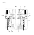
- Fig. 1 is a vertical sectional view of a rotary magnetic head device including a cylinder type rotary transformer according to one embodiment of the present invention.
- Fig. 2 is an enlarged vertical sectional view of a cylinder type rotary transformer included in the rotary magnetic head device of Fig. 1.
- Fig. 3 is a vertical sectional view of a disc type rotary transformer according to another embodiment of the present invention.
- Fig. 4 is an elevational view showing a rotary magnetic member and a plurality of coils of the cylinder type rotary transformer shown in Fig. 2.
- Fig. 5 is a vertical sectional view showing a stationary magnetic member and a plurality of coils of the cylinder type rotary transformer shown in Fig. 2.
- Fig. 6 is a bottom view showing a rotary magnetic member and a plurality of coils of the disc type rotary transformer shown in Fig. 3.
- Fig. 7 is a vertical sectional view showing a cylinder type rotary transformer according to still another embodiment of the present invention.
- Fig. 8 is a vertical sectional view showing a disc type rotary transformer according to a further embodiment of the present invention.
- Fig. 9 is a vertical sectional view showing a cylinder type rotary transformer according to a further embodiment of the present invention.
- Fig. 10 is a vertical sectional view showing a disc type rotary transformer according to a further embodiment of the present invention.
- Fig. 11 is a vertical sectional view showing a cylinder type rotary transformer according to a further embodiment of the present invention.
- Fig. 12 is a vertical sectional view showing a disc type rotary transformer according to a further embodiment of the present invention.
- Fig. 13 is a graph showing crosstalk characteristics in rotary transformers according to various embodiments of the present invention.
- Fig. 14 is a graph showing an influence of a distance between a magnetic member and a conductive member on a crosstalk characteristic in the rotary transformer shown in Fig. 7.
- Fig. 15 is a vertical sectional view showing a conventional cylinder type rotary transformer.
- Fig. 16 is a vertical sectional view showing a conventional disc type rotary transformer.
- Fig. 1 shows a rotary magnetic head device including a cylinder type rotary transformer according to one embodiment of the present invention.
- the rotary magnetic head device includes a rotary magnetic member 11a and a stationary magnetic member 11b included in a rotary transformer, a stationary drum 33, a rotary drum 34, a pair of magnetic heads 35a and 35b, a stationary axis 36, a rotary bearing 37, a motor stator 38, and a motor rotor 39.
- FIG. 2 shows an enlarged vertical section of the rotary transformer included in the rotary magnetic head device of Fig. 1.
- Fig. 3 shows a vertical section of a disc type rotary transformer according to another embodiment of the present invention.
- Each of rotary transformers shown in Figs. 2 and 3 includes rotary magnetic member 11a coupled to a rotary drum, and stationary magnetic member 11b attached to a stationary drum.
- a through hole 17 provided along the center axis of rotary magnetic member 11a and stationary magnetic member 11b receives a rotary axis for the rotary drum.
- Rotary magnetic member 11a and stationary magnetic member 11b have respective counter surfaces opposing to each other with a small space S interposed therebetween.
- a plurality of coil grooves 12a and 12b are formed on corresponding respective counter surfaces.
- a plurality of signal transfer rotary coils 13a and 14a are disposed in the plurality of rotary coil grooves 12a on rotary magnetic member 11a.
- signal transfer stationary coils 3b and 4b are disposed in the plurality of stationary coil grooves 12b on stationary magnetic member 11b.
- Figs. 4 and 5 are an elevational view showing the counter surface of rotary magnetic member 11a and a vertical sectional view showing the counter surface of stationary magnetic member 11b, respectively, in the cylinder type rotary transformer shown in Fig. 2.
- Fig. 6 is a bottom view showing the counter surface of rotary magnetic member 11a in the disc type rotary transformer shown in Fig. 3.
- a short-circuited rotary coil ring 16a is disposed in rotary coil groove 12a between signal transfer rotary coils 13a and 14a.
- a short-circuited stationary coil ring 16b is provided in stationary coil groove 12b provided between signal transfer stationary coils 13b and 14b.
- rotary magnetic member 11a in the cylinder type rotary transformer is provided with two wiring grooves 18a in the direction orthogonal to the plurality of rotary coil grooves 12a on the counter surface. These two wiring grooves 18a are disposed in symmetry with respect to the center axis of rotary magnetic member 11a.
- a pair of lead lines 13A from signal transfer rotary coil 13a on the upper side are drawn out upward through one wiring groove 18a toward the rotary magnetic head.
- a pair of lead lines 14A from rotary coil 14a on the lower side are once drawn out downward through the other wiring groove 18a, folded at a lower end portion of rotary magnetic member 11a, and then drawn out upward through a groove provided along the inner peripheral surface toward the rotary magnetic head.
- stationary magnetic member 11b of the cylinder type rotary transformer is provided with two wiring grooves 18b in the direction orthogonal to the plurality of stationary coil grooves 12b. These two wiring grooves 18b are disposed in symmetry with respect to the center axis of stationary magnetic member 11b.
- a pair of lead lines 14B from signal transfer stationary coil 14b on the lower side are drawn out downward through one wiring groove 18b toward the stationary signal processing unit.
- a pair of lead lines 13B from signal transfer stationary coil 13b on the upper side are once drawn out upward, folded at an upper end portion of stationary magnetic member 11b, and then drawn out downward through a groove provided along the outer peripheral surface toward the stationary signal processing unit.
- a pair of lead lines 13A from signal transfer rotary coil 13a on the outer side are drawn out upward through wiring groove 18a and a notched grooved 19a provided along the outer peripheral end surface of rotary magnetic member 11a toward the rotary magnetic head.
- a pair of lead lines 14A from signal transfer rotary coil 14a on the inner side are drawn out upward through wiring groove 18a and a notched groove 19b provided along the inner peripheral end surface of rotary magnetic member 11a toward the rotary magnetic head.
- a pair of lead lines 13B from signal transfer stationary coil 13b on the outer side are drawn out downward through wiring groove 18b and notched groove 19a provided along the outer peripheral end surface of stationary magnetic member 11b toward the stationary signal processing unit.
- a pair of lead lines 14B from signal transfer stationary coil 14b on the inner side are drawn out downward through wiring groove 18b and notched groove 19b provided along the inner peripheral end surface of stationary magnetic member 11b toward the stationary signal processing unit.
- Figs. 7 and 8 show other embodiments similar to those of Figs. 2 and 3, respectively.
- a rotary conductive member 21a is provided with a small distance D from the surface opposite to the counter surface of rotary magnetic member 11a.
- Rotary conductive member 21a is coupled to the rotary drum, and rotated with the rotary drum and rotary magnetic member 11a.
- Rotary conductive member 21a is also electrically connected to the ground potential through an earth-brush or the like in contact with the rotary drum.
- Stationary magnetic member 11b is fixed to the stationary drum, which is also electrically connected to the ground potential.
- lead lines 14A are drawn out upward through the groove provided along the inner peripheral surface of rotary magnetic member 11a in Fig. 7, lead lines 14A may be drawn out through a groove provided along the outer peripheral surface of rotary conductive member 21b.
- Figs. 9 and 10 show further embodiments similar to those of Figs. 2 and 3, respectively.
- a stationary conductive member 21b is disposed with small distance D from the surface opposite to the counter surface of stationary magnetic member 11b.
- Stationary conductive member 21b is also connected to the ground potential.
- Stationary conductive member 21b can stabilize the potential in the vicinity of magnetic members 11a and 11b, thereby further reducing crosstalk caused by electric field coupling.
- lead lines 13B are drawn out downward through the groove provided along the outer peripheral surface of stationary magnetic member 11b in Fig. 9, lead lines 13B may be drawn out downward through a groove provided along the inner peripheral surface of stationary conductive member 21b.
- Figs. 11 and 12 show further embodiments similar to those of Figs. 2 and 3, respectively.
- a rotary conductive member 21a is disposed with small distance D from the surface opposite to the counter surface of rotary magnetic member 11a.
- stationary conductive member 21b is disposed with small distance D from the surface opposite to the counter surface of stationary magnetic member 11b.
- Both rotary conductive member 21a and stationary conductive member 21b are electrically connected to the ground potential. Therefore, it is ensured that the potential in the vicinity of rotary magnetic member 11a and stationary magnetic member 11b can be stabilized, and that crosstalk caused by electric field coupling can be reduced.
- Fig. 13 is a graph showing crosstalk characteristics in rotary transformers according to various embodiments of the present invention.
- the horizontal axis represents the signal frequency (Hz) with a logarithmic scale
- the vertical axis represents the crosstalk (dB).
- a curve A represents the crosstalk characteristic in the conventional rotary transformer of Fig. 15 for the sake of comparison.
- a curve B represents the crosstalk characteristic in the rotary transformer according to the embodiment of Fig. 1.
- curves C, D and E represent crosstalk characteristics in the rotary transformers according to embodiments of Figs. 7, 9 and 10, respectively.
- crosstalk in a high frequency region can be further reduced by providing a conductive member connected to the ground potential in the vicinity of both of the rotary magnetic member and the stationary magnetic member of the rotary transformer.
- crosstalk can be considerably reduced in a high frequency region of at least 1MHz or more as compared to the case of the conventional rotary transformer.
- Fig. 14 shows the relationship between distance D from the magnetic member to the conductive member and crosstalk.
- the horizontal axis represents distance D ( ⁇ m) between the magnetic member and the conductive member
- the vertical axis represents the crosstalk (dB).
- a curve F represents the crosstalk characteristic in the rotary transformer according to the embodiment of Fig. 7.
- a broken dashed curve G represents the crosstalk characteristic of the conventional rotary transformer of Fig. 15 having a conductive member similar to conductive member 21a shown in Fig. 7 provided therein. It is seen from Fig. 14 that curve F always represents crosstalk lower than the case of curve G, irrespectively of distance D between the magnetic member and the conductive member.
- crosstalk can be further reduced not only by provision of conductive member 21a in the rotary transformer, but also by lead lines from one signal transfer coil not crossing any one of other coils simultaneously transferring signals in the wiring groove.
- crosstalk is reduced as distance D between magnetic member 11a and conductive member 21a becomes smaller. It is understood that crosstalk can be stably reduced when distance D between magnetic member 11a and conductive member 21a is 200 ⁇ m or less, in particular.
- crosstalk can be further reduced remarkably by lead lines from one signal transfer coil not crossing any one of other coils simultaneously transferring signals in the wiring groove when distance D between magnetic member 11a and conductive member 21a is 200 ⁇ m or less. Since crosstalk is stably reduced for distance D of 200 ⁇ m or less, it is not necessary to precisely control a value of D as long as the relation D ⁇ 200 ⁇ m holds.
- the rotary transformer is manufactured without difficulty.
- crosstalk in a high frequency region caused by electric field coupling due to distributed capacity of a coil can be reduced, because lead lines from one signal transfer coil do not cross any one of other coils simultaneously transferring signals in the wiring groove.
Landscapes
- Engineering & Computer Science (AREA)
- Power Engineering (AREA)
- Recording Or Reproducing By Magnetic Means (AREA)
Applications Claiming Priority (3)
| Application Number | Priority Date | Filing Date | Title |
|---|---|---|---|
| JP17891893 | 1993-07-20 | ||
| JP5178918A JP2981372B2 (ja) | 1993-07-20 | 1993-07-20 | 回転トランス |
| JP178918/93 | 1993-07-20 |
Publications (3)
| Publication Number | Publication Date |
|---|---|
| EP0635823A2 EP0635823A2 (en) | 1995-01-25 |
| EP0635823A3 EP0635823A3 (en) | 1995-12-13 |
| EP0635823B1 true EP0635823B1 (en) | 1999-09-22 |
Family
ID=16056930
Family Applications (1)
| Application Number | Title | Priority Date | Filing Date |
|---|---|---|---|
| EP19940111194 Expired - Lifetime EP0635823B1 (en) | 1993-07-20 | 1994-07-18 | Rotary transformer |
Country Status (3)
| Country | Link |
|---|---|
| EP (1) | EP0635823B1 (ja) |
| JP (1) | JP2981372B2 (ja) |
| DE (1) | DE69420795T2 (ja) |
Families Citing this family (3)
| Publication number | Priority date | Publication date | Assignee | Title |
|---|---|---|---|---|
| CN103477219B (zh) * | 2011-04-15 | 2016-03-02 | 新日铁住金株式会社 | 旋转型超声波探伤装置用旋转变压器及采用了该旋转变压器的旋转型超声波探伤装置 |
| CN105553117A (zh) * | 2016-03-08 | 2016-05-04 | 黄中明 | 转动装置电磁耦合电力传输器 |
| DE102021213294A1 (de) | 2021-11-25 | 2023-05-25 | Mahle International Gmbh | Drehtransformator für eine fremderregte Synchronmaschine |
Family Cites Families (6)
| Publication number | Priority date | Publication date | Assignee | Title |
|---|---|---|---|---|
| NL273413A (ja) * | 1961-02-06 | |||
| FR2492567B1 (fr) * | 1980-10-17 | 1985-01-04 | Koshelev Alexandr | Bloc de tetes magnetiques tournantes pour dispositifs d'enregistrement et de reproduction de signaux video |
| JPS5948906A (ja) * | 1982-09-14 | 1984-03-21 | Nippon Ferrite Ltd | ロ−タリ−トランスにおけるクロスト−クの改善 |
| JP2633826B2 (ja) * | 1985-10-09 | 1997-07-23 | 株式会社日立製作所 | 回転ヘッド装置 |
| DE3705928A1 (de) * | 1987-02-25 | 1988-09-08 | Broadcast Television Syst | Megnetbandgeraet mit vorrichtung zur beruehrungslosen uebertragung von signalen zwischen relativ zueinander bewegten bauteilen |
| US5126906A (en) * | 1989-04-17 | 1992-06-30 | Hitachi, Ltd. | Rotary magnetic head device with rotary transformer having high coupling coefficient |
-
1993
- 1993-07-20 JP JP5178918A patent/JP2981372B2/ja not_active Expired - Fee Related
-
1994
- 1994-07-18 EP EP19940111194 patent/EP0635823B1/en not_active Expired - Lifetime
- 1994-07-18 DE DE1994620795 patent/DE69420795T2/de not_active Expired - Fee Related
Also Published As
| Publication number | Publication date |
|---|---|
| EP0635823A3 (en) | 1995-12-13 |
| DE69420795D1 (de) | 1999-10-28 |
| EP0635823A2 (en) | 1995-01-25 |
| JP2981372B2 (ja) | 1999-11-22 |
| DE69420795T2 (de) | 2000-03-09 |
| JPH0737736A (ja) | 1995-02-07 |
Similar Documents
| Publication | Publication Date | Title |
|---|---|---|
| EP0635823B1 (en) | Rotary transformer | |
| EP0051123B1 (en) | Magnetic head assembly | |
| US5684656A (en) | Head drum for a recording/reproduction device | |
| JPH01307901A (ja) | 磁気ヘッドユニット | |
| US4827360A (en) | Rotary transformer with winding to cancel crosstalk | |
| EP0157498B1 (en) | Multi-head transducer assembly for helical scan video tape recorders | |
| EP0587142B1 (en) | A rotary transformer | |
| US5126906A (en) | Rotary magnetic head device with rotary transformer having high coupling coefficient | |
| US5739986A (en) | Magnetic tape recording/reproducing device comprising a head-drum unit using capacitive and inductive couplings to transfer signals from and to the write and read heads | |
| US5745329A (en) | Magnetic recording/reading head | |
| US5036418A (en) | Magnetic tape recorder with shielding device for contact-free signal transfer between components moved relative to one another | |
| US4497004A (en) | Picture reproducing apparatus in a helical scanning video tape recorder | |
| KR0177232B1 (ko) | 테이프 레코더의 헤드 드럼 | |
| US4639808A (en) | Asymmetrical shields for controlling feedthrough in read/write heads | |
| US4583143A (en) | Wiring for thin film magnetic head | |
| EP0133802B1 (en) | A rotary transformer | |
| JPS61120409A (ja) | 回転磁気ヘツド装置 | |
| KR100266333B1 (ko) | 회전변환기 | |
| JP2001015361A (ja) | ロータリートランス | |
| JP2618477B2 (ja) | 回転磁気ヘッド装置とそこに用いる回転トランス | |
| KR100232854B1 (ko) | 자기 기록/재생 장치의 헤드 드럼 | |
| US5734529A (en) | Head drum assembly for use in a video cassette recorder | |
| JPS63246807A (ja) | 回転トランス | |
| SU1015428A1 (ru) | Блок вращающихс видеоголовок | |
| JPH0312362B2 (ja) |
Legal Events
| Date | Code | Title | Description |
|---|---|---|---|
| PUAI | Public reference made under article 153(3) epc to a published international application that has entered the european phase |
Free format text: ORIGINAL CODE: 0009012 |
|
| AK | Designated contracting states |
Kind code of ref document: A2 Designated state(s): DE FR |
|
| PUAL | Search report despatched |
Free format text: ORIGINAL CODE: 0009013 |
|
| AK | Designated contracting states |
Kind code of ref document: A3 Designated state(s): DE FR |
|
| 17P | Request for examination filed |
Effective date: 19960315 |
|
| 17Q | First examination report despatched |
Effective date: 19971229 |
|
| GRAG | Despatch of communication of intention to grant |
Free format text: ORIGINAL CODE: EPIDOS AGRA |
|
| GRAG | Despatch of communication of intention to grant |
Free format text: ORIGINAL CODE: EPIDOS AGRA |
|
| GRAH | Despatch of communication of intention to grant a patent |
Free format text: ORIGINAL CODE: EPIDOS IGRA |
|
| GRAH | Despatch of communication of intention to grant a patent |
Free format text: ORIGINAL CODE: EPIDOS IGRA |
|
| GRAA | (expected) grant |
Free format text: ORIGINAL CODE: 0009210 |
|
| AK | Designated contracting states |
Kind code of ref document: B1 Designated state(s): DE FR |
|
| REF | Corresponds to: |
Ref document number: 69420795 Country of ref document: DE Date of ref document: 19991028 |
|
| ET | Fr: translation filed | ||
| PLBE | No opposition filed within time limit |
Free format text: ORIGINAL CODE: 0009261 |
|
| STAA | Information on the status of an ep patent application or granted ep patent |
Free format text: STATUS: NO OPPOSITION FILED WITHIN TIME LIMIT |
|
| 26N | No opposition filed | ||
| PGFP | Annual fee paid to national office [announced via postgrant information from national office to epo] |
Ref country code: DE Payment date: 20080724 Year of fee payment: 15 |
|
| PGFP | Annual fee paid to national office [announced via postgrant information from national office to epo] |
Ref country code: FR Payment date: 20080718 Year of fee payment: 15 |
|
| REG | Reference to a national code |
Ref country code: FR Ref legal event code: ST Effective date: 20100331 |
|
| PG25 | Lapsed in a contracting state [announced via postgrant information from national office to epo] |
Ref country code: FR Free format text: LAPSE BECAUSE OF NON-PAYMENT OF DUE FEES Effective date: 20090731 |
|
| PG25 | Lapsed in a contracting state [announced via postgrant information from national office to epo] |
Ref country code: DE Free format text: LAPSE BECAUSE OF NON-PAYMENT OF DUE FEES Effective date: 20100202 |