EP0635765B1 - High quality highlight colour prints using B/W electrography - Google Patents
High quality highlight colour prints using B/W electrography Download PDFInfo
- Publication number
- EP0635765B1 EP0635765B1 EP94305290A EP94305290A EP0635765B1 EP 0635765 B1 EP0635765 B1 EP 0635765B1 EP 94305290 A EP94305290 A EP 94305290A EP 94305290 A EP94305290 A EP 94305290A EP 0635765 B1 EP0635765 B1 EP 0635765B1
- Authority
- EP
- European Patent Office
- Prior art keywords
- transparent substrate
- backing member
- abhesive
- coloured
- Prior art date
- Legal status (The legal status is an assumption and is not a legal conclusion. Google has not performed a legal analysis and makes no representation as to the accuracy of the status listed.)
- Expired - Lifetime
Links
- 239000000758 substrate Substances 0.000 claims description 46
- 238000000034 method Methods 0.000 claims description 31
- 239000000463 material Substances 0.000 claims description 14
- 239000005341 toughened glass Substances 0.000 claims description 11
- 239000000853 adhesive Substances 0.000 claims description 10
- 230000001070 adhesive effect Effects 0.000 claims description 10
- 229920002379 silicone rubber Polymers 0.000 claims description 6
- 239000004945 silicone rubber Substances 0.000 claims description 6
- 238000000576 coating method Methods 0.000 claims description 5
- 239000011248 coating agent Substances 0.000 claims description 4
- 229920006267 polyester film Polymers 0.000 claims description 2
- 238000010073 coating (rubber) Methods 0.000 claims 1
- 230000003028 elevating effect Effects 0.000 claims 1
- 238000003384 imaging method Methods 0.000 description 7
- 230000001788 irregular Effects 0.000 description 6
- 238000003475 lamination Methods 0.000 description 5
- 239000010410 layer Substances 0.000 description 5
- 239000004033 plastic Substances 0.000 description 4
- 229920003023 plastic Polymers 0.000 description 4
- 229920000728 polyester Polymers 0.000 description 4
- 239000012790 adhesive layer Substances 0.000 description 3
- 238000010438 heat treatment Methods 0.000 description 3
- 238000010424 printmaking Methods 0.000 description 3
- 229920002799 BoPET Polymers 0.000 description 2
- 239000005041 Mylar™ Substances 0.000 description 2
- 239000000203 mixture Substances 0.000 description 2
- 108091008695 photoreceptors Proteins 0.000 description 2
- 230000005855 radiation Effects 0.000 description 2
- 239000004834 spray adhesive Substances 0.000 description 2
- 239000000126 substance Substances 0.000 description 2
- 229920001169 thermoplastic Polymers 0.000 description 2
- 239000004698 Polyethylene Substances 0.000 description 1
- 235000010724 Wisteria floribunda Nutrition 0.000 description 1
- 238000010521 absorption reaction Methods 0.000 description 1
- 230000003213 activating effect Effects 0.000 description 1
- 239000000443 aerosol Substances 0.000 description 1
- 230000015572 biosynthetic process Effects 0.000 description 1
- DQXBYHZEEUGOBF-UHFFFAOYSA-N but-3-enoic acid;ethene Chemical compound C=C.OC(=O)CC=C DQXBYHZEEUGOBF-UHFFFAOYSA-N 0.000 description 1
- 229920002678 cellulose Polymers 0.000 description 1
- 239000001913 cellulose Substances 0.000 description 1
- 239000002131 composite material Substances 0.000 description 1
- 230000007812 deficiency Effects 0.000 description 1
- 230000001419 dependent effect Effects 0.000 description 1
- 238000001035 drying Methods 0.000 description 1
- 230000000694 effects Effects 0.000 description 1
- 239000003623 enhancer Substances 0.000 description 1
- 239000003822 epoxy resin Substances 0.000 description 1
- 150000002148 esters Chemical class 0.000 description 1
- 239000005038 ethylene vinyl acetate Substances 0.000 description 1
- LNEPOXFFQSENCJ-UHFFFAOYSA-N haloperidol Chemical compound C1CC(O)(C=2C=CC(Cl)=CC=2)CCN1CCCC(=O)C1=CC=C(F)C=C1 LNEPOXFFQSENCJ-UHFFFAOYSA-N 0.000 description 1
- 238000004519 manufacturing process Methods 0.000 description 1
- 229910052751 metal Inorganic materials 0.000 description 1
- 239000002184 metal Substances 0.000 description 1
- 230000003287 optical effect Effects 0.000 description 1
- 239000002245 particle Substances 0.000 description 1
- 239000002985 plastic film Substances 0.000 description 1
- 229920001200 poly(ethylene-vinyl acetate) Polymers 0.000 description 1
- 229920000058 polyacrylate Polymers 0.000 description 1
- 229920002721 polycyanoacrylate Polymers 0.000 description 1
- 229920000647 polyepoxide Polymers 0.000 description 1
- -1 polyethylene Polymers 0.000 description 1
- 229920000573 polyethylene Polymers 0.000 description 1
- 229920000642 polymer Polymers 0.000 description 1
- 235000013824 polyphenols Nutrition 0.000 description 1
- 229920001296 polysiloxane Polymers 0.000 description 1
- 150000003097 polyterpenes Chemical class 0.000 description 1
- 229920002689 polyvinyl acetate Polymers 0.000 description 1
- 239000011118 polyvinyl acetate Substances 0.000 description 1
- 239000000843 powder Substances 0.000 description 1
- 229920005989 resin Polymers 0.000 description 1
- 239000011347 resin Substances 0.000 description 1
- 238000000926 separation method Methods 0.000 description 1
- 229910052709 silver Inorganic materials 0.000 description 1
- 239000004332 silver Substances 0.000 description 1
- 239000007921 spray Substances 0.000 description 1
- 239000004416 thermosoftening plastic Substances 0.000 description 1
- 230000037303 wrinkles Effects 0.000 description 1
Images


Classifications
-
- G—PHYSICS
- G03—PHOTOGRAPHY; CINEMATOGRAPHY; ANALOGOUS TECHNIQUES USING WAVES OTHER THAN OPTICAL WAVES; ELECTROGRAPHY; HOLOGRAPHY
- G03G—ELECTROGRAPHY; ELECTROPHOTOGRAPHY; MAGNETOGRAPHY
- G03G7/00—Selection of materials for use in image-receiving members, i.e. for reversal by physical contact; Manufacture thereof
-
- G—PHYSICS
- G03—PHOTOGRAPHY; CINEMATOGRAPHY; ANALOGOUS TECHNIQUES USING WAVES OTHER THAN OPTICAL WAVES; ELECTROGRAPHY; HOLOGRAPHY
- G03F—PHOTOMECHANICAL PRODUCTION OF TEXTURED OR PATTERNED SURFACES, e.g. FOR PRINTING, FOR PROCESSING OF SEMICONDUCTOR DEVICES; MATERIALS THEREFOR; ORIGINALS THEREFOR; APPARATUS SPECIALLY ADAPTED THEREFOR
- G03F3/00—Colour separation; Correction of tonal value
- G03F3/10—Checking the colour or tonal value of separation negatives or positives
- G03F3/105—Checking the colour or tonal value of separation negatives or positives using electro photographic materials
-
- G—PHYSICS
- G03—PHOTOGRAPHY; CINEMATOGRAPHY; ANALOGOUS TECHNIQUES USING WAVES OTHER THAN OPTICAL WAVES; ELECTROGRAPHY; HOLOGRAPHY
- G03G—ELECTROGRAPHY; ELECTROPHOTOGRAPHY; MAGNETOGRAPHY
- G03G13/00—Electrographic processes using a charge pattern
- G03G13/14—Transferring a pattern to a second base
- G03G13/16—Transferring a pattern to a second base of a toner pattern, e.g. a powder pattern
-
- G—PHYSICS
- G03—PHOTOGRAPHY; CINEMATOGRAPHY; ANALOGOUS TECHNIQUES USING WAVES OTHER THAN OPTICAL WAVES; ELECTROGRAPHY; HOLOGRAPHY
- G03G—ELECTROGRAPHY; ELECTROPHOTOGRAPHY; MAGNETOGRAPHY
- G03G15/00—Apparatus for electrographic processes using a charge pattern
- G03G15/14—Apparatus for electrographic processes using a charge pattern for transferring a pattern to a second base
- G03G15/16—Apparatus for electrographic processes using a charge pattern for transferring a pattern to a second base of a toner pattern, e.g. a powder pattern, e.g. magnetic transfer
- G03G15/1625—Apparatus for electrographic processes using a charge pattern for transferring a pattern to a second base of a toner pattern, e.g. a powder pattern, e.g. magnetic transfer on a base other than paper
-
- G—PHYSICS
- G03—PHOTOGRAPHY; CINEMATOGRAPHY; ANALOGOUS TECHNIQUES USING WAVES OTHER THAN OPTICAL WAVES; ELECTROGRAPHY; HOLOGRAPHY
- G03G—ELECTROGRAPHY; ELECTROPHOTOGRAPHY; MAGNETOGRAPHY
- G03G8/00—Layers covering the final reproduction, e.g. for protecting, for writing thereon
Definitions
- This invention relates generally to a method for producing continuous tone images with near photographic print qualities using xerography.
- This charge pattern is made visible by developing it with toner by passing the photoreceptor past one or more developer housings.
- the toner In monochromatic imaging, the toner is generally comprises black thermoplastic powder particles which adhere to the charge pattern by electrostatic attraction.
- the developed image is then fixed to the imaging surface or is transferred to a receiving substrate such as plain paper to which it is fixed by suitable fusing techniques.
- color xerographic images on paper has approached the quality of color photographic prints
- color xerographic prints fall short because they do not have the uniform gloss, dynamic range or brilliance typical of photographic prints.
- xerographic prints have the feel of photographic prints because the paper usually used is too lightweight and too limp.
- White light becomes colored due to selective absorption as it passes through toner. The light then goes down into the paper and back out through the toner whereby it becomes more colored As will be appreciated, any white light which does not pass through the toner diminishes the appearance of the final print.
- the aforementioned lamination process does not produce good results because typically the color toner images at the interface between the laminate and the toner do not make suitable optical contact. That is to say, the initially irregular toner image at the interface, is still irregular (i.e contains voids) enough after lamination that light is reflected from at least some of those surfaces and is precluded from passing through the toner. In other words, when there are voids between the transparency and toner image, light gets scattered and reflected back without passing through the colored toner. Loss of image contrast results when any white light is scattered, either from the bottom surface of the transparent substrate or from the irregular toner surfaces and doesn't pass through the toner.
- a known method of improving the gloss of color xerographic images on a transparent substrate comprises refusing the color images.
- Such a process was observed at a NOMDA trade show in 1985 at a Panasonic exhibit.
- the process exhibited was carried out using an off-line transparency fuser, available from Panasonic as model FA-F100, in connection with a color printer which was utilized for creating multi-color toner images on a transparent substrate for the purpose of producing colored slides Since the finished image from the color printer was not really suitable for prolection, it was refused using the aforementioned off-line refuser.
- the transparency was placed in a holder intermediate a clear relatively thin sheet of plastic and a more sturdy support. The holder is used for transporting the imaged transparency through the off-line refuser.
- the transparency After passing out of the refuser, the transparency is removed from the holder. This process resulted in an attractive high gloss image useful in image projectors.
- the refuser was also used during the exhibit for refusing colour images on paper.
- the gloss is image-dependent. Thus, the gloss is high in areas of high toner density because the toner refuses in contact with the clear plastic sheet and becomes very smooth. In areas where there is little or no toner the gloss is only that of the substrate.
- the primary object of the present invention is to create simulated colour photographic prints using black and white xerography wherein the print has the appearance of a conventional colour photograph and a degree of flatness not exhibited by simulated prints of the prior art.
- the present invention provides a method forming simulated photographic prints, said method including the steps of:
- the present invention is carried out by first creating a black and white, reverse reading (or mirror) toner image on a transparent substrate by the use of heat and pressure or other suitable means to affix or fuse the image to the transparent substrate.
- the toner carrying side of the transparent substrate is then bonded to a coloured (i.e. green, blue or yellow, etc.) substrate to provide colourisation to the print.
- the sheet By bonding the substrate to the backside of the sheet, the sheet is provided with substrates having identical thermal properties as those of the transparent substrate on both sides of the sheet to improve the flatness of a finished print compared to the situation where only the imaged transparent substrate is used in forming the final print.
- the non-stick member comprises a sheet of polyester material having one or both sides thereof coated with an abhesive material such as silicone rubber.
- a heated top platen is used to apply pressure and heat to the transparent substrate and the translucent sheet through the abhesive member to thereby effect bonding of the former to the latter.
- the resulting print exhibits an attractive and brilliant appearance which is more fade resistance and durable than commercially available photographic prints.
- Prints created in the foregoing manner have the look and feel of photographic prints but appear to have more brilliance. This is thought to be attributable to the xerographically formed prints having a lesser minimum density than conventional photographic prints resulting in whiter whites.
- a further aspect of this invention is that exceptionally good quality prints can be more quickly and more cost effectively produced than with conventional photographic printing techniques, especially in the case of larger size prints. Additionally, this process does not require silver, photographic chemicals, or intermediary negatives even when a black and white print is created from a color original.
- Figure 4 is a schematic elevational view of an illustrative electrophotographic copier which may be utilized in carrying out the present invention. It will become evident from the following discussion that the present invention is equally well suited for use in a wide variety of printing systems, and is not necessarily limited in its application to the particular system shown herein.
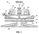
- a print creation apparatus 91 (Figs 1 and 2) including upper and lower platen structures 92 and 94, respectively, is provided for producing simulated photographic prints using xerography.
- the lower platen comprises a rigid metal plate or base member 96 containing a silicone rubber pad 98 having a thickness of approximately 0.5 inch (12 7 mm)
- a flat rigid member supported on the silicone rubber pad comprises a 3/8 inch (9 5 mm) thick, smooth-surfaced, tempered glass member 100.
- the smooth-surfaced tempered glass serves to smooth any wrinkles created in the transparency material during the imaging process.
- the upper platen 92 contains a heater structure 102 (Fig. 2) including heating elements 104.
- the plate or base member 96 is provided with a leg structure 106 for supporting the the print making structure 91 on a suitable work surface such as a table.
- the upper platen 92 is hingedly secured via hinge structure 108 to an upper platen support structure 110.
- the support structure 110 is, in turn, operatively supported by a post member 112 received in a cylindrically shaped receiver member 114 forming an integral part of the plate or base member 96.
- the support structure is adapted to be pivoted relative to the base member 96 through the use of an arm and knob arrangement 115 attached to the support structure 110.
- the upper heated platen can thus be rotated from its home position overlying the tempered glass member 100 in order to provide easy access thereto for inserting the materials used for print creation.
- the transparency 25 containing the toner images is placed, image side up, on the tempered glass 100 and a colored (i.e. green, blue or yellow, etc.) translucent sheet member 116 comprising a coated paper material is placed in contact with the toner image on the transparent substrate 25.
- a colored (i.e. green, blue or yellow, etc.) translucent sheet member 116 comprising a coated paper material is placed in contact with the toner image on the transparent substrate 25.
- Each side or surface of the sheet 116 is coated with and thereby serves as a carrier for a uniform coating of adhesive material 118 which is applied to a thickness of about 0.00025 inch (6.35 ⁇ m).
- adhesives can be selected for use in the present invention including materials that will enable the layers to substantially permanently bond to each other and not easily separate after extended time periods, such as for up to 1 year.
- suitable adhesives include polyesters, such as those available from Goodyear Chemical and E.I. Du Pont, polyvinylacetate, phenolics, epoxy resins, certain polyacrylates polycyanoacrylates, cellulosic esters. These adhesives are selected in various effective amounts such as for example from about 1 to about 75 weight percent and preferably from about 0.1 to about 25 weight percent.
- the adhesive layer thickness is generally from about 0.1 ⁇ m to about 25 ⁇ m, and preferably from about 1 to about 10 ⁇ m or more in embodiments, however other effective thickness may be selected.
- An aerosol or spray adhesive has been used with satisfactory results. Specifically, a commercially available adhesive sold by the 3M Co. under the name of SUPER 77 has been used. The aforementioned adhesive is provided in a spray can dispenser and, therefore, it can be easily applied to the sheet 116.
- SUPER 77 spray adhesive is a high tack, high coverage material and a fast drying composition that is heat activated at about 225°F. (107°C).
- This bonding film comprises 40 to 50 % by weight of polyterpene resin, 30 to 40 % by weight of ethylene-vinyl acetate polymer, 10 to 20 % by weight of polyethylene and 1 to 10 % by weight of thermoplastic polymer.
- a layer of this bonding film may be applied directly to the sheets 116 or it may be transferred thereto using a carrier sheet containing the bonding film as provided by the manufacturer. In the case of the latter method, the sheet 116 and the film carrier are simultaneously heated while contacting each other for effecting transfer of the bonding film to the backing sheet 116.
- a clear or nonimaged transparent substrate 124 is placed on top of the adhesive layer 122 on the top of the sheet 116 for bonding to that side of the sheet 116 By bonding the substrate 124 to the backside of the sheet 116, it is provided with substrates having identical properties as those of the transparent substrate 25 on both sides of the sheet to improve the flatness of a finished print compared to the situation where only the imaged transparent substrate is used in the final print.
- the member 120 comprises a sheet or film of polyester or Mylar, commercially available from E.I. DuPont which sheet has at least one of its sides coated with an abhesive layer 122 of silicone rubber. For sake of convenient use, both sides of the member 120 can be provided with a layer 122. Thus, with both sides of the polyester film coated with silicone rubber, either side thereof can contact the sheet member 116.
- the film has a thickness of approximately 0 004 inch (102 ⁇ m) while each silicone layer has a thickness of approximately 5 to 10 ⁇ m.
- a suitable coated paper 116 is disclosed in US-A-5,075,153.
- the coated paper comprises a plastic supporting substrate such as polyester rather than natural cellulose, with certain coatings thereover.
- Mylar commercially available from E.I. DuPont is preferred as the substrate for the coated sheet 116 in view of its availability and lower cost.
- the coated sheet 116 has a thickness of about 0.004 inch (102 ⁇ m).
- the hinge mechanism 108 is located centrally of the upper platen 92 and serves to allow movement of the upper platen 92 relative to the support structure 110, such movement being toward the lower platen 94 for exerting pressure on the print forming members supported on the tempered glass member 100. Movement of the upper platen is effected through the use of a lever arm 126 adapted to be moved in the counterclockwise direction as viewed in Fig. 1.
- Pressure variation or adjustment is effected through a pressure adjusting knob 128 and suitable linkage, not shown.
- the adjustment of the knob through its associated linkage mechanism serves to control the amount of pressure exerted between the upper and lower platens when the lever lever arm 126 is actuated.
- An electric cord (not shown) provides electrical current to the heating elements 104.
- the heating elements and thus the operating temperature of the print creation structure 91 is controlled via a temperature control 132 carried by the support structure 110 as shown in Fig. 1.
- the operating temperature of the device is in the range of 220 to 250 °F. (105 - 120°C).
- the pressure and heat are applied for between 15 to 20 seconds, the time being settable via a timer control knob 134.
- the transparent substrate and coated paper members are subjected to a total pressure in the order of 5 to 10 pounds over the entire area of 8.5 x11 (21.6x27 9 cm) and 11x17 inch (27.9x43.2 cm) print forming members. Since the translucent backing of the print is colored, the finished print exhibits that color. As will be appreciated since the final print comprises the translucent backing member and the transparent front member, the print may be illuminated from the rear with very pleasing results.
- the resulting simulated photographic print has a total thickness of approximately 0.009 inch (229 ⁇ m).
- a print 136 created according to the present invention has a thickness approximately equal to a conventional photograph which is approximately 0.009 inch (229 ⁇ m).
- the transparent substrate 25 without toner images thereon, coated paper 116, tempered glass 100 and abhesive or non-stick member 120 form a kit which can be used for creating simulated photographic prints.
- the transparent substrate 25 may be used in a machine like the 5775TM or any other suitable xerographic processor for forming either a black and white or color reverse reading image thereon.
- a commercially available heat and pressure device can then be used to adhere a sheet of coated paper to the image side of the transparent substrate.
- a heat and pressure device contemplated for making simulated photographic prints using the aforementioned kit is currently used for applying decals (decal applicator) onto shirts and other articles of clothing.
- the transparent substrate 25 and coated sheet 116 are placed on top of the tempered glass.
- the abhesive member is placed on top of the coated sheet. Heat and pressure are then applied in a manner consistent with the normal operation of the decal applicator.
Landscapes
- Physics & Mathematics (AREA)
- General Physics & Mathematics (AREA)
- Fixing For Electrophotography (AREA)
- Combination Of More Than One Step In Electrophotography (AREA)
- Optical Systems Of Projection Type Copiers (AREA)
- Color Electrophotography (AREA)
Applications Claiming Priority (2)
| Application Number | Priority Date | Filing Date | Title |
|---|---|---|---|
| US95643 | 1987-09-14 | ||
| US08/095,643 US5357326A (en) | 1993-07-21 | 1993-07-21 | High quality color highlight prints using B/W xerography |
Publications (3)
| Publication Number | Publication Date |
|---|---|
| EP0635765A2 EP0635765A2 (en) | 1995-01-25 |
| EP0635765A3 EP0635765A3 (OSRAM) | 1995-02-15 |
| EP0635765B1 true EP0635765B1 (en) | 2000-04-26 |
Family
ID=22252938
Family Applications (1)
| Application Number | Title | Priority Date | Filing Date |
|---|---|---|---|
| EP94305290A Expired - Lifetime EP0635765B1 (en) | 1993-07-21 | 1994-07-19 | High quality highlight colour prints using B/W electrography |
Country Status (4)
| Country | Link |
|---|---|
| US (1) | US5357326A (OSRAM) |
| EP (1) | EP0635765B1 (OSRAM) |
| JP (1) | JPH0756412A (OSRAM) |
| DE (1) | DE69424097T2 (OSRAM) |
Families Citing this family (5)
| Publication number | Priority date | Publication date | Assignee | Title |
|---|---|---|---|---|
| GB2300384A (en) * | 1995-05-04 | 1996-11-06 | Xeikon Nv | Method and apparatus for forming laminated articles |
| JP3897863B2 (ja) * | 1997-08-19 | 2007-03-28 | 富士ゼロックス株式会社 | 画像形成方法 |
| US5887234A (en) * | 1997-12-17 | 1999-03-23 | Eastman Kodak Company | Reproduction apparatus providing selectable image quality and gloss |
| US6260509B1 (en) | 1998-11-24 | 2001-07-17 | Eastman Kodak Company | Textured photographic prints resistant to handling hazards |
| JP2007196553A (ja) * | 2006-01-27 | 2007-08-09 | Konica Minolta Business Technologies Inc | キャリブレーション方法、画像形成システム、画像形成装置及びキャリブレーションプログラム |
Family Cites Families (15)
| Publication number | Priority date | Publication date | Assignee | Title |
|---|---|---|---|---|
| JPS4926904B1 (OSRAM) * | 1970-12-29 | 1974-07-12 | ||
| US3914097A (en) * | 1974-02-01 | 1975-10-21 | Eastman Kodak Co | Sheet guide and cooling apparatus |
| US4066802A (en) * | 1975-12-22 | 1978-01-03 | Xerox Corporation | Colored xerographic image transfer process |
| US4178096A (en) * | 1978-04-10 | 1979-12-11 | John F. Lontz Associates, Inc. | High fidelity color prints |
| US4470861A (en) * | 1980-03-21 | 1984-09-11 | The Vollrath Company | Decorated laminate having indicia applied photoelectrographically and method of making same |
| US4510225A (en) * | 1982-09-24 | 1985-04-09 | Coulter Systems Corporation | Electrophotographic method for producing an opaque print |
| JPS60234873A (ja) * | 1984-05-08 | 1985-11-21 | Fuji Xerox Co Ltd | フイルム融着機能付き電子複写機 |
| US4600669A (en) * | 1984-12-26 | 1986-07-15 | Eastman Kodak Company | Electrophotographic color proofing element and method for using the same |
| US4686163A (en) * | 1984-12-26 | 1987-08-11 | Eastman Kodak Company | Electrophotographic color imaging method |
| US4724026A (en) * | 1985-02-05 | 1988-02-09 | Omnicrom Systems Corporation | Process for selective transfer of metallic foils to xerographic images |
| US4868049A (en) * | 1985-02-05 | 1989-09-19 | Omnicrom Systems Limited | Selective metallic transfer foils for xerographic images |
| AU2523188A (en) * | 1987-10-02 | 1989-04-18 | Toyo Seikan Kaisha Ltd. | Multi-color printing method for container |
| US4949103A (en) * | 1989-08-28 | 1990-08-14 | Xerox Corporation | Direct electrostatic printing apparatus and method for making labels |
| US5126797A (en) * | 1989-11-13 | 1992-06-30 | Eastman Kodak Company | Method and apparatus for laminating toner images on receiving sheets |
| US5108865A (en) * | 1990-04-18 | 1992-04-28 | Minnesota Mining And Manufacturing Company | Offset transfer of toner images in electrography |
-
1993
- 1993-07-21 US US08/095,643 patent/US5357326A/en not_active Expired - Fee Related
-
1994
- 1994-07-13 JP JP6160910A patent/JPH0756412A/ja active Pending
- 1994-07-19 EP EP94305290A patent/EP0635765B1/en not_active Expired - Lifetime
- 1994-07-19 DE DE69424097T patent/DE69424097T2/de not_active Expired - Fee Related
Also Published As
| Publication number | Publication date |
|---|---|
| EP0635765A2 (en) | 1995-01-25 |
| EP0635765A3 (OSRAM) | 1995-02-15 |
| DE69424097D1 (de) | 2000-05-31 |
| DE69424097T2 (de) | 2000-10-05 |
| JPH0756412A (ja) | 1995-03-03 |
| US5357326A (en) | 1994-10-18 |
Similar Documents
| Publication | Publication Date | Title |
|---|---|---|
| EP0635761B1 (en) | Method of forming simulated photographic prints | |
| US5327201A (en) | Simulated photographic prints using a reflective coating | |
| US5983064A (en) | Auxiliary processor for making simulated photographic prints | |
| EP0443008B1 (en) | Toner fixing method | |
| EP0678789B1 (en) | Production of a simulated glossy coating | |
| EP0443014B1 (en) | Methods and apparatus for texturizing toner image bearing receiving sheets and product produced thereby | |
| US5249949A (en) | Apparatus for texturizing toner image bearing receiving sheets | |
| JPH0350586A (ja) | 電子写真式複写画像及び複写方法 | |
| JPH0756409A (ja) | 擬似写真プリント作成方法 | |
| EP0635765B1 (en) | High quality highlight colour prints using B/W electrography | |
| US5112717A (en) | Method and apparatus for treating toner image bearing receiving sheets | |
| EP0635763A2 (en) | A simulated, photographic print making kit | |
| EP0644464B1 (en) | Simulated photographic prints using xerography | |
| JP2788358B2 (ja) | 電子写真用被転写フィルムおよびカラー画像形成方法 | |
| JPH07168415A (ja) | 疑似写真プリントを作成する方法 | |
| JP4225143B2 (ja) | 情報記録媒体、その製造方法、及び、該製造方法に用いる情報記録媒体製造装置 | |
| JP2866762B2 (ja) | 電子写真用被転写フィルム | |
| JP2001083834A (ja) | 画像形成方法および画像形成方法で使用する定着装置 | |
| JPH09160278A (ja) | 電子写真用光透過性被記録材及びこれを用いた加熱定着方法 | |
| JPH10133409A (ja) | 電子写真用光透過性被記録材及びこれを用いた加熱定着方法 | |
| JPH05273877A (ja) | 画像形成装置 | |
| JP2002139872A (ja) | 画像形成方法、画像形成装置及び画像形成用透明フィルム | |
| JP2002148843A (ja) | 画像形成方法、画像形成装置及び透明フィルム |
Legal Events
| Date | Code | Title | Description |
|---|---|---|---|
| PUAI | Public reference made under article 153(3) epc to a published international application that has entered the european phase |
Free format text: ORIGINAL CODE: 0009012 |
|
| PUAL | Search report despatched |
Free format text: ORIGINAL CODE: 0009013 |
|
| AK | Designated contracting states |
Kind code of ref document: A2 Designated state(s): DE FR GB |
|
| AK | Designated contracting states |
Kind code of ref document: A3 Designated state(s): DE FR GB |
|
| 17P | Request for examination filed |
Effective date: 19950816 |
|
| 17Q | First examination report despatched |
Effective date: 19961217 |
|
| GRAG | Despatch of communication of intention to grant |
Free format text: ORIGINAL CODE: EPIDOS AGRA |
|
| GRAG | Despatch of communication of intention to grant |
Free format text: ORIGINAL CODE: EPIDOS AGRA |
|
| GRAH | Despatch of communication of intention to grant a patent |
Free format text: ORIGINAL CODE: EPIDOS IGRA |
|
| GRAH | Despatch of communication of intention to grant a patent |
Free format text: ORIGINAL CODE: EPIDOS IGRA |
|
| GRAA | (expected) grant |
Free format text: ORIGINAL CODE: 0009210 |
|
| AK | Designated contracting states |
Kind code of ref document: B1 Designated state(s): DE FR GB |
|
| REF | Corresponds to: |
Ref document number: 69424097 Country of ref document: DE Date of ref document: 20000531 |
|
| ET | Fr: translation filed | ||
| PLBE | No opposition filed within time limit |
Free format text: ORIGINAL CODE: 0009261 |
|
| STAA | Information on the status of an ep patent application or granted ep patent |
Free format text: STATUS: NO OPPOSITION FILED WITHIN TIME LIMIT |
|
| 26N | No opposition filed | ||
| REG | Reference to a national code |
Ref country code: GB Ref legal event code: IF02 |
|
| PGFP | Annual fee paid to national office [announced via postgrant information from national office to epo] |
Ref country code: FR Payment date: 20020709 Year of fee payment: 9 |
|
| PGFP | Annual fee paid to national office [announced via postgrant information from national office to epo] |
Ref country code: GB Payment date: 20020717 Year of fee payment: 9 |
|
| PGFP | Annual fee paid to national office [announced via postgrant information from national office to epo] |
Ref country code: DE Payment date: 20020724 Year of fee payment: 9 |
|
| PG25 | Lapsed in a contracting state [announced via postgrant information from national office to epo] |
Ref country code: GB Free format text: LAPSE BECAUSE OF NON-PAYMENT OF DUE FEES Effective date: 20030719 |
|
| PG25 | Lapsed in a contracting state [announced via postgrant information from national office to epo] |
Ref country code: DE Free format text: LAPSE BECAUSE OF NON-PAYMENT OF DUE FEES Effective date: 20040203 |
|
| GBPC | Gb: european patent ceased through non-payment of renewal fee |
Effective date: 20030719 |
|
| PG25 | Lapsed in a contracting state [announced via postgrant information from national office to epo] |
Ref country code: FR Free format text: LAPSE BECAUSE OF NON-PAYMENT OF DUE FEES Effective date: 20040331 |
|
| REG | Reference to a national code |
Ref country code: FR Ref legal event code: ST |