EP0634980B1 - ANTRIEBSSTRANG MIT VORRICHTUNG ZUR ERFASSUNG UND KORREKTUR DES RèCKROLLZUSTANDES EINES ELEKTRISCHEN FAHRZEUGS - Google Patents
ANTRIEBSSTRANG MIT VORRICHTUNG ZUR ERFASSUNG UND KORREKTUR DES RèCKROLLZUSTANDES EINES ELEKTRISCHEN FAHRZEUGS Download PDFInfo
- Publication number
- EP0634980B1 EP0634980B1 EP94908003A EP94908003A EP0634980B1 EP 0634980 B1 EP0634980 B1 EP 0634980B1 EP 94908003 A EP94908003 A EP 94908003A EP 94908003 A EP94908003 A EP 94908003A EP 0634980 B1 EP0634980 B1 EP 0634980B1
- Authority
- EP
- European Patent Office
- Prior art keywords
- electric motor
- vehicle
- rollback
- controlling
- drive train
- Prior art date
- Legal status (The legal status is an assumption and is not a legal conclusion. Google has not performed a legal analysis and makes no representation as to the accuracy of the status listed.)
- Expired - Lifetime
Links
- 238000001514 detection method Methods 0.000 title claims description 23
- 238000012886 linear function Methods 0.000 claims abstract description 10
- 230000001133 acceleration Effects 0.000 claims description 11
- 238000000034 method Methods 0.000 claims description 11
- 230000004044 response Effects 0.000 claims description 3
- 230000005540 biological transmission Effects 0.000 description 12
- 238000005096 rolling process Methods 0.000 description 5
- 230000006698 induction Effects 0.000 description 3
- 230000003278 mimic effect Effects 0.000 description 3
- 230000008901 benefit Effects 0.000 description 2
- 230000033228 biological regulation Effects 0.000 description 2
- 230000008878 coupling Effects 0.000 description 2
- 238000010168 coupling process Methods 0.000 description 2
- 238000005859 coupling reaction Methods 0.000 description 2
- 230000000994 depressogenic effect Effects 0.000 description 2
- 238000010586 diagram Methods 0.000 description 2
- 239000012530 fluid Substances 0.000 description 2
- 230000004048 modification Effects 0.000 description 2
- 238000012986 modification Methods 0.000 description 2
- 230000007704 transition Effects 0.000 description 2
- 208000012661 Dyskinesia Diseases 0.000 description 1
- 238000004378 air conditioning Methods 0.000 description 1
- 230000003466 anti-cipated effect Effects 0.000 description 1
- 239000003245 coal Substances 0.000 description 1
- 238000002485 combustion reaction Methods 0.000 description 1
- 238000010276 construction Methods 0.000 description 1
- 230000000881 depressing effect Effects 0.000 description 1
- 238000005516 engineering process Methods 0.000 description 1
- 230000005484 gravity Effects 0.000 description 1
- 230000007935 neutral effect Effects 0.000 description 1
- 230000001681 protective effect Effects 0.000 description 1
- 238000011084 recovery Methods 0.000 description 1
- 230000009467 reduction Effects 0.000 description 1
- 230000001172 regenerating effect Effects 0.000 description 1
- 238000005303 weighing Methods 0.000 description 1
Images


Classifications
-
- B—PERFORMING OPERATIONS; TRANSPORTING
- B60—VEHICLES IN GENERAL
- B60L—PROPULSION OF ELECTRICALLY-PROPELLED VEHICLES; SUPPLYING ELECTRIC POWER FOR AUXILIARY EQUIPMENT OF ELECTRICALLY-PROPELLED VEHICLES; ELECTRODYNAMIC BRAKE SYSTEMS FOR VEHICLES IN GENERAL; MAGNETIC SUSPENSION OR LEVITATION FOR VEHICLES; MONITORING OPERATING VARIABLES OF ELECTRICALLY-PROPELLED VEHICLES; ELECTRIC SAFETY DEVICES FOR ELECTRICALLY-PROPELLED VEHICLES
- B60L15/00—Methods, circuits, or devices for controlling the traction-motor speed of electrically-propelled vehicles
- B60L15/20—Methods, circuits, or devices for controlling the traction-motor speed of electrically-propelled vehicles for control of the vehicle or its driving motor to achieve a desired performance, e.g. speed, torque, programmed variation of speed
- B60L15/2009—Methods, circuits, or devices for controlling the traction-motor speed of electrically-propelled vehicles for control of the vehicle or its driving motor to achieve a desired performance, e.g. speed, torque, programmed variation of speed for braking
- B60L15/2018—Methods, circuits, or devices for controlling the traction-motor speed of electrically-propelled vehicles for control of the vehicle or its driving motor to achieve a desired performance, e.g. speed, torque, programmed variation of speed for braking for braking on a slope
-
- B—PERFORMING OPERATIONS; TRANSPORTING
- B60—VEHICLES IN GENERAL
- B60L—PROPULSION OF ELECTRICALLY-PROPELLED VEHICLES; SUPPLYING ELECTRIC POWER FOR AUXILIARY EQUIPMENT OF ELECTRICALLY-PROPELLED VEHICLES; ELECTRODYNAMIC BRAKE SYSTEMS FOR VEHICLES IN GENERAL; MAGNETIC SUSPENSION OR LEVITATION FOR VEHICLES; MONITORING OPERATING VARIABLES OF ELECTRICALLY-PROPELLED VEHICLES; ELECTRIC SAFETY DEVICES FOR ELECTRICALLY-PROPELLED VEHICLES
- B60L15/00—Methods, circuits, or devices for controlling the traction-motor speed of electrically-propelled vehicles
- B60L15/20—Methods, circuits, or devices for controlling the traction-motor speed of electrically-propelled vehicles for control of the vehicle or its driving motor to achieve a desired performance, e.g. speed, torque, programmed variation of speed
- B60L15/2009—Methods, circuits, or devices for controlling the traction-motor speed of electrically-propelled vehicles for control of the vehicle or its driving motor to achieve a desired performance, e.g. speed, torque, programmed variation of speed for braking
-
- B—PERFORMING OPERATIONS; TRANSPORTING
- B60—VEHICLES IN GENERAL
- B60L—PROPULSION OF ELECTRICALLY-PROPELLED VEHICLES; SUPPLYING ELECTRIC POWER FOR AUXILIARY EQUIPMENT OF ELECTRICALLY-PROPELLED VEHICLES; ELECTRODYNAMIC BRAKE SYSTEMS FOR VEHICLES IN GENERAL; MAGNETIC SUSPENSION OR LEVITATION FOR VEHICLES; MONITORING OPERATING VARIABLES OF ELECTRICALLY-PROPELLED VEHICLES; ELECTRIC SAFETY DEVICES FOR ELECTRICALLY-PROPELLED VEHICLES
- B60L50/00—Electric propulsion with power supplied within the vehicle
- B60L50/10—Electric propulsion with power supplied within the vehicle using propulsion power supplied by engine-driven generators, e.g. generators driven by combustion engines
- B60L50/16—Electric propulsion with power supplied within the vehicle using propulsion power supplied by engine-driven generators, e.g. generators driven by combustion engines with provision for separate direct mechanical propulsion
-
- B—PERFORMING OPERATIONS; TRANSPORTING
- B60—VEHICLES IN GENERAL
- B60L—PROPULSION OF ELECTRICALLY-PROPELLED VEHICLES; SUPPLYING ELECTRIC POWER FOR AUXILIARY EQUIPMENT OF ELECTRICALLY-PROPELLED VEHICLES; ELECTRODYNAMIC BRAKE SYSTEMS FOR VEHICLES IN GENERAL; MAGNETIC SUSPENSION OR LEVITATION FOR VEHICLES; MONITORING OPERATING VARIABLES OF ELECTRICALLY-PROPELLED VEHICLES; ELECTRIC SAFETY DEVICES FOR ELECTRICALLY-PROPELLED VEHICLES
- B60L50/00—Electric propulsion with power supplied within the vehicle
- B60L50/50—Electric propulsion with power supplied within the vehicle using propulsion power supplied by batteries or fuel cells
- B60L50/60—Electric propulsion with power supplied within the vehicle using propulsion power supplied by batteries or fuel cells using power supplied by batteries
- B60L50/66—Arrangements of batteries
-
- B—PERFORMING OPERATIONS; TRANSPORTING
- B60—VEHICLES IN GENERAL
- B60L—PROPULSION OF ELECTRICALLY-PROPELLED VEHICLES; SUPPLYING ELECTRIC POWER FOR AUXILIARY EQUIPMENT OF ELECTRICALLY-PROPELLED VEHICLES; ELECTRODYNAMIC BRAKE SYSTEMS FOR VEHICLES IN GENERAL; MAGNETIC SUSPENSION OR LEVITATION FOR VEHICLES; MONITORING OPERATING VARIABLES OF ELECTRICALLY-PROPELLED VEHICLES; ELECTRIC SAFETY DEVICES FOR ELECTRICALLY-PROPELLED VEHICLES
- B60L2240/00—Control parameters of input or output; Target parameters
- B60L2240/10—Vehicle control parameters
- B60L2240/12—Speed
-
- B—PERFORMING OPERATIONS; TRANSPORTING
- B60—VEHICLES IN GENERAL
- B60L—PROPULSION OF ELECTRICALLY-PROPELLED VEHICLES; SUPPLYING ELECTRIC POWER FOR AUXILIARY EQUIPMENT OF ELECTRICALLY-PROPELLED VEHICLES; ELECTRODYNAMIC BRAKE SYSTEMS FOR VEHICLES IN GENERAL; MAGNETIC SUSPENSION OR LEVITATION FOR VEHICLES; MONITORING OPERATING VARIABLES OF ELECTRICALLY-PROPELLED VEHICLES; ELECTRIC SAFETY DEVICES FOR ELECTRICALLY-PROPELLED VEHICLES
- B60L2240/00—Control parameters of input or output; Target parameters
- B60L2240/40—Drive Train control parameters
- B60L2240/42—Drive Train control parameters related to electric machines
- B60L2240/421—Speed
-
- B—PERFORMING OPERATIONS; TRANSPORTING
- B60—VEHICLES IN GENERAL
- B60L—PROPULSION OF ELECTRICALLY-PROPELLED VEHICLES; SUPPLYING ELECTRIC POWER FOR AUXILIARY EQUIPMENT OF ELECTRICALLY-PROPELLED VEHICLES; ELECTRODYNAMIC BRAKE SYSTEMS FOR VEHICLES IN GENERAL; MAGNETIC SUSPENSION OR LEVITATION FOR VEHICLES; MONITORING OPERATING VARIABLES OF ELECTRICALLY-PROPELLED VEHICLES; ELECTRIC SAFETY DEVICES FOR ELECTRICALLY-PROPELLED VEHICLES
- B60L2240/00—Control parameters of input or output; Target parameters
- B60L2240/40—Drive Train control parameters
- B60L2240/42—Drive Train control parameters related to electric machines
- B60L2240/423—Torque
-
- B—PERFORMING OPERATIONS; TRANSPORTING
- B60—VEHICLES IN GENERAL
- B60L—PROPULSION OF ELECTRICALLY-PROPELLED VEHICLES; SUPPLYING ELECTRIC POWER FOR AUXILIARY EQUIPMENT OF ELECTRICALLY-PROPELLED VEHICLES; ELECTRODYNAMIC BRAKE SYSTEMS FOR VEHICLES IN GENERAL; MAGNETIC SUSPENSION OR LEVITATION FOR VEHICLES; MONITORING OPERATING VARIABLES OF ELECTRICALLY-PROPELLED VEHICLES; ELECTRIC SAFETY DEVICES FOR ELECTRICALLY-PROPELLED VEHICLES
- B60L2240/00—Control parameters of input or output; Target parameters
- B60L2240/40—Drive Train control parameters
- B60L2240/48—Drive Train control parameters related to transmissions
- B60L2240/486—Operating parameters
-
- B—PERFORMING OPERATIONS; TRANSPORTING
- B60—VEHICLES IN GENERAL
- B60L—PROPULSION OF ELECTRICALLY-PROPELLED VEHICLES; SUPPLYING ELECTRIC POWER FOR AUXILIARY EQUIPMENT OF ELECTRICALLY-PROPELLED VEHICLES; ELECTRODYNAMIC BRAKE SYSTEMS FOR VEHICLES IN GENERAL; MAGNETIC SUSPENSION OR LEVITATION FOR VEHICLES; MONITORING OPERATING VARIABLES OF ELECTRICALLY-PROPELLED VEHICLES; ELECTRIC SAFETY DEVICES FOR ELECTRICALLY-PROPELLED VEHICLES
- B60L2250/00—Driver interactions
- B60L2250/26—Driver interactions by pedal actuation
-
- B—PERFORMING OPERATIONS; TRANSPORTING
- B60—VEHICLES IN GENERAL
- B60W—CONJOINT CONTROL OF VEHICLE SUB-UNITS OF DIFFERENT TYPE OR DIFFERENT FUNCTION; CONTROL SYSTEMS SPECIALLY ADAPTED FOR HYBRID VEHICLES; ROAD VEHICLE DRIVE CONTROL SYSTEMS FOR PURPOSES NOT RELATED TO THE CONTROL OF A PARTICULAR SUB-UNIT
- B60W30/00—Purposes of road vehicle drive control systems not related to the control of a particular sub-unit, e.g. of systems using conjoint control of vehicle sub-units
- B60W30/18—Propelling the vehicle
- B60W30/18009—Propelling the vehicle related to particular drive situations
- B60W30/18109—Braking
- B60W30/18118—Hill holding
-
- Y—GENERAL TAGGING OF NEW TECHNOLOGICAL DEVELOPMENTS; GENERAL TAGGING OF CROSS-SECTIONAL TECHNOLOGIES SPANNING OVER SEVERAL SECTIONS OF THE IPC; TECHNICAL SUBJECTS COVERED BY FORMER USPC CROSS-REFERENCE ART COLLECTIONS [XRACs] AND DIGESTS
- Y02—TECHNOLOGIES OR APPLICATIONS FOR MITIGATION OR ADAPTATION AGAINST CLIMATE CHANGE
- Y02T—CLIMATE CHANGE MITIGATION TECHNOLOGIES RELATED TO TRANSPORTATION
- Y02T10/00—Road transport of goods or passengers
- Y02T10/60—Other road transportation technologies with climate change mitigation effect
- Y02T10/64—Electric machine technologies in electromobility
-
- Y—GENERAL TAGGING OF NEW TECHNOLOGICAL DEVELOPMENTS; GENERAL TAGGING OF CROSS-SECTIONAL TECHNOLOGIES SPANNING OVER SEVERAL SECTIONS OF THE IPC; TECHNICAL SUBJECTS COVERED BY FORMER USPC CROSS-REFERENCE ART COLLECTIONS [XRACs] AND DIGESTS
- Y02—TECHNOLOGIES OR APPLICATIONS FOR MITIGATION OR ADAPTATION AGAINST CLIMATE CHANGE
- Y02T—CLIMATE CHANGE MITIGATION TECHNOLOGIES RELATED TO TRANSPORTATION
- Y02T10/00—Road transport of goods or passengers
- Y02T10/60—Other road transportation technologies with climate change mitigation effect
- Y02T10/70—Energy storage systems for electromobility, e.g. batteries
-
- Y—GENERAL TAGGING OF NEW TECHNOLOGICAL DEVELOPMENTS; GENERAL TAGGING OF CROSS-SECTIONAL TECHNOLOGIES SPANNING OVER SEVERAL SECTIONS OF THE IPC; TECHNICAL SUBJECTS COVERED BY FORMER USPC CROSS-REFERENCE ART COLLECTIONS [XRACs] AND DIGESTS
- Y02—TECHNOLOGIES OR APPLICATIONS FOR MITIGATION OR ADAPTATION AGAINST CLIMATE CHANGE
- Y02T—CLIMATE CHANGE MITIGATION TECHNOLOGIES RELATED TO TRANSPORTATION
- Y02T10/00—Road transport of goods or passengers
- Y02T10/60—Other road transportation technologies with climate change mitigation effect
- Y02T10/7072—Electromobility specific charging systems or methods for batteries, ultracapacitors, supercapacitors or double-layer capacitors
-
- Y—GENERAL TAGGING OF NEW TECHNOLOGICAL DEVELOPMENTS; GENERAL TAGGING OF CROSS-SECTIONAL TECHNOLOGIES SPANNING OVER SEVERAL SECTIONS OF THE IPC; TECHNICAL SUBJECTS COVERED BY FORMER USPC CROSS-REFERENCE ART COLLECTIONS [XRACs] AND DIGESTS
- Y02—TECHNOLOGIES OR APPLICATIONS FOR MITIGATION OR ADAPTATION AGAINST CLIMATE CHANGE
- Y02T—CLIMATE CHANGE MITIGATION TECHNOLOGIES RELATED TO TRANSPORTATION
- Y02T10/00—Road transport of goods or passengers
- Y02T10/60—Other road transportation technologies with climate change mitigation effect
- Y02T10/72—Electric energy management in electromobility
Definitions
- the present invention relates to the field of electric vehicles, and more particularly, to a drive train for an electric vehicle including control of electric motor torque output.
- Electric vehicles are receiving considerable attention as a substitute for present gasoline-fueled vehicles. This interest is based primarily on zero atmospheric emissions obtainable from an all-electric vehicle. Several states are considering stricter emissions regulations for vehicles, and California has adopted regulations that will require zero emissions for a percentage of vehicles in certain urban areas. Electric vehicles also offer other advantages including reducing dependency on imported oil, since utilities in the United States generate a large portion of their energy demands using coal, gas, nuclear, and hydroelectric sources.
- hybrid electric vehicles such as those incorporating a small gasoline engine running at a constant speed to recharge an electric traction battery, offer anticipated lower emissions.
- U.S. Patent No. 4,351,405 to Fields et al. which discloses a hybrid vehicle including a gasoline engine for driving the front wheels during high speed and long distance driving, while the rear wheels are connected to electric motors for low speed and stop and go driving.
- an electric vehicle should desirably mimic the operation of such a conventional gasoline vehicle, especially the drive train including a conventional automatic transmission.
- Functions such as braking and acceleration are readily controlled in an electric vehicle through a conventional brake pedal and accelerator pedal.
- the selection of drive, reverse, park, and neutral positions are also imitated on an electric vehicle.
- the engine always rotates in a same direction and the vehicle includes a clutch or fluid coupling to transmit torque to the vehicle wheels.
- a conventional automatic transmission will tend to start the vehicle moving forward, or creep, on a level surface once the driver releases the brake with the engine idling.
- starts upward on an incline are readily accommodated in a gasoline vehicle because the creep of the automatic transmission compensates for vehicle rollback during the time from when the driver releases the brake until the driver can depress the accelerator.
- a conventional vehicle with a standard transmission includes numerous contributors of rolling friction which have a tendency to reduce the speed of rollback when starting upward on an incline.
- An electric vehicle may have one or more electric motors directly driving the wheels as disclosed in U.S. Patent No. 4,913,258 to Sakuri et al.
- an electric vehicle may have an electric motor driving a set of wheels through a gearbox and differential. Since the electric motor does not typically "idle" as a conventional gasoline engine, a typical electric vehicle has a tendency to first roll backwards when starting upward on an incline. This rollback is particularly troublesome in traffic where the vehicle may roll backwards into the vehicle behind.
- the motor is rotating in a direction opposite to the desired direction of travel, and gear lash and drive shaft spring must first be taken up from the drive train before the vehicle may begin to move forward.
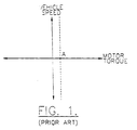
- Battery powered vehicles such as automobiles, forklifts, and other utility vehicles, typically include some form of motor control logic that may assist in starting the vehicle when the vehicle is positioned on a grade. Creep, as in a gasoline vehicle, has been simulated in an electric forklift for operation on a level surface as shown in the graph of vehicle speed versus motor torque of FIG. 1, wherein a forward direction of intended movement is selected.
- the forklift control computer applies power to the motor to generate a predetermined constant output torque indicated by Point A on the graph, irrespective of the vehicle speed.
- WO/84/02813 discloses a vehicle powered by an electric motor including a motor control apparatus for producing a type of electrical braking known as a plugging and for automatically overriding the electrical braking in response to predetermined conditions.
- the motor is operated by a predetermined pulse train if a plugging condition exists. If the plugging override feature is activated (by depressing the accelerator) during vehicle roll back, the predetermined pulse train is replaced by a modified pulse train.
- DE-A-2,411,550 describes a system for starting an electrically powered vehicle on a slope without any rollback, using an accelerometer.
- the timed ramp function is undesirable for starting on a grade.
- the timed ramp is set to a relatively slow initial setting so that torque does not build up too quickly; however, with this same setting, substantial rollback may still occur on a grade because of the slowness of increasing torque.
- a drive train (20) for an electric vehicle comprising:
- the drive train preferably counteracts "backward” rollback when the forward or "D” direction is selected and the vehicle is facing upward on an incline. Similarly, the drive train counteracts "forward” rollback when the "R” direction is selected and the vehicle is facing backwards up an incline.
- the drive train may also advantageously provide a smooth transition when the vehicle is accidentally or inadvertently shifted into reverse, for example, while moving in a forward direction.
- the present invention also takes up gear lash and any spring in the drive shaft(s) to thereby provide smoother starting.
- the sensing means associated with the motor preferably includes means for sensing a rotational speed of the motor which corresponds to the speed of the vehicle, since the motor is typically coupled to the vehicle wheels through a gear reduction transmission.
- the rollback detection and compensation means includes means for controlling the output torque magnitude of the electric motor as a nonconstant function of rotational speed of the motor during vehicle rollback.
- the output torque magnitude is controlled as a linear function of rotational speed of the electric motor.
- the output torque magnitude is controlled as a function of the square of the sensed rotational speed of the motor.
- Other nonconstant functions of torque control based upon speed are also contemplated by the present invention.
- the output torque magnitude of the electric motor is also preferably set at a predetermined constant value responsive to a rotational speed of the electric motor being above a predetermined value.
- the electric motor is preferably an induction motor utilizing a form of vector control, such as achieved using a universal field orientation controller, while those skilled in the art will recognize that other types of electric motor drives having a controllable output torque magnitude may also be used.
- the drive train according to the invention also preferably includes a traction battery carried by the vehicle frame. The traction battery is also connected to the induction motor, such as through a suitable power control circuit including a DC-to-AC inverter.
- the drive train preferably also includes driver input means for permitting driver selection of one of vehicle braking or vehicle acceleration.
- the driver input means also preferably includes conventional brake and accelerator pedals.
- Control means is preferably connected to the electric motor for controlling the output torque magnitude and rotational direction thereof in response to the accelerator and brake pedals during normal driving of the vehicle.
- the rollback detection and compensation means cooperates with the control means to counteract vehicle rollback even in an absence of driver selection of one of vehicle braking or acceleration, as when the driver is moving his foot from the brake pedal to the accelerator pedal.
- the drive train of the present invention will closely mimic the operation of a conventional gasoline-fueled vehicle having an automatic transmission, by preventing substantial rollback when starting upward on a hill. Rollback in an electric vehicle may be even more severe than may occur with a conventional vehicle, because rolling resistance is minimized in an electric vehicle to provide greater range for a given battery capacity.
- the rollback detection and compensation means includes means for generating a first torque request value as a function of rotational speed of the electric motor during vehicle rollback.
- the control means further includes means for generating a second torque request value responsive to the driver's selection of acceleration; for example, as when starting upward on an incline.
- the rollback detection and compensation means includes means for adding the first and second torque request values together to control the magnitude of the torque output of the electric motor.
- a method for operating an electric vehicle including an electric motor for driving one or more wheels of the vehicle and being rotatable in opposite directions corresponding to respective opposite directions of actual vehicle movement, and a selector for permitting driver selection of a direction of intended vehicle movement, said method comprising the steps of:
- the vehicle 10 includes a body 11 that may be carried by a separate supporting frame, or the vehicle may be of unibody construction thereby having a body with an integral frame, as would be readily understood by those skilled in the art.
- the vehicle's wheels 12 are rotatably mounted to the frame.
- the drive train according to the present invention may also have applicability to hybrid types of electric vehicles which include an additional power source, such as an internal combustion engine.
- a traction battery 13 is carried by the frame of the vehicle 10 in a lower medial and rearward portion to thus provide a lower center of gravity and more even weight distribution between the front and rear wheels.
- the traction battery 13 preferably comprises a plurality of rechargeable interconnected battery cells.
- the vehicle 10 preferably includes a Vehicle Control Unit (VCU) 14 which, among other tasks, determines and sends a desired torque request signal to a control computer for a DC-to-AC inverter, both of which are enclosed within a protective housing 15 under the hood of the vehicle.
- VCU Vehicle Control Unit
- the desired torque request signal is processed by the control computer for the DC-to-AC inverter to drive the electric motor 16 to the desired torque output magnitude, and in the desired rotational direction corresponding to the intended direction of vehicle movement.
- the electric motor 16 may preferably be an induction motor utilizing some form of vector control. However, those skilled in the art will recognize that other types of electric motor drives having a readily controllable output torque magnitude may also be used.
- the vehicle 10 may also preferably include other related components, such as a twelve volt accessory battery 17 and an electrically-powered air conditioning compressor 18 .
- the drive train 20 is further explained.
- the drive train components are controlled by control means, such as including the controller 21 as illustrated.
- the controller 21 preferably includes one or more microprocessors operating under stored program control.
- the control means may be provided by the VCU 14 and/or the control computer associated with the DC-to-AC inverter (FIG. 2).
- the controller 21 may receive inputs from an "ignition” switch 25 , an accelerator position transducer 26 , a brake position transducer 27 , and a gear selector (PRND) 28 for operating the electric motor 16 for driving and braking the vehicle.
- the gear selector 28 provides selector means for permitting a driver to select an intended or desired direction of vehicle movement, that is, either "D" for forward movement, and "R” for reverse movement.
- the controller 21 delivers power from the traction battery 13 to the electric motor 16 during normal driving.
- the electric motor 16 is rotatable in opposite directions which correspond to respective opposite directions of vehicle movement.
- the controller 21 may also operate the motor 16 in a regenerative braking mode wherein the motor is operated as a generator to slow the vehicle, while simultaneously recharging the traction battery 13 .
- the electric motor 16 is connected to drive one or more of the vehicle wheels 12 directly or through a transmission 22 as shown in the illustrated embodiment.
- a differential may be used to permit a single motor to drive a set of vehicle wheels.
- the electric motor 16 includes an output shaft 16a coupled to an input of the transmission 22 .
- the transmission 22 includes an output shaft 22a coupled to one or more of the vehicle wheels 12 as shown in the illustrated embodiment.
- First and second sensors 23a , 23b are preferably associated with respective shafts of the electric motor 16 and the transmission 22 .
- the sensors 23a , 23b preferably provide both the rotational speed and the direction of rotation for the electric motor 16 and transmission 22 , respectively.
- the controller 21 includes rollback detection and compensation means responsive to the sensing means 23a and selector means 28 for determining vehicle rollback and for operating the electric motor 16 to counteract the vehicle rollback.
- Vehicle rollback is defined by a sensed direction of actual vehicle movement opposite to a selected direction of intended vehicle movement. The sensed direction of vehicle movement corresponds to a respective rotational direction of the electric motor 16 .
- the rollback detection and compensation means counteracts vehicle rollback particularly even in the absence of driver selection of one of vehicle braking or acceleration.
- the drive train 20 of the present invention will closely mimic the operation of an automatic transmission in a conventional gasoline-fueled vehicle, by preventing substantial rollback when starting upward on a hill.
- the rollback detection and compensation means of the drive train 20 preferably counteracts "backward" rollback when the forward or "D" position is selected and the vehicle is facing up an incline.
- the following description is directed to the case of starting upward on an incline in the forward direction.
- Those of skill in the art will readily appreciate the similar case contemplated by the invention for counteracting "forward" rollback when the "R" position is selected and the vehicle is facing backwards up an incline.
- the rollback detection and compensation means in addition to assisting in starting upward on an incline, also advantageously provides a smooth transition when the vehicle is accidentally shifted into reverse, for example, while the vehicle is moving in a forward direction.
- the rollback detection and compensation means may also take up gear lash and any spring in the drive shaft(s) to thereby provide smoother starting on a hill.
- the rollback detection and compensation means includes means for controlling an output torque magnitude of the electric motor 16 as a nonconstant function of rotational speed of the motor during vehicle rollback.
- the output torque magnitude of the electric motor is a linear function of the sensed rotational speed of the electric motor as shown in the graph of FIG. 4.
- the upper right hand quadrant of the graph indicates the case where forward is selected as the intended direction of vehicle movement and the vehicle is moving in the forward direction, such as during normal driving.
- the lower right hand quadrant of the graph represents a rollback condition wherein a "positive" torque is being produced, while the vehicle moves in a backward unintended direction.
- a linear function of torque output versus speed provides the electric motor output torque magnitude to counteract the vehicle rollback.
- the linear function intersects the x-axis for torque at Point B .
- a predetermined value (Point C ) on the y-axis the motor output torque is maintained at a constant level indicated by Point D on the x-axis until the vehicle slows and the torque then follows the linear portion of the curve.
- a torque magnitude of about 149 N.m (110 lbs) is required to hold the vehicle on a 30% grade.
- the 30% grade is the typical maximum grade specification for an automobile.
- the vehicle and grade given if the vehicle is limited to a maximum rollback speed of about 2.4 Km per hour (1.5 mph) (a 100 RPM speed of the motor) the vehicle will be moving backward at a speed of about 0.46 m.sec -1 (1.5 ft/sec).
- a gain constant can be chosen to provide 136 N.m (100 lb ft) and 100 RPM, or 1.36 N.m (one lb ft) per RPM.
- various gain constants can be used to adjust for a wide range of vehicles and other specific rollback speeds.
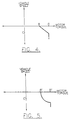
- a torque output function versus a square of the speed may also be implemented if a "stiffer" or quicker recovery from rollback is desired as shown in the graph of FIG. 5. As illustrated in FIG. 5, this function would also preferably include a constant torque above a predetermined speed value as described above.
- the points indicated in prime notation in FIG. 5 are similar to those of FIG. 4.
- Other functions of output torque magnitude versus vehicle speed are also contemplated by the invention.
- the rollback detection and compensation means includes means for generating a first torque request value as a function of rotational speed of the electric motor during vehicle rollback.
- the control means such as the VCU 14 (FIG. 2) also includes means for generating a second torque request value responsive to the driver's selection of acceleration.
- the rollback detection and compensation means preferably includes means for adding the first and second torque request values together to control the magnitude of the torque output of the electric motor.
- a torque request output value is determined as a function of the rollback speed at Block 36 .
- the torque output function may be linear, or based upon the square of the speed, or may be based upon some other nonconstant function of speed.
- the accelerator is monitored, and if the accelerator is not depressed (Block 40 ), the motor is driven at Block 44 by the torque request output value alone. If the accelerator has been depressed by the driver at Block 40 , the torque request based upon rollback is added to a torque request based upon the accelerator position to drive the motor (Block 44 ), thereby providing a smooth start upward on an incline.
- similar function relationships may be readily applied for the rollback case where "R" is selected and the vehicle is facing backwards up an incline.
Landscapes
- Engineering & Computer Science (AREA)
- Power Engineering (AREA)
- Transportation (AREA)
- Mechanical Engineering (AREA)
- Life Sciences & Earth Sciences (AREA)
- Sustainable Development (AREA)
- Sustainable Energy (AREA)
- Electric Propulsion And Braking For Vehicles (AREA)
Claims (19)
- Antriebszug (20) für ein elektrisches Fahrzeug (10), wobei der Antriebszug enthält:einen elektrischen Motor (16) zum Antreiben von einem oder mehreren Rädern (12) des Fahrzeugs und der in entgegengesetzten Richtungen in Entsprechung zu entsprechenden entgegengesetzten Richtungen der tatsächlichen Fahrzeugbewegung drehbar ist, wobei der elektrische Motor eine steuerbare Größe der Drehmomentabgabe hat;eine dem elektrischen Motor zugeordnete Abtasteinrichtung (16a) zum Abtasten der Drehgeschwindigkeit und ihrer Richtung; eine Wähleinrichtung (28), die eine Wahl von einer Richtung der beabsichtigten Fahrzeugbewegung durch den Fahrer gestattet, undeine Rückroll-Ermittlungs- und Kompensationseinrichtung (21), die mit dem elektrischen Motor verbunden ist und auf die Abtasteinrichtung und die Wähleinrichtung anspricht, um ein Rückrollen des Fahrzeugs zu ermitteln, das durch eine abgetastete Richtung der tatsächlichen Fahrzeugbewegung entgegengesetzt zu einer gewählten Richtung der beabsichtigten Fahrzeugbewegung definiert ist;
dadurch gekennzeichnet, daß die Rückroll-Ermittlungs-und Kompensationseinrichtung auch auf die Abtasteinrichtung und die Wähleinrichtung anspricht zum Steuern der abgegebenen Drehmomentgröße des elektrischen Motors als Antwort auf die abgetastete Drehgeschwindigkeit des elektrischen Motors und als eine vorbestimmte Funktion davon, um dem Rückrollen des Fahrzeugs entgegenzuwirken. - Antriebszug nach Anspruch 1, wobei die Rückroll-Ermittlungs- und Kompensationseinrichtung Mittel zum Steuern der abgegebenen Drehmomentgröße des elektrischen Motors als eine nicht-konstante Funktion der Drehgeschwindigkeit des elektrischen Motors während des Rückrollens des Fahrzeugs aufweist.
- Antriebszug nach Anspruch 2, wobei ferner eine mit dem Motor verbundene Fahrzeugbatterie (13) vorgesehen ist.
- Antriebszug nach einem der vorstehenden Ansprüche, wobei die Rückroll-Ermittlungs- und Kompensationseinrichtung Mittel aufweist zum Steuern der abgegebenen Drehmomentgröße des elektrischen Motors als eine lineare Funktion der Drehgeschwindigkeit des elektrischen Motors während des Rückrollens des Fahrzeugs.
- Antriebszug nach einem der vorstehenden Ansprüche, wobei die Rückroll-Ermittlungs- und Kompensationseinrichtung Mittel aufweist zum Steuern der abgegebenen Drehmomentgröße des elektrischen Motors als eine Funktion des Quadrats der Drehgeschwindigkeit des elektrischen Motors während des Rückrollens des Fahrzeugs.
- Antriebszug nach einem der vorstehenden Ansprüche, wobei die Rückroll-Ermittlungs- und Kompensationseinrichtung Mittel aufweist zum Steuern der abgegebenen Drehmomentgröße des elektrischen Motors bei einem vorbestimmten konstanten Wert als Antwort auf eine Drehgeschwindigkeit des elektrischen Motors, die oberhalb eines vorbestimmten Wertes liegt.
- Antriebszug nach Anspruch 2, ferner enthaltend:eine Fahrereingabeeinrichtung, die eine Fahrerwahl des Bremsens oder Beschleunigens des Fahrzeugs gestattet; undeine mit dem elektrischen Motor verbundene Steuereinrichtung zum Steuern der abgegebenen Drehmomentgröße und ihrer Drehrichtung als Antwort auf die Fahrereingabeeinrichtung, wobei die Steuereinrichtung ferner die Rückroll-Ermittlungs- und Kompensationseinrichtung aufweist, wodurch einem Rückrollen des Fahrzeugs selbst beim Fehlen einer Fahrerwahl des Bremsens oder Beschleunigens des Fahrzeugs entgegengewirkt ist.
- Antriebszug nach Anspruch 7, wobei die Rückroll-Ermittlungs- und Kompensationseinrichtung Mittel (36) aufweist zum Erzeugen eines ersten Drehmomentanforderungswertes als eine nicht-konstante Funktion der Drehgeschwindigkeit des elektrischen Motors während des Rückrollens des Fahrzeugs, wobei die Steuereinrichtung Mittel (40) aufweist zum Erzeugen eines zweiten Drehmomentanforderungswertes als Antwort auf die Fahrereingabeeinrichtung während des Rückrollens des Fahrzeugs und wobei die Steuereinrichtung ferner Mittel (42) aufweist zum Addieren der ersten und zweiten Drehmomentanforderungswerte zum Steuern der Größe des abgegebenen Drehmomentes des elektrischen Motors.
- Antriebszug nach Anspruch 7 oder 8, wobei ferner eine Fahrzeugbatterie vorgesehen ist, die mit dem elektrischen Motor verbunden ist.
- Antriebszug nach Anspruch 7 oder 8, ferner einen Rahmen enthaltend;wobei ein oder mehrere Fahrzeugräder drehbar an dem Rahmen angebracht sind;eine Fahrzeugbatterie von dem Rahmen getragen und mit dem Motor verbunden ist.
- Antriebszug nach einem der Ansprüche 7 bis 10, wobei die Steuereinrichtung Mittel aufweist zum Steuern der abgegebenen Drehmomentgröße des elektrischen Motors als eine lineare Funktion der Drehgeschwindigkeit des elektrischen Motors während des Rückrollens des Fahrzeugs.
- Antriebszug nach einem der Ansprüche 7 bis 10, wobei die Steuereinrichtung Mittel aufweist zum Steuern der abgegebenen Drehmomentgröße des elektrischen Motors als eine Funktion des Quadrates der Drehgeschwindigkeit des elektrischen Motors während des Rückrollens des Fahrzeugs.
- Antriebszug nach einem der Ansprüche 7 bis 10, wobei die Steuereinrichtung Mittel aufweist zum Steuern der abgegebenen Drehmomentgröße des elektrischen Motors als ein vorbestimmter konstanter Wert als Antwort auf eine Drehgeschwindigkeit des elektrischen Motors, die oberhalb eines vorbestimmten Wertes ist.
- Verfahren zum Betreiben eines elektrischen Fahrzeugs (10), enthaltend einen elektrischen Motor (16) zum Antreiben von einem oder mehreren Rädern (12) von dem Fahrzeug und der in entgegengesetzten Richtungen drehbar ist in Entsprechung zu entsprechenden entgegengesetzten Richtungen der tatsächlichen Fahrzeugbewegung, und einen Wähler (28), der eine Wahl der Richtung der beabsichtigten Fahrzeugbewegung durch den Fahrer gestattet, wobei das Verfahren die Schritte enthält:Abtasten einer Drehrichtung des elektrischen Motors in Entsprechung zu einer entsprechenden Richtung der tatsächlichen Fahrzeugbewegung;Ermitteln von Rückrollen des Fahrzeugs, das dadurch definiert ist, daß die abgetastete Richtung der tatsächlichen Fahrzeugbewegung entgegengesetzt zu der beabsichtigten Richtung der Fahrzeugbewegung ist;Abtasten einer Drehgeschwindigkeit des elektrischen Motors in Entsprechung zu einer entsprechenden Geschwindigkeit der tatsächlichen Fahrzeugbewegung; gekennzeichnet durchSteuern einer abgegebenen Drehmomentgröße des elektrischen Motors als Antwort auf die abgetastete Drehgeschwindigkeit des elektrischen Motors und als eine vorbestimmte Funktion davon, um dem Rückrollen des Fahrzeugs entgegenzuwirken.
- Verfahren nach Anspruch 14, wobei der Schritt des Steuern des elektrischen Motors, um dem Rückrollen des Fahrzeugs entgegenzuwirken, enthält, daß der elektrische Motor bei einer abgegebenen Drehmomentgröße als eine nicht-konstante Funktion der abgetasteten Drehgeschwindigkeit des elektrischen Motors gesteuert wird.
- Verfahren nach Anspruch 15, wobei der Schritt des Steuerns des elektrischen Motors bei einer abgegebenen Drehmomentgröße enthält, daß der elektrische Motor bei einem abgegebenen Drehmoment als eine lineare Funktion der abgetasteten Drehgeschwindigkeit des elektrischen Motors gesteuert wird.
- Verfahren nach Anspruch 15, wobei der Schritt des Steuerns des elektrischen Motors bei einer abgegebenen Drehmomentgröße enthält, daß der elektrische Motor bei einem abgegebenen Drehmoment als eine Funktion des Quadrates der abgetasteten Drehgeschwindigkeit des elektrischen Motors gesteuert wird.
- Verfahren nach Anspruch 14, wobei der Schritt des Steuerns des elektrischen Motors, um dem Rückrollen des Fahrzeugs entgegenzuwirken, enthält, daß der elektrische Motor selbst beim Fehlen der Wahl von dem Bremsen oder Beschleunigen des Fahrzeugs durch den Fahrer gesteuert wird.
- Verfahren nach Anspruch 18, wobei ferner die Schritte vorgesehen sind, daß ein erster Drehmomentanforderungswert als eine nicht-konstante Funktion der Drehgeschwindigkeit des elektrischen Motors während des Rückrollens des Fahrzeugs generiert wird (36) und ein zweiter Drehmomentanforderungswert generiert wird (40) als Antwort auf eine Fahrereingabe zum entweder Bremsen oder Beschleunigen des Fahrzeugs; und wobei der Schritt zum Betreiben des elektrischen Motors enthält, daß die ersten und zweiten Drehmomentanforderungswerte addiert werden (42), um den elektrischen Motor zu betreiben.
Applications Claiming Priority (3)
| Application Number | Priority Date | Filing Date | Title |
|---|---|---|---|
| US16551 | 1993-02-11 | ||
| US08/016,551 US5376869A (en) | 1993-02-11 | 1993-02-11 | Electric vehicle drive train with rollback detection and compensation |
| PCT/US1994/001403 WO1994018026A1 (en) | 1993-02-11 | 1994-02-08 | Electric vehicle drive train with rollback detection and compensation |
Publications (2)
| Publication Number | Publication Date |
|---|---|
| EP0634980A1 EP0634980A1 (de) | 1995-01-25 |
| EP0634980B1 true EP0634980B1 (de) | 1999-08-04 |
Family
ID=21777708
Family Applications (1)
| Application Number | Title | Priority Date | Filing Date |
|---|---|---|---|
| EP94908003A Expired - Lifetime EP0634980B1 (de) | 1993-02-11 | 1994-02-08 | ANTRIEBSSTRANG MIT VORRICHTUNG ZUR ERFASSUNG UND KORREKTUR DES RèCKROLLZUSTANDES EINES ELEKTRISCHEN FAHRZEUGS |
Country Status (5)
| Country | Link |
|---|---|
| US (1) | US5376869A (de) |
| EP (1) | EP0634980B1 (de) |
| JP (1) | JP3618746B2 (de) |
| DE (1) | DE69419847T2 (de) |
| WO (1) | WO1994018026A1 (de) |
Cited By (3)
| Publication number | Priority date | Publication date | Assignee | Title |
|---|---|---|---|---|
| EP2151221A3 (de) * | 2008-08-08 | 2011-12-21 | Ulrich Alber GmbH | Hilfsantriebsvorrichtung für einen Rollstuhl und Rollstuhl mit Hilfsantriebsvorrichtung |
| CN105189274A (zh) * | 2013-12-18 | 2015-12-23 | 布里福运动公司 | 电动滑板车 |
| EP3831701B1 (de) * | 2019-12-06 | 2024-09-04 | Robert Bosch GmbH | Steuerungsverfahren für einen elektromotor zum halten des zweirads an einer erkannten steigung der fahrtstrecke, steuergerät und zweirad |
Families Citing this family (95)
| Publication number | Priority date | Publication date | Assignee | Title |
|---|---|---|---|---|
| JP3225578B2 (ja) * | 1992-03-19 | 2001-11-05 | 株式会社日立製作所 | 電気自動車 |
| JP2741739B2 (ja) * | 1992-08-26 | 1998-04-22 | 本田技研工業株式会社 | 電気自動車の疑似クリープ発生装置 |
| US5457363A (en) * | 1993-02-09 | 1995-10-10 | Toyota Jidosha Kabushiki Kaisha | Driving-force regulating apparatus for electric vehicle |
| US5511749A (en) | 1994-04-01 | 1996-04-30 | Canac International, Inc. | Remote control system for a locomotive |
| JP2796698B2 (ja) * | 1995-02-02 | 1998-09-10 | 株式会社エクォス・リサーチ | ハイブリッド車両 |
| US5939846A (en) * | 1997-09-04 | 1999-08-17 | General Electric Company | AC motorized wheel control system |
| US6124645A (en) | 1997-11-21 | 2000-09-26 | Lockheed Martin Corporation | Electric motor rotor holding arrangement |
| US5959420A (en) * | 1997-12-01 | 1999-09-28 | Chrysler Corporation | Heat engine and electric motor torque distribution strategy for a hybrid electric vehicle |
| JP3465569B2 (ja) * | 1998-01-26 | 2003-11-10 | 日産自動車株式会社 | 電気自動車の過負荷防止装置 |
| US5905349A (en) * | 1998-04-23 | 1999-05-18 | Ford Motor Company | Method of controlling electric motor torque in an electric vehicle |
| DE19844542A1 (de) * | 1998-09-29 | 2000-03-30 | Bosch Gmbh Robert | Vorrichtung und Verfahren zum Begrenzen einer Rückrollgeschwindigkeit eines Kraftfahrzeuges |
| US6281656B1 (en) * | 1998-09-30 | 2001-08-28 | Hitachi, Ltd. | Synchronous motor control device electric motor vehicle control device and method of controlling synchronous motor |
| US6291953B1 (en) * | 1998-10-27 | 2001-09-18 | Commonwealth Scientific And Industrial Research Organization | Electrical drive system |
| FR2791928B1 (fr) * | 1999-04-07 | 2001-07-06 | Renault | Procede de maintien a l'arret d'un vehicule |
| DE19919836C2 (de) * | 1999-04-30 | 2001-08-02 | Daimler Chrysler Ag | Verfahren zur Erkennung einer Vorwärts- und/oder einer Rückwärtsfahrt eines Kraftfahrzeugs |
| US6278916B1 (en) * | 2000-05-09 | 2001-08-21 | Ford Global Technologies, Inc. | Torque control strategy for management of creep and grade hold torque in a wheeled vehicle whose powertrain includes a rotary electric machine |
| US6321144B1 (en) | 2000-08-08 | 2001-11-20 | Ford Global Technologies, Inc. | Torque control strategy for management of rollback in a wheeled vehicle whose powertrain includes a rotary electric machine |
| JP2003054396A (ja) * | 2001-08-21 | 2003-02-26 | Nippon Yusoki Co Ltd | リフトトラック |
| CA2359393A1 (en) | 2001-10-18 | 2003-04-18 | Liber-T Medtech | Anti rollback system for an electric motor and method therefor |
| US6590299B2 (en) | 2001-11-08 | 2003-07-08 | Ford Global Technologies, Llc | Hybrid electric vehicle control strategy to provide vehicle creep and hill holding |
| JP3536838B2 (ja) * | 2002-01-11 | 2004-06-14 | 日産自動車株式会社 | 車両の駆動力制御装置 |
| US7032697B2 (en) * | 2002-05-30 | 2006-04-25 | Hyeongcheol Lee | Drive control system for vehicles with an auxiliary driving system |
| JP3612711B2 (ja) * | 2002-07-03 | 2005-01-19 | トヨタ自動車株式会社 | 自動車 |
| US7792089B2 (en) * | 2002-07-31 | 2010-09-07 | Cattron-Theimeg, Inc. | System and method for wireless remote control of locomotives |
| JP3687639B2 (ja) * | 2002-09-03 | 2005-08-24 | 日産自動車株式会社 | 電動モータ駆動車輪の回転方向判別装置 |
| US6750626B2 (en) * | 2002-09-11 | 2004-06-15 | Ford Global Technologies, Llc | Diagnostic strategy for an electric motor using sensorless control and a position sensor |
| US6998727B2 (en) * | 2003-03-10 | 2006-02-14 | The United States Of America As Represented By The Administrator Of The Environmental Protection Agency | Methods of operating a parallel hybrid vehicle having an internal combustion engine and a secondary power source |
| US6984949B2 (en) * | 2003-06-02 | 2006-01-10 | Tm4 Inc. | System and method to selectively prevent movements of an electric vehicle |
| US6876098B1 (en) | 2003-09-25 | 2005-04-05 | The United States Of America As Represented By The Administrator Of The Environmental Protection Agency | Methods of operating a series hybrid vehicle |
| JP2006001338A (ja) * | 2004-06-16 | 2006-01-05 | Hitachi Ltd | 自動クラッチを備えた車両の制御装置,制御方法および車両 |
| US7273439B2 (en) * | 2004-07-31 | 2007-09-25 | Ford Global Technologies, Llc | Strategy for mapping motor speed to calculate driver power demand in a hybrid electric vehicle |
| US20060047400A1 (en) * | 2004-08-25 | 2006-03-02 | Raj Prakash | Method and apparatus for braking and stopping vehicles having an electric drive |
| US20060063643A1 (en) * | 2004-09-20 | 2006-03-23 | Shih-Hsiung Li | Manual brake auxiliary system for stick shift gear change type vehicle |
| US7332881B2 (en) * | 2004-10-28 | 2008-02-19 | Textron Inc. | AC drive system for electrically operated vehicle |
| US8090499B2 (en) * | 2004-11-23 | 2012-01-03 | GM Global Technology Operations LLC | Anti-rollback control via grade information for hybrid and conventional vehicles |
| JP4770538B2 (ja) | 2006-03-24 | 2011-09-14 | 株式会社日立製作所 | 電気駆動車両、及び電気駆動車両の制御方法 |
| JP4277884B2 (ja) * | 2006-07-31 | 2009-06-10 | トヨタ自動車株式会社 | 車両の駆動装置 |
| WO2008062665A1 (en) | 2006-11-24 | 2008-05-29 | Toyota Jidosha Kabushiki Kaisha | Vehicle and on-vehicle drive device |
| JP2008199716A (ja) * | 2007-02-09 | 2008-08-28 | Hitachi Ltd | 車両駆動装置及びそれに用いられる電子回路装置 |
| US7828694B2 (en) * | 2007-08-16 | 2010-11-09 | Ford Global Technologies, Llc | Rollback control of a hybrid electric vehicle |
| DE102007055085B4 (de) | 2007-11-16 | 2019-02-21 | Getrag-Ford Transmissions Gmbh | Verfahren zum Verhindern eines unkontrollierten Rückrollens |
| US8145374B2 (en) * | 2008-05-28 | 2012-03-27 | Toyota Motor Engineering & Manufacturing North America, Inc. | Methods and systems for dynamically controlling hill rollback of an electric vehicle |
| US8417431B2 (en) * | 2008-07-23 | 2013-04-09 | Ford Global Technologies, Llc | Method for reducing gear rattle in a hybrid electric vehicle powertrain |
| DE102008043560A1 (de) * | 2008-11-07 | 2010-05-12 | Zf Friedrichshafen Ag | Verfahren zur Steuerung eines automatisierten Stufenschaltgetriebes |
| CN101789753B (zh) | 2009-01-23 | 2014-07-02 | 杨泰和 | 电马达双向输入不同速比双向驱动装置 |
| US8315752B2 (en) * | 2009-07-30 | 2012-11-20 | Hyundai Motor Company | Apparatus and method for controlling motor position and creep of electric vehicle |
| DE102010032436B4 (de) * | 2009-08-11 | 2024-07-04 | Magna Steyr Fahrzeugtechnik Gmbh & Co Kg | System und Verfahren zur Berganfahrunterstützung |
| US9469200B2 (en) * | 2009-10-13 | 2016-10-18 | Ford Global Technologies, Llc | Automotive vehicle and method of determining forward or backward movement of same |
| US8473151B2 (en) | 2010-03-30 | 2013-06-25 | Toyota Motor Engineering & Manufacturing North America, Inc. | Excursion prevention methods and systems |
| US20110166756A1 (en) * | 2011-02-01 | 2011-07-07 | Essam Tawfik Marcus | Anti-rollback Control System for Hybrid and Conventional Powertrain Vehicles |
| US20110172868A1 (en) * | 2011-02-01 | 2011-07-14 | Essam Tawfik Marcus | Anti-rollback Control System for Motor Vehicles |
| US8543303B2 (en) * | 2011-02-01 | 2013-09-24 | Rollfree Tek, Llc | Anti-rollback control system for hybrid and conventional powertrain vehicles |
| WO2013016559A2 (en) | 2011-07-26 | 2013-01-31 | Gogoro, Inc. | Apparatus, method and article for a power storage device compartment |
| JP2014525230A (ja) | 2011-07-26 | 2014-09-25 | ゴゴロ インク | ベストエフォートエコノミーのための車両動作の動的制限 |
| EP2737599B1 (de) | 2011-07-26 | 2018-10-10 | Gogoro Inc. | Vorrichtung, verfahren und artikel zur authentifizierung, sicherheit und steuerung von energiespeichereinrichtungen, wie etwa batterien, auf der basis von benutzerprofilen |
| TWI618019B (zh) | 2011-07-26 | 2018-03-11 | Gogoro Inc. | 用於攜帶型電能儲存器件之方法、系統及媒體 |
| TWI581541B (zh) | 2011-07-26 | 2017-05-01 | 睿能創意公司 | 用於認證、保全及控制如電池組之電力儲存器件之裝置、方法及物品 |
| US10186094B2 (en) | 2011-07-26 | 2019-01-22 | Gogoro Inc. | Apparatus, method and article for providing locations of power storage device collection, charging and distribution machines |
| TWI618033B (zh) | 2011-07-26 | 2018-03-11 | 睿能創意公司 | 用於提供車輛診斷資料之裝置、方法及物品 |
| CN103891088B (zh) | 2011-07-26 | 2018-06-26 | 睿能创意公司 | 用于提供与电能存储设备收集、充电及分配机处的电能存储设备的可用性有关的信息的装置、方法及物品 |
| JP6026535B2 (ja) | 2011-07-26 | 2016-11-16 | ゴゴロ インク | 予約電力蓄積デバイス収集、充電、および分配マシンにおける電力蓄積デバイスの予約を行なうための装置、方法、および物品 |
| CN103918155B (zh) | 2011-07-26 | 2017-04-12 | 睿能创意公司 | 用于车辆中的电力存储设备的物理安全的装置、方法及物品 |
| US9129461B2 (en) | 2011-07-26 | 2015-09-08 | Gogoro Inc. | Apparatus, method and article for collection, charging and distributing power storage devices, such as batteries |
| TWI551489B (zh) * | 2011-11-08 | 2016-10-01 | 睿能創意公司 | 用於車輛安全之裝置、方法及物品 |
| US9096231B2 (en) * | 2012-03-27 | 2015-08-04 | Caterpillar Inc. | Rollback prevention system for mobile machine |
| GB2506600A (en) * | 2012-10-02 | 2014-04-09 | Gm Global Tech Operations Inc | Hybrid powertrain with hill holder control |
| CN104684799B (zh) | 2012-10-02 | 2019-05-07 | 布里福运动公司 | 踏板车组件 |
| JP6810504B2 (ja) | 2012-11-16 | 2021-01-06 | ゴゴロ インク | 車両方向指示器のための装置、方法及び物品 |
| JP2014143798A (ja) * | 2013-01-22 | 2014-08-07 | Toyota Industries Corp | 車両 |
| US9108627B2 (en) | 2013-02-27 | 2015-08-18 | Ford Global Technologies, Llc | Method for controlling a vehicle |
| US11222485B2 (en) | 2013-03-12 | 2022-01-11 | Gogoro Inc. | Apparatus, method and article for providing information regarding a vehicle via a mobile device |
| WO2014164812A1 (en) | 2013-03-12 | 2014-10-09 | Gogoro, Inc. | Apparatus, method and article for changing portable electrical power storage device exchange plans |
| US11075530B2 (en) | 2013-03-15 | 2021-07-27 | Gogoro Inc. | Modular system for collection and distribution of electric storage devices |
| USD712980S1 (en) | 2013-05-17 | 2014-09-09 | Bravo Sports | Scooter connector tubing |
| CN105452569B (zh) | 2013-08-20 | 2017-11-07 | 通用电气公司 | 用于控制车辆的系统及方法 |
| US10640113B2 (en) | 2013-08-20 | 2020-05-05 | Ge Global Sourcing Llc | System and method for controlling a vehicle |
| ES2777275T3 (es) | 2013-11-08 | 2020-08-04 | Gogoro Inc | Aparato, método y artículo para proporcionar datos de eventos de vehículos |
| WO2015075807A1 (ja) * | 2013-11-22 | 2015-05-28 | 富士電機株式会社 | 電気車両の制御システム |
| WO2015079574A1 (ja) * | 2013-11-29 | 2015-06-04 | 日産自動車株式会社 | 電動車両の制御装置および電動車両の制御方法 |
| US10189533B2 (en) | 2013-12-18 | 2019-01-29 | Bravo Sports | Electric scooter |
| US9592876B2 (en) | 2013-12-18 | 2017-03-14 | Bravo Sports | Three-wheeled electric scooter |
| TWI645646B (zh) | 2014-01-23 | 2018-12-21 | Gogoro Inc. | 使用以矩陣佈置的電能儲存器之系統和方法 |
| TWI603552B (zh) | 2014-08-11 | 2017-10-21 | 睿能創意公司 | 多方向性的電連接器、插頭及系統 |
| USD789883S1 (en) | 2014-09-04 | 2017-06-20 | Gogoro Inc. | Collection, charging and distribution device for portable electrical energy storage devices |
| US9656574B2 (en) * | 2014-12-02 | 2017-05-23 | Robert Bosch Gmbh | Electric vehicle moving direction detection |
| EP3303048B1 (de) | 2015-06-05 | 2022-11-16 | Gogoro Inc. | Systeme und verfahren zur fahrzeugladungserkennung und reaktion |
| DE112018006633B4 (de) * | 2017-12-29 | 2024-07-11 | ZF Active Safety U.S. Inc. | Traktionsregelung-rückrollminderung auf steigungen mit unterschiedlichem my |
| US10933943B2 (en) * | 2019-01-09 | 2021-03-02 | Neutron Holdings, Inc. | Uphill slope hold and start assistance for electric vehicles |
| EP4065441B1 (de) * | 2019-11-29 | 2025-09-03 | Cummins Inc. | Elektroantriebsfahrzeug mit rückrollschutzregelung |
| CN110901412A (zh) * | 2019-12-06 | 2020-03-24 | 中国人民解放军陆军装甲兵学院士官学校 | 一种电动车辆坡道安全起步控制系统 |
| JP7259778B2 (ja) | 2020-01-31 | 2023-04-18 | トヨタ自動車株式会社 | 車両、及び自動運転システム |
| CN113635776B (zh) * | 2020-04-27 | 2024-09-24 | 比亚迪汽车工业有限公司 | 列车控制方法和列车控制与管理系统 |
| WO2022234366A1 (en) * | 2021-05-04 | 2022-11-10 | Altigreen Propulsion Labs Private Limited | Sensorless hill hold assist system for three wheeler electric vehicle |
| DE102021212441A1 (de) * | 2021-11-04 | 2023-05-04 | Zf Friedrichshafen Ag | Verfahren zur Rückrollsicherung bei einem Fahrzeug |
| WO2025111527A1 (en) * | 2023-11-22 | 2025-05-30 | Gillig Llc | Electric vehicle powertrain control algorithm |
Family Cites Families (12)
| Publication number | Priority date | Publication date | Assignee | Title |
|---|---|---|---|---|
| DE2411550C2 (de) * | 1974-03-11 | 1985-11-14 | Standard Elektrik Lorenz Ag, 7000 Stuttgart | Schaltungsanordnung zur automatischen Anfahrsteuerung eines Fahrzeugs bei Steigungen |
| US4217643A (en) * | 1978-06-28 | 1980-08-12 | Westinghouse Electric Corp. | Speed maintaining control of train vehicles |
| US4351405A (en) * | 1978-10-12 | 1982-09-28 | Hybricon Inc. | Hybrid car with electric and heat engine |
| US4529919A (en) * | 1983-01-05 | 1985-07-16 | Towmotor Corporation | Plugging and plugging override control apparatus |
| US4629043A (en) * | 1983-01-31 | 1986-12-16 | Mazda Motor Corporation | Electric parking brake system for a vehicle |
| US5040088A (en) * | 1987-10-05 | 1991-08-13 | Chloride Group Public Limited Company | Electric motor controllers |
| USRE34159E (en) * | 1987-10-05 | 1993-01-12 | Chloride Group Public Limited Co. | Electric motor controllers |
| JP2554697B2 (ja) * | 1988-03-29 | 1996-11-13 | 新日本製鐵株式会社 | 電気自動車のモータ冷却装置 |
| ZA899846B (en) * | 1988-12-23 | 1990-10-31 | Hitachi Ltd | Control equipment and control method of electric rolling stock |
| GB2244352B (en) * | 1990-03-27 | 1993-10-13 | Kubota Kk | Electric vehicle |
| EP0602124B1 (de) * | 1991-09-06 | 1995-11-22 | Siemens Aktiengesellschaft | Vorrichtung zur einhaltung einer vorgewählten fahrtrichtung eines fahrzeuges, insbesondere elektroautos, an steigungen |
| JP2741739B2 (ja) * | 1992-08-26 | 1998-04-22 | 本田技研工業株式会社 | 電気自動車の疑似クリープ発生装置 |
-
1993
- 1993-02-11 US US08/016,551 patent/US5376869A/en not_active Expired - Lifetime
-
1994
- 1994-02-08 DE DE69419847T patent/DE69419847T2/de not_active Expired - Lifetime
- 1994-02-08 JP JP51831294A patent/JP3618746B2/ja not_active Expired - Lifetime
- 1994-02-08 EP EP94908003A patent/EP0634980B1/de not_active Expired - Lifetime
- 1994-02-08 WO PCT/US1994/001403 patent/WO1994018026A1/en not_active Ceased
Cited By (3)
| Publication number | Priority date | Publication date | Assignee | Title |
|---|---|---|---|---|
| EP2151221A3 (de) * | 2008-08-08 | 2011-12-21 | Ulrich Alber GmbH | Hilfsantriebsvorrichtung für einen Rollstuhl und Rollstuhl mit Hilfsantriebsvorrichtung |
| CN105189274A (zh) * | 2013-12-18 | 2015-12-23 | 布里福运动公司 | 电动滑板车 |
| EP3831701B1 (de) * | 2019-12-06 | 2024-09-04 | Robert Bosch GmbH | Steuerungsverfahren für einen elektromotor zum halten des zweirads an einer erkannten steigung der fahrtstrecke, steuergerät und zweirad |
Also Published As
| Publication number | Publication date |
|---|---|
| DE69419847T2 (de) | 2000-04-20 |
| JP3618746B2 (ja) | 2005-02-09 |
| US5376869A (en) | 1994-12-27 |
| EP0634980A1 (de) | 1995-01-25 |
| WO1994018026A1 (en) | 1994-08-18 |
| JPH07505998A (ja) | 1995-06-29 |
| DE69419847D1 (de) | 1999-09-09 |
Similar Documents
| Publication | Publication Date | Title |
|---|---|---|
| EP0634980B1 (de) | ANTRIEBSSTRANG MIT VORRICHTUNG ZUR ERFASSUNG UND KORREKTUR DES RèCKROLLZUSTANDES EINES ELEKTRISCHEN FAHRZEUGS | |
| US7498757B2 (en) | Control device for a hybrid electric vehicle | |
| EP1966019B1 (de) | Hybridfahrzeug und steuerungsverfahren dafür | |
| US5568024A (en) | Drive control system and method for battery car | |
| JP4066974B2 (ja) | 動力出力装置およびこれを搭載する自動車 | |
| JP4135682B2 (ja) | 車両の駆動力制御装置 | |
| CN100528654C (zh) | 混合动力车辆的控制装置 | |
| US6726593B2 (en) | Control device for controlling front and rear wheel drive vehicle | |
| JP2004096948A (ja) | 電動モータ駆動車輪の回転方向判別および駆動制御装置 | |
| JPS6157204B2 (de) | ||
| WO1996022894A1 (en) | Pulsing control for an inertial drive system for a multi-motor binary array vehicle | |
| JP2004003461A (ja) | ハイブリッド電気自動車のトルク分配 | |
| US6971461B2 (en) | Front and rear wheel drive vehicle and control device for controlling same | |
| US11091031B2 (en) | Drive force control system for vehicle | |
| EP1205327B1 (de) | Steuervorrichtung zur Steuerung eines Allradantriebsfahrzeugs | |
| WO2003082619A1 (en) | Control device for hybrid vehicle | |
| US20140038772A1 (en) | Traction Control System For A Hybrid Vehicle | |
| JPH1075505A (ja) | 車両の補助駆動力制御装置 | |
| JP3173436B2 (ja) | ハイブリッド電気自動車 | |
| JP2000175305A (ja) | ハイブリッド車 | |
| JP2003065106A (ja) | 動力出力装置および電気自動車 | |
| JP3721830B2 (ja) | ハイブリッド車両の制御装置 | |
| US12533965B2 (en) | One-pedal drive control on grade | |
| JP2001158254A (ja) | 前後輪駆動車両の制御装置 | |
| JP2000179671A (ja) | ハイブリッド車の制御装置 |
Legal Events
| Date | Code | Title | Description |
|---|---|---|---|
| PUAI | Public reference made under article 153(3) epc to a published international application that has entered the european phase |
Free format text: ORIGINAL CODE: 0009012 |
|
| AK | Designated contracting states |
Kind code of ref document: A1 Designated state(s): DE FR GB IT |
|
| 17P | Request for examination filed |
Effective date: 19950220 |
|
| 17Q | First examination report despatched |
Effective date: 19961218 |
|
| GRAG | Despatch of communication of intention to grant |
Free format text: ORIGINAL CODE: EPIDOS AGRA |
|
| GRAG | Despatch of communication of intention to grant |
Free format text: ORIGINAL CODE: EPIDOS AGRA |
|
| GRAH | Despatch of communication of intention to grant a patent |
Free format text: ORIGINAL CODE: EPIDOS IGRA |
|
| GRAH | Despatch of communication of intention to grant a patent |
Free format text: ORIGINAL CODE: EPIDOS IGRA |
|
| GRAA | (expected) grant |
Free format text: ORIGINAL CODE: 0009210 |
|
| AK | Designated contracting states |
Kind code of ref document: B1 Designated state(s): DE FR GB IT |
|
| ET | Fr: translation filed | ||
| REF | Corresponds to: |
Ref document number: 69419847 Country of ref document: DE Date of ref document: 19990909 |
|
| ITF | It: translation for a ep patent filed | ||
| PLBE | No opposition filed within time limit |
Free format text: ORIGINAL CODE: 0009261 |
|
| STAA | Information on the status of an ep patent application or granted ep patent |
Free format text: STATUS: NO OPPOSITION FILED WITHIN TIME LIMIT |
|
| 26N | No opposition filed | ||
| REG | Reference to a national code |
Ref country code: GB Ref legal event code: IF02 |
|
| PGFP | Annual fee paid to national office [announced via postgrant information from national office to epo] |
Ref country code: IT Payment date: 20120224 Year of fee payment: 19 |
|
| PGFP | Annual fee paid to national office [announced via postgrant information from national office to epo] |
Ref country code: GB Payment date: 20130227 Year of fee payment: 20 Ref country code: FR Payment date: 20130311 Year of fee payment: 20 Ref country code: DE Payment date: 20130227 Year of fee payment: 20 |
|
| REG | Reference to a national code |
Ref country code: DE Ref legal event code: R071 Ref document number: 69419847 Country of ref document: DE |
|
| REG | Reference to a national code |
Ref country code: DE Ref legal event code: R071 Ref document number: 69419847 Country of ref document: DE |
|
| REG | Reference to a national code |
Ref country code: GB Ref legal event code: PE20 Expiry date: 20140207 |
|
| PG25 | Lapsed in a contracting state [announced via postgrant information from national office to epo] |
Ref country code: DE Free format text: LAPSE BECAUSE OF EXPIRATION OF PROTECTION Effective date: 20140211 Ref country code: GB Free format text: LAPSE BECAUSE OF EXPIRATION OF PROTECTION Effective date: 20140207 |