EP0634871A2 - Codage et décodage à échelon de vidéo progressif à haute résolution - Google Patents
Codage et décodage à échelon de vidéo progressif à haute résolution Download PDFInfo
- Publication number
- EP0634871A2 EP0634871A2 EP94304990A EP94304990A EP0634871A2 EP 0634871 A2 EP0634871 A2 EP 0634871A2 EP 94304990 A EP94304990 A EP 94304990A EP 94304990 A EP94304990 A EP 94304990A EP 0634871 A2 EP0634871 A2 EP 0634871A2
- Authority
- EP
- European Patent Office
- Prior art keywords
- bus
- base layer
- encoder
- enhancement
- video signals
- Prior art date
- Legal status (The legal status is an assumption and is not a legal conclusion. Google has not performed a legal analysis and makes no representation as to the accuracy of the status listed.)
- Withdrawn
Links
Images


Classifications
-
- H—ELECTRICITY
- H04—ELECTRIC COMMUNICATION TECHNIQUE
- H04N—PICTORIAL COMMUNICATION, e.g. TELEVISION
- H04N19/00—Methods or arrangements for coding, decoding, compressing or decompressing digital video signals
- H04N19/50—Methods or arrangements for coding, decoding, compressing or decompressing digital video signals using predictive coding
- H04N19/503—Methods or arrangements for coding, decoding, compressing or decompressing digital video signals using predictive coding involving temporal prediction
- H04N19/51—Motion estimation or motion compensation
- H04N19/577—Motion compensation with bidirectional frame interpolation, i.e. using B-pictures
-
- H—ELECTRICITY
- H04—ELECTRIC COMMUNICATION TECHNIQUE
- H04N—PICTORIAL COMMUNICATION, e.g. TELEVISION
- H04N19/00—Methods or arrangements for coding, decoding, compressing or decompressing digital video signals
- H04N19/10—Methods or arrangements for coding, decoding, compressing or decompressing digital video signals using adaptive coding
- H04N19/102—Methods or arrangements for coding, decoding, compressing or decompressing digital video signals using adaptive coding characterised by the element, parameter or selection affected or controlled by the adaptive coding
- H04N19/103—Selection of coding mode or of prediction mode
- H04N19/112—Selection of coding mode or of prediction mode according to a given display mode, e.g. for interlaced or progressive display mode
-
- H—ELECTRICITY
- H04—ELECTRIC COMMUNICATION TECHNIQUE
- H04N—PICTORIAL COMMUNICATION, e.g. TELEVISION
- H04N19/00—Methods or arrangements for coding, decoding, compressing or decompressing digital video signals
- H04N19/10—Methods or arrangements for coding, decoding, compressing or decompressing digital video signals using adaptive coding
- H04N19/134—Methods or arrangements for coding, decoding, compressing or decompressing digital video signals using adaptive coding characterised by the element, parameter or criterion affecting or controlling the adaptive coding
- H04N19/136—Incoming video signal characteristics or properties
-
- H—ELECTRICITY
- H04—ELECTRIC COMMUNICATION TECHNIQUE
- H04N—PICTORIAL COMMUNICATION, e.g. TELEVISION
- H04N19/00—Methods or arrangements for coding, decoding, compressing or decompressing digital video signals
- H04N19/10—Methods or arrangements for coding, decoding, compressing or decompressing digital video signals using adaptive coding
- H04N19/169—Methods or arrangements for coding, decoding, compressing or decompressing digital video signals using adaptive coding characterised by the coding unit, i.e. the structural portion or semantic portion of the video signal being the object or the subject of the adaptive coding
- H04N19/187—Methods or arrangements for coding, decoding, compressing or decompressing digital video signals using adaptive coding characterised by the coding unit, i.e. the structural portion or semantic portion of the video signal being the object or the subject of the adaptive coding the unit being a scalable video layer
-
- H—ELECTRICITY
- H04—ELECTRIC COMMUNICATION TECHNIQUE
- H04N—PICTORIAL COMMUNICATION, e.g. TELEVISION
- H04N19/00—Methods or arrangements for coding, decoding, compressing or decompressing digital video signals
- H04N19/50—Methods or arrangements for coding, decoding, compressing or decompressing digital video signals using predictive coding
- H04N19/587—Methods or arrangements for coding, decoding, compressing or decompressing digital video signals using predictive coding involving temporal sub-sampling or interpolation, e.g. decimation or subsequent interpolation of pictures in a video sequence
-
- H—ELECTRICITY
- H04—ELECTRIC COMMUNICATION TECHNIQUE
- H04N—PICTORIAL COMMUNICATION, e.g. TELEVISION
- H04N19/00—Methods or arrangements for coding, decoding, compressing or decompressing digital video signals
- H04N19/50—Methods or arrangements for coding, decoding, compressing or decompressing digital video signals using predictive coding
- H04N19/59—Methods or arrangements for coding, decoding, compressing or decompressing digital video signals using predictive coding involving spatial sub-sampling or interpolation, e.g. alteration of picture size or resolution
-
- H—ELECTRICITY
- H04—ELECTRIC COMMUNICATION TECHNIQUE
- H04N—PICTORIAL COMMUNICATION, e.g. TELEVISION
- H04N19/00—Methods or arrangements for coding, decoding, compressing or decompressing digital video signals
- H04N19/60—Methods or arrangements for coding, decoding, compressing or decompressing digital video signals using transform coding
- H04N19/61—Methods or arrangements for coding, decoding, compressing or decompressing digital video signals using transform coding in combination with predictive coding
-
- H—ELECTRICITY
- H04—ELECTRIC COMMUNICATION TECHNIQUE
- H04N—PICTORIAL COMMUNICATION, e.g. TELEVISION
- H04N19/00—Methods or arrangements for coding, decoding, compressing or decompressing digital video signals
- H04N19/80—Details of filtering operations specially adapted for video compression, e.g. for pixel interpolation
-
- H—ELECTRICITY
- H04—ELECTRIC COMMUNICATION TECHNIQUE
- H04N—PICTORIAL COMMUNICATION, e.g. TELEVISION
- H04N19/00—Methods or arrangements for coding, decoding, compressing or decompressing digital video signals
- H04N19/85—Methods or arrangements for coding, decoding, compressing or decompressing digital video signals using pre-processing or post-processing specially adapted for video compression
-
- H—ELECTRICITY
- H04—ELECTRIC COMMUNICATION TECHNIQUE
- H04N—PICTORIAL COMMUNICATION, e.g. TELEVISION
- H04N19/00—Methods or arrangements for coding, decoding, compressing or decompressing digital video signals
- H04N19/10—Methods or arrangements for coding, decoding, compressing or decompressing digital video signals using adaptive coding
- H04N19/134—Methods or arrangements for coding, decoding, compressing or decompressing digital video signals using adaptive coding characterised by the element, parameter or criterion affecting or controlling the adaptive coding
- H04N19/146—Data rate or code amount at the encoder output
-
- H—ELECTRICITY
- H04—ELECTRIC COMMUNICATION TECHNIQUE
- H04N—PICTORIAL COMMUNICATION, e.g. TELEVISION
- H04N19/00—Methods or arrangements for coding, decoding, compressing or decompressing digital video signals
- H04N19/30—Methods or arrangements for coding, decoding, compressing or decompressing digital video signals using hierarchical techniques, e.g. scalability
Definitions
- This invention relates to encoding and decoding of video signals. More particularly, this invention relates to multi-level encoding and decoding of high-resolution video signals, such as high-definition television (HDTV) signals.
- HDTV high-definition television
- HDTV standards are expected to migrate to a full resolution progressively scanned format. For example, it is expected that HDTV standards may evolve to a progressive format video comprising a full 1,050 horizontal lines of pels at a full 60 Hz frame rate. In the meantime, it is expected that a large amount of expensive, relatively low capability HDTV equipment will be made and sold which will use the early low-capability standards. It will be necessary for any high-capability future HDTV standards to permit reception of reasonable pictures on these earlier low-capability systems.
- An advantageous way to provide for this capability is through a technique of scalable coding of high resolution progressive format video signals whereby a base layer of coding and an enhancement layer of coding are combined to form a new encoded video signal.
- Older HDTVs will discard the enhancement layer and derive their pictures only from the base layer, which is made compatible with the initial short-term FCC standards.
- Newer HDTVs will be able to utilize both of the base layer and the enhancement layer to derive high-resolution, high-frame rate, and progressive format pictures.
- a multi-layer video encoder comprises an input for receiving high-resolution, high- frame rate, progressive format video signals.
- a base layer encoder is responsive to the input for producing in a predetermined format encoded video signals having a predetermined resolution and a predetermined frame rate.
- An enhancement layer encoder is also responsive to the input for producing encoded video input signals at a predetermined frame rate in a predetermined format at a predetermined resolution level.
- aspects of certain examples of this invention include achieving migration to a high frame rate, such as 60 Hz, progressive format in a manner compatible with HDTVs having lesser capabilities, various codec configurations representing complexity and cost tradeoffs, adaptive channel sharing for better overall picture quality for a given bandwidth, and adaptive progressive to interlace conversion to maintain resolution and prevent aliasing.
- a high frame rate such as 60 Hz
- progressive format in a manner compatible with HDTVs having lesser capabilities
- various codec configurations representing complexity and cost tradeoffs
- adaptive channel sharing for better overall picture quality for a given bandwidth
- adaptive progressive to interlace conversion to maintain resolution and prevent aliasing.
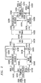
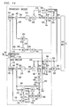
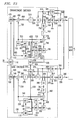
- Fig. C3 is a block diagram of a two layer video codec with base layer progressive, enhancement layer progressive, and adaptive channel sharing, arranged in accordance with the principles of this invention.
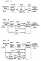
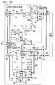
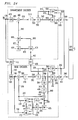
- Fig. C4 is a block diagram of a two layer video codec with base layer progressive, enhancement layer progressive, and adaptive channel sharing, arranged in accordance with the principles of this invention.
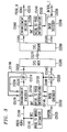
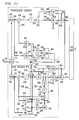
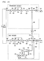
- Fig. C5 is a block diagram of a two layer video codec with base layer interlaced, enhancement layer progressive, and adaptive channel sharing, arranged in accordance with the invention.
- Fig. C5a is a block diagram of a progressive to interlaced decimator.
- Fig. C5b is a block diagram of a spatio-temporal low-pass filter.
- Fig. C5c is a block diagram of a motion adaptive spatio-temporal low-pass filter.
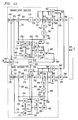
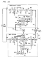
- Fig. C6 is a block diagram of a two layer video codec with base layer interlaced, enhancement layer interlaced, and adaptive channel sharing, arranged in accordance with the principles of this invention.
- Fig. C6a is a block diagram of a progressive to two-interlaced converter.
- Fig. C6b is a block diagram of a two-interlaced to progressive converter.
- Fig. ED shows an example of the frame reorganizer block "ORG" of the encoder and decoder block diagrams mentioned above.
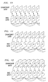
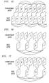
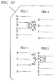
- Fig. F2 shows progressive to interlace conversion, in accordance with this invention.
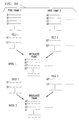
- Fig. F3 shows the operation of decimation for progressive to interlace conversion, arranged in accordance with this invention.
- Fig. F4 shows the operation of interpolation for interlace to progressive conversion, arranged in accordance with this invention.
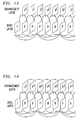
- Fig. F5 shows the operation of progressive to two-interlace conversion, arranged in accordance with this invention.
- Fig. F6 shows the operation of two-interlace to progressive conversion, arranged in accordance with this invention.
- Fig. C3 shows an illustrative spatially scalable system in accordance with this invention using a base layer consisting of lower resolution, progressive television.
- current FCC plans call for a base layer active video of 1280 pels, 720 scan lines, 60 Hz frame rate, 1:1 progressive.
- the video input is at the same frame rate, but has a higher resolution.
- one plan calls for up to 1920 pels, 960 lines, 60 Hz, 1:1 progressive.
- Another plan calls for up to 1920 pels, 1080 lines, 60 Hz, 1:1 progressive.
- Such progressive high resolution video enters the circuit of C3 on bus c3100 and passes to a spatial decimator c3120, where it may be low-pass filtered before reducing the number of pels to a lower base-layer resolution.
- the decimated base layer video is then output on bus c3130 and passes to a base encoder c3140, which outputs a typically variable bit-rate coded bit-stream on bus c3230.
- Base encoder c3140 also outputs a replica decoded base layer video signal on bus c3150, which passes to a spatial interpolator c3160. Spatial interpolator c3160 increases the number of pels per frame using any interpolation method well known in the art.
- This "upsampled" video is output on bus c3170 and passes to an enhancement encoder c3180, which outputs a typically variable bit-rate coded bit-stream on bus c3250.
- Enhancement encoder c3180 utilizes the upsampled video on bus c3170 as a prediction, in order to increase the efficiency of coding the full resolution progressive video input on bus c3100. An example of such encoding is described below.
- the two variable-rate bit-streams on buses c3230 and c3220 pass to buffers c3190 and c3210, respectively.
- buffers c3190 and c3210 are typically read out of the buffers at a different instantaneous rate than 4 bits are written into the buffers. Because of this, there is the possibility that overflow or underflow might occur.
- buffer c3190 outputs a fullness signal on bus c3200
- buffer c3210 outputs a fullness signal on bus c3225.
- buffer c3190 appearing on bus c3200 passes to both the base encoder c3140 and the enhancement encoder c3180.
- Base encoder c3140 utilizes this fullness signal to control the data flow into Buffer c3190 according to any method of controlling data flow well known in the art.
- enhancement encoder c3180 utilizes both buffer fullness signals in controlling the data flow into buffer c3210. For example, it may utilize the sum of the two fullnesses. Also, for example, if at any time Buffer c3190 were deemed too full, then enhancement encoder c3180 could cease producing data altogether for the enhancement layer, thereby allocating the entire transmission bit-rate to the base layer.
- Buffers c3190 and c3210 are read out of Buffers c3190 and c3210 on buses c3240 and c3250, respectively, under control of Systems Multiplexer c3250, which typically combines the two bit-streams in preparation for transmission on Channel c3260.
- the two bit-streams could be sent on two separate and independent channels.
- the decoded base layer video on bus c3310 also passes to spatial interpolator c3320, which is a duplicate of the interpolator c3150 and which produces an upsampled video on bus c3330. In the absence of transmission errors, the upsampled video on buses c3330 and c3170 are identical.
- Enhancement decoder c3340 utilizes the upsampled video on bus c3330 in conjunction with the enhancement layer bit-stream on bus c3290 to produce a decoded full resolution, progressive video on bus c3350. A detailed example of such decoding is described below.
- Fig. C4 shows another version of the invention where the base layer comprises a progressive video signal at full resolution, but at half the frame rate of the original.
- Current FCC plans call for a "film" mode of perhaps up to 1920 pels, 1080 lines, 30 Hz frame rate, 1:1 progressive.
- the system of Fig. C4 comprises a temporal demultiplexer c4130 which is a simple switching mechanism that routes alternate frames of progressive input video to output buses c4120 and c4110.
- a base encoder c4140 may operate in essentially the same way as the base encoder C3140 in Fig. c3, except that it codes full resolution video at half the frame rate.
- a replica decoded base layer video is output on bus c4180 that is full resolution.
- the enhancement encoder c4160 operates in exactly the same way as the enhancement encoder C3180 in Fig. c3. However, in this case the prediction picture on bus c4150 is temporally shifted from the video frames on bus c4120 that are to be encoded. For this reason a simple coding of the difference is not the most efficient method. An example, encoding is described below.
- An enhancement decoder c4290 produces a full resolution, half frame-rate video on bus c4340. These frames occur temporally at times half way between the frame times of the base layer video on bus c4320. The details of an example of such decoding is described below.
- a temporal multiplexor c4330 may comprise a simple switching mechanism that alternately feeds the frames on busses c4320 and c4340 to the output bus c4350 to provide a full resolution, full frame rate, progressive video.
- Fig. C5 shows another example of the invention where the base layer comprises an interlaced signal at full resolution, but at half the frame rate of the original progressive input.
- Current FCC plans call for an interlace mode of perhaps up to 1920 pels, 1080 lines, 30 Hz frame rate, 2:1 interlaced.
- Progressive-to-interlace-decimator c5110 converts each pair of progressive frames on bus c5100 to a single interlaced frame and outputs the result on bus c5120. Apparatus and methods for converting progressive format video to interlace format video are described below.
- a base encoder c5130 operates in exactly the same way as the base encoder C3140 in Fig. C3, except that it codes full resolution interlaced video at half the frame rate.
- a replica decoded base layer video is output on bus c5140 that is full resolution, interlaced.
- Interlace-to-progressive interpolator c5150 converts each replica decoded interlaced frame input from bus c5140 into two progressive frames in a manner to be described below.
- the resulting upsampled progressive video is output on bus c5160 and fed to an enhancement encoder c5170.
- Enhancement encoder c5170 operates in exactly the same way as the enhancement encoder C3180 in Fig. C3.
- Enhancement decoder c5360 utilizes the upsampled video on bus c5350 in conjunction with the enhancement layer bit-stream on bus c5290 to produce a decoded full resolution, full frame rate, progressive video on bus c5370.
- An example of such decoding is described in detail below.
- a fixed spatial-low-pass filter may be used on each progressive frame, as shown in Fig. C5a.
- each pair of progressive frames is converted to an interlaced frame by taking the odd numbered TV lines from the first frame of the progressive pair and the even numbered TV lines from the second frame of the progressive pair. This is accomplished by a subsampler C5a120, which discards alternate TV lines of each progressive frame.
- a line Buffer C5a130 serves to stretch the duration of each retained scan TV line by a factor of two to meet the timing requirements of the resulting interlaced video signal, which is output on bus C5a140.
- the buffer c5a140 is shown in Fig. c5a as a separate item, it may be incorporated into the operation of the base encoder that follows.
- the line subsampling operation is shown graphically in Fig. F2.
- the spatial filtering is normally employed only in the vertical dimension of each video frame.
- the combined filtering/subsampling operation is shown graphically in Fig. F3.
- an example 11-tap vertical filter is applied to each progressive video frame.
- the first filtered frame of each progressive pair is subsampled vertically to form the first field of the interlaced video frame.
- the second frame of each progressive pair becomes the second field of the interlaced frame.
- Fig. F3 for illustration is an example of a 7-tap vertical filter.
- the low-pass spatial filter C5a110 is needed to alleviate line flicker when displaying the interlaced frames on an interlaced display.
- the effect of the low-pass spatial filter is to significantly reduce the resolution by blurring, the visual information in the progressive frames. While this blurring is necessary to reduce line flicker in moving areas of the picture, it is unnecessary in stationary areas. Since text and computer graphics are often displayed without motion, they are particularly penalized by the low-pass spatial filter.
- a solution to this dilemma is to use an adaptive spatio-temporal low-pass filter that blurs only the moving parts of the picture and leaves the stationary parts at full resolution.
- One simple example is a three-tap finite-impulse-response (FIR) temporal filter.
- FIR finite-impulse-response
- Fig. C5b Such a filter is shown in Fig. C5b, where two progressive frame delays are used to form a weighted average of three progressive frames prior to TV line subsampling.
- Weighted averager C5b130 in a non-adaptive arrangement may apply a weight W, where 0 ⁇ W ⁇ 1, to the signal on line C5b160 corresponding to the middle frame, and a weight (1-W)/2 to each of the signals on lines C5b150 and C5b170 corresponding to the remaining two frames. This weighting is followed by a summation of the three weighted signals to form the filtered progressive video signal output on bus C5b140.
- Fig. C5c shows a motion adaptive filter that estimates the speed of motion and adjusts the weight W accordingly.
- Module C5c190 produces motion estimation signals. In many implementations, these signals may already be available as a result of the video coding process.
- the resulting motion vector MV is output on bus C5c210 and fed to a lookup table C5c200, which produces the weighting value W according to the amount of local motion.
- Weighting value W is output on line C5c180 and fed to the weighted averager C5c130, where it is used as described above for the apparatus of Fig. C5b.
- Fig. C6 shows another example of the invention where the base layer consists of an interlaced signal at full resolution, but half the frame rate of the original.
- a progressive-to-two-interlace-converter c6110 converts each pair of progressive frames on bus c6100 into two interlaced frames and outputs the results on buses c6120 and c6130.
- Fig. C6a shows an example of a progressive to two interlace converter.
- the operation is exactly the same as in Fig. C5a except that instead of discarding every other TV line, the alternate line switch C6a120 feeds each TV line to alternate outputs.
- the odd numbered TV lines are fed to output bus C6a170 (inter1_1)
- the even numbered TV lines are fed to C6a180 (inter1_2).
- the even numbered TV lines are fed to output bus C6a170 (inter1_1)
- the odd numbered TV lines to bus C6a180 (inter1_2).
- the operation of the progressive to two interlace converter is shown graphically in Fig. F5.
- Base encoder c6140 operates in exactly the same way as the base encoder C3140 in Fig. C3, except that it codes full resolution, interlaced video at half the frame rate.
- a replica decoded base layer video is output on bus c6150 and passed to enhancement encoder c6160 for use in coding the interlaced video input on bus c6120.
- Enhancement encoder c4160 operates in exactly the same way as the enhancement encoder C3180 in Fig. C3. However, in this case the prediction interlaced picture on bus c6150 is temporally shifted from the video on bus c4120 that is to be encoded. For this reason a simple coding of the difference is not the most efficient method. An example of encoding is described below.
- Enhancement decoder c6310 produces a full resolution, interlaced, half frame-rate video on bus c6360.
- the fields of this interlaced video are temporally displaced from the field times of the base layer interlaced video on bus c6320. An example of such decoding is described below.
- the decoding process produces an interlaced 30 Hz TV signal on each of the outputs C6340 and C6360.
- the two interlaced signals are then combined to produce a progressive 60 Hz TV signal by two interlace to progressive Converter c6360 in Fig. C6.
- Two-interlace to progressive Converter c6350 basically combines one field on bus c6360 with the temporally corresponding field on bus c6340 to form a progressive frame that is output on bus c6370. Its detailed operation is shown in Fig. C6b, which is basically the reverse of the operation of the apparatus of Fig. C6a. However, here there is no need for a filter. The processing is also shown graphically in Fig. F6.
- Fig. C6b produces a low-pass filtered progressive output. If only a fixed spatial low-pass filter were used, the quality of the progressive output might not be acceptable due to the overall blurriness. The quality may be markedly improved by using the aforementioned motion adaptive filters in module c6a110.
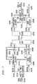
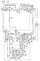
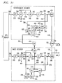
- Figure e12a shows an example of a base encoder and an enhancement encoder corresponding to the ones shown in of Fig. c3.
- High resolution video enters on bus e12a100.
- Spatial decimator e12a110 reduces the number of pels per frame, as described above, and outputs the base layer video on bus e12a120 to a base encoder.
- the base encoder may be a motion picture experts group (MPEG) arrangement, which for generality is shown as coding MPEG I, B and P pictures according to the structure graphically shown in Fig. G12A.
- MPEG motion picture experts group
- a frame reorganizer block ORG e12a130 reorders the input frames in preparation for coding and outputs the result on buses e12a140 and e12a150.
- An example of a frame reorganizer block is shown in Fig. ED.
- a motion estimator e12a170 examines the input frame on bus e12a150 and compares it with one or two previously coded frames. If the input frame is type I or P then one previous frame is used. If it is type B then two previously coded frames are used.
- Motion estimator e12a170 outputs motion vectors on bus e12a175 for use by motion compensator e12a180 and on bus e12a305 for use by a variable encoder e12a310.
- Motion compensator e12a180 utilizes the motion vectors and pels from previously coded frames to compute (for P and B type frames) a motion compensated prediction that is output on bus e12a230 which is passed to busses e12a240 and e12a250. For I type frames, the motion compensator e12a180 outputs zero pel values.
- Subtractor e12a160 computes the difference between the input frame on bus e12a140 and (for P and B types) the prediction frame on bus e12a250. The result appears on bus e12a260, is transformed by transformer e12a270 and quantized by quantizer e12a290 into typically integer values. Quantized transform coefficients pass on bus e12a300 to variable encoder e12a310 and inverse quantizer e12a380.
- Inverse quantizer e12a380 converts the quantized transform coefficients back to full range and passes the result via bus e12a390 to inverse transform e12a400, which outputs pel prediction error values on bus e12a410.
- Adder e12a420 adds the prediction error values on bus e12a410 to the prediction values on bus e12a240 to form the coded base layer pels on buses e12a430 and e12a440.
- switch e12a435 For I and P type frames, switch e12a435 passes the coded pels input on bus e12a430 to a nextpicture store e12a200via a bus e12a205. Simultaneously, the frame that was in nextpicture store e12a20 passes via bus e12a195 to previouspicture store e12a190. For B type frames, switch e12a435 takes no action, and the contents of picture stores e12a190 and e12a200 remain unchanged.
- picture stores e12a190 and e12a200 pass to motion estimator e12a170 and motion compensator e12a180 via buses e12a210 and e12a220 for use as needed.
- the quantizer step size qs that is used by quantizer e12a290 and inverse quantizer e12a380 is computed adaptively by quantization adapter e12a360 depending on the aforementioned buffer fullness indication on bus e12a350.
- the step size passes via bus e12a370 to quantizer e12a290 and inverse quantizer e12a380.
- the qs variable also passes to variable encoder e12a310 via bus e12a375.
- Variable encoder e12a310 encodes quantized transform coefficients input on bus e12a300, motion vectors input on bus e12a305 and quantizer step sizes qs input on bus e12a375 into a typically variable bit-rate bit-stream that is output on bus e12a320.
- This bit-stream on bus e12a320 then passes to a buffer e12a330 for temporary storage until it passes via bus e12a340 to the Systems Multiplexer. Also as described above, the fullness of buffer e12a330 is directed to the base encoder and the enhancement encoder of Fig. E12A via bus e12a350.
- the coded base layer frames pass via bus e12a440 to interpolator e12a450, as described above, where they are upsampled and passed to the enhancement encoder via bus e12a460.
- ORG e12a470 reorders the high resolution video frames to match the order of the base layer and outputs the result on bus e12a480.
- Subtractor e12a490 computes the difference between the input picture on bus e12a480 that is to be coded and a spatial prediction picture on bus e12a460.
- the prediction error is output on bus e12a500, transformed by transformer e12a510, quantized by quantizer e12a530 and passed via bus e12a540 to variable encoder e12a550.
- the quantizer step size used by the enhancement encoder is computed by quantization adapter e12a600 depending on the aforementioned two buffer fullnesses received on buses e12a350 and e12a590.
- the step size passes via bus e12a610 to quantizer e12a600 and to variable encoder e12a550 via bus e12a615.
- Variable encoder e12a550 encodes quantized transform coefficients input on bus e12a540 and quantizer step sizes qs input on bus e12a615 into a typically variable bit-rate bit-stream that is output on bus e12a560.
- This bit-stream on bus e12a560 then passes to buffer e12a570 for temporary storage until it passes via bus e12a580 to the Systems Multiplexer. As described above, the fullness of buffer e12a570 passes to the Enhancement Encoder via bus e12a590.
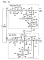
- Figure e12b shows an example of a base encoder and an enhancement encoder corresponding to those items shown generally in Fig. c4. Both the base and enhancement layers employ progressive signal at full resolution, but half the frame rate of the original. Alternately, coding can also be performed according to Fig. c6. The picture structure for this encoder is shown in Fig. g12b. For the purpose of explanation of encoding operations, assume coding according to Fig. c4.
- a temporal demultiplexer e12b110 may be a simple switching mechanism which routes alternate frames of progressive input to output buses e12b115 and e12b120, respectively.
- the base encoder in Fig. E12B operates in exactly the same way as the base encoder in Fig. e12a, except that it codes full resolution video at half the frame rate.
- a replica decoded base layer video is output on bus e12b440 that is full resolution.
- the enhancement encoder in Fig. E12B is similar to that of Fig. e12a. However, in this case, the prediction picture on bus e12b440 is temporally shifted from the video frames on bus e12b115 that are to be encoded. For this reason, a simple coding of the difference may not be the most efficient method.
- ORG e12b470 reorders the high resolution video frames to match the order of the base layer and outputs the result on buses e12b480 and e12b485.
- the base layer prediction picture on bus e12b440 first enters a transition store e12b620 whose contents are made available on bus e12b630 to motion estimator e12b640 and motion compensator e12b655.
- Motion estimator e12b640 examines the input frame on bus e12b485 and compares it with the base layer prediction frame on bus e12b630. Motion estimator e12b640 outputs motion vectors on bus e12b650 for use by motion compensator e12b655 and on bus e12b670 for use by variable encoder e12b550. Motion compensator e12b655 utilizes the motion vectors and pels from the base layer prediction frame to compute a motion compensated prediction that is output on bus e12b460 and passes to Subtractor e12b490.
- Fig. F12B The remaining operations of the Encoding operation of Fig. F12B are identical to those of Fig. e12a, except that variable encoder e12b550 inserts the motion vectors on bus e12b670 into the output bit-stream.
- Figure e12d shows an example of a base encoder and enhancement encoder corresponding to those items in the system of Fig. c4. Both the base and enhancement layers employ progressive signal at full resolution, but half the frame rate of the original. Alternately, coding can also be performed according to Fig. c6. The picture structure for this encoder is shown in Fig. g12d. For the purpose of explanation of encoding operations, assume coding according to Fig. c4.
- Temporal demultiplexer e12d110 may be a simple switching mechanism that routes alternate frames of progressive input to output buses e12d115 and e12d120, respectively.
- the base encoder in Fig. E12D operates in the same way as the base encoder in Fig. e12b, except for the replica base layer video, which is described below.
- the enhancement encoder of Fig. E12D has several differences compared with that of Fig. e12b.
- First, the enhancement layer video frames are not reordered prior to encoding. This means that the decoded base layer frames that are to be used as predictions are not in the correct order and must be reordered back to the original camera order.
- switch e12d810 After the encoding of a B type frame in the base layer, switch e12d810 is in the "B" position which routes the B frame from the output of adder e12d420 via bus e12d440 to its output on bus e12d815. During the encoding of I and P type frames, switch e12d810 is in the "A" position and routes previously coded frames from bus e12d210 via bus e12d800 so that they match temporally with the frames being encoded in the enhancement layer.
- the enhancement layer video on bus e12d115 is not reordered prior to encoding.
- delay e12d470 delays the enhancement layer video on bus e12d115 in order to temporally match the replica decoded base layer video on bus e12d815.
- the delayed enhancement layer video passes to a subtractor e12d490 and a motion estimator e12d640 via buses e12d480 and e12d485, respectively.
- the base layer prediction picture on bus e12d815 enters a transition store e12d620 whose contents are made available on bus e12d630 to the motion estimator e12d640 and a motion compensator e12d655.
- Motion estimator e12d640 examines the enhancement layer input frame on bus e12d485 and compares it with the base layer prediction frame on bus e12d630. Motion estimator e12d640 outputs motion vectors on bus e12d650 for use by the motion compensator e12d655 and on bus e12d670 for use by a variable encoder e12d550. Motion compensator e12d655 utilizes the motion vectors and pels from the base layer prediction frame to compute a motion compensated prediction that is output on bus e12d690 and passes to weighter e12d710 on bus e12d690.
- Motion estimator e12d640 also examines the enhancement layer input frame on bus e12d485 and compares it with the previously coded enhancement layer frame on bus e12d680 to compute additional motion vectors. Motion estimator e12d640 outputs these additional motion vectors also on bus e12d650 for use by motion compensator e12d655 and on bus e12d670 for use by variable encoder e12d550. Motion compensator e12d655 utilizes these motion vectors and pels from the enhancement layer prediction frame on bus e12d680 to compute another motion compensated prediction that passes to the weighter e12d710 on bus e12d700.
- Weighter e12d710 computes a weighted average of the two predictions input on buses e12d690 and e12d700 and outputs the result on buses e12d720 and e12d730 to subtractor e12d490 and adder e12d780, respectively.
- the weighting may be fixed, or it may adapt to such factors as the amount on motion in the scene, scene changes, etc.
- the weights could be limited to a finite set to minimize transmission overhead. Or the weights could be limited to 0 and 1, in which case the Weighter becomes a simple switch that passes either the input from bus e12d690 or the input from bus e12d700.
- the prediction error is calculated by subtractor e12d490, transformed by transformer e12d510, quantized by quantizer e12d530, encoded along with the quantizer step size qs and motion vector mv by variable encoder e12d550, sent to buffer e12d570, and then sent to the systems multiplexer.
- the decoded enhancement layer video which is needed for motion compensation of the next enhancement layer frame, is calculated in the same way as in the base layer, except that there are no B-type frames. Specifically, the quantized transform coefficients are converted to full range by inverse quantizer e12d740, converted to prediction error pel values by inverse transform e12d760, added to the motion compensated prediction by adder e12d780, and passed to the previous frame store e12d660 for use in motion estimation of the next frame.
- Figure e12e shows an example of a base encoder and an enhancement encoder corresponding to those in Fig. c4. Both the base and enhancement layers employ progressive signal at full resolution, but at half the frame rate of the original. Alternately, coding can also be performed according to Fig. c6. The picture structure for this encoder is shown in Fig. g12e. For the purpose of illustrative explanation of encoding operations, assume coding according to Fig. c4.
- High resolution and frame rate video enters on bus e12e100.
- the decimator e12e110 is temporal demultiplexer, a simple switching mechanism that routes alternate frames of progressive input video to output buses e12e115 and e12e120, respectively.
- the interpolator e12e450 is a 1:1 upsampler (alternately, there is no need for upsampling in some examples).
- the Base Encoder operates in exactly the same way as in Fig. e12b.
- a replica decoded base layer video is output on bus e12e440 that is full resolution.
- the Enhancement Encoder is similar to that of Fig. e12b. It, however, uses bidirectional prediction from base layer.
- Delay e12e470 delays the high resolution video frames of the enhancement layer.
- the base layer prediction picture on bus e12e440, as well as contents of picture stores e12e210 and e12e220 on respective buses e12e800 and e12e805, are available at switch e12e810.
- specific two out of three available base layer prediction frames at the input of switch e12e810 are necessary in the enhancement layer and pass via a 1:1 interpolator e12e450 to switch e12e605 and enter transition stores e12e620 and e12e625 both of whose contents are made available on bus e12e630 and bus e12e635 to motion estimator e12e640 and motion compensator e12e655.
- switch e12e810 is in the "C" position and routes previously coded frames from bus e12e210 via bus e12e800 and through the switch e12e815 to bus e12e820 and further through switch e12e605 which is in "B" position to frame store e12e620.
- switch e12e810 After the encoding of a B1 frame, switch e12e810 is in the "A” position and routes the B1 frame from the output of the adder e12e420 via bus e12e440 to its output on bus e12e815 and through the switch e12e605 which is in "A" position to the frame store e12e625. At this time, encoding of the first I2 frame is accomplished. After the encoding of a B2 frame, switch e12e810 is in the "A” position and routes the B2 frame from the output of adder e12e420 via bus e12e440 to its output on bus e12e815 and through the switch e12e605 which is in "B" position to frame store e12e620.
- Motion estimator e12e640 examines the input frame on bus e12e485 and compares it with the base layer predictions on bus e12e630 and on bus e12e635. Motion estimator e12e640 outputs motion vectors on bus e12e650 for use by motion compensator e12e655. Motion vectors are also made available for use by a variable encoder e12e550. Motion compensator e12e655 utilizes the motion vectors and pels from the two base layer prediction frames to compute a motion compensated prediction that is output on bus e12e460 and passes to subtractor e12e490.
- Figure e12g shows an example of a base encoder and an enhancement encoder corresponding to those in Fig. c4. Both the base and enhancement layers employ progressive signal at full resolution, but at half the frame rate of the original. Alternately, coding can also be performed according to Fig. c6. The picture structure for this encoder is shown in Fig. g12g. For the purpose of illustrative explanation of encoding operations, assume coding according to Fig. c4.
- High resolution and frame rate video enters on bus e12g100.
- the decimator is e12g110 is a temporal demultiplexer, a simple switching mechanism that routes alternate frames of progressive input video to output buses e12g115 and e12g120, respectively.
- the interpolator, e12g450 is a 1:1 upsampler.
- the base encoder in Fig. e12g operates in the same way the base encoder in Fig. e12e operates.
- the enhancement encoder has a notable difference compared with the enhancement encoder of Fig. e12e since it allows not only base layer frames as predictions but also temporal prediction from the enhancement layer.
- the base layer prediction picture on bus e12g440, as well as contents of picture stores e12g210 and e12g220 on respective buses e12g800 and e12g805, are available at switch e12g810.
- specific two out of three available base layer prediction frames at the input of switch e12g810 are necessary in the enhancement layer and pass via a 1:1 interpolator e12g450 to switch e12g605 and enter transition stores e12g620 and e12g625 both of whose contents are made available on bus e12g630 and bus e12g635 to motion estimator e12g640 and motion compensator e12g655.
- switch e12g810 is in the "C" position and routes previously coded frames from bus e12g210 via bus e12g800 and through the switch e12g815 to bus e12g820 and further through switch e12g605, which is in "B", position to frame store e12g620.
- switch e12g810 After the encoding of a B1 frame, switch e12g810 is in the "A" position and routes the B1 frame from the output of adder e12g420 via bus e12g440 to its output on bus e12g815 and through the switch e12g605 which is in the "A" position to frame store e12g625.
- encoding of the first I2 frame is accomplished, coded frame appears via bus e12g790 and is stored in frame store e12g660 to be used for prediction of the first P2 frame.
- switch e12g810 After the encoding of a B2 frame, switch e12g810 is in the "A" position and routes the B2 frame from the output of adder e12e420 via bus e12g440 to its output on bus e12g815 and through the switch e12g605, which is in "B" position, to frame store e12g620. Now the encoding of first P2 frame is accomplished, the coded frame appears via bus e12g790 and is stored in frame store e12g660 to be used for prediction of the second P2 frame.
- the contents of picture store e12g200 are routed on bus e12g800 and through switch e12g810 which is in the "B" position to switch e12g605, which is in the " A” position, and to frame store e12g625.
- the coded frame appears via bus e12g790 and is stored in frame store e12g660 to be used for prediction the next P2 frame. This process repeats itself for coding of subsequent frames.
- Motion estimator e12g640 examines the enhancement layer input frame on bus e12g485 and compares it with the base layer prediction frames on bus e12g630 and bus e12g635. Motion estimator e12g640 outputs motion vectors on bus e12g650 for use by motion compensator e12g655 and by variable encoder e12g550. Motion compensator e12g655 utilizes the motion vectors and pels from the base layer prediction frames to compute a motion compensated prediction that is output on bus e12g690 and passes to weighter e12g710 on bus e12g690.
- Motion estimator e12g640 also examines the enhancement layer input frame on bus e12g485 and compares it with the previously coded enhancement layer frame on bus e12g680 to compute additional motion vectors. Motion estimator e12g640 outputs these additional motion vectors also on bus e12g650 for use by motion compensator e12g655 and for use by variable encoder e12g550. Motion xompensator e12g655 utilizes these motion vectors and pels from the enhancement layer prediction frame on bus e12g680 to compute another motion compensated prediction that passes to weighter e12g710 on bus e12g700.
- Weighter e12g710 computes a weighted average of the two predictions input on buses e12g690 and e12g700 and outputs the result on buses e12g720 and e12g730 to subtractor e12g490 and adder e12g780, respectively.
- the weighting may be fixed, or it may adapt to such factors as the amount on motion in the scene, scene changes, and the like.
- the weights could be limited to a finite set to minimize transmission overhead. Or the weights could be limited to 0 and 1, in which case the weighter becomes a simple switch that passes either the input from bus e12g690 or the input from bus e12g700.
- the prediction error is calculated by subtractor e12g490, transformed by transformer e12g510, quantized by quantizer e12g530, encoded along with the quantizer step size qs and motion vector mv by variable encoder e12g550, sent to buffer e12g570 and thence to the systems multiplexer.
- the decoded enhancement layer video which is needed for motion compensation of the next enhancement layer frame, is calculated in the same way as in the base layer, except that there are no B-type frames. Specifically, the quantized transform coefficients are converted to full range by inverse quantizer e12g740, converted to prediction error pel values by inverse transform e12g760, added to the motion compensated prediction by adder e12g780 and passed to the previous frame store e12g660 for use in motion estimation of the next frame.
- Figure e12h shows an example of a base encoder and an enhancement encoder corresponding to those of Fig. c4. Both the base and enhancement layers employ a progressive signal at full resolution, but at half the frame rate of the original. Alternately, coding can also be performed according to Fig. c6. The picture structure for this encoder is shown in Fig. g12h. For the purpose of illustrative explanation of encoding operations, assume coding according to Fig. c4.
- decimator e12h110 is a temporal demultiplexer, a simple switching mechanism that routes alternate frames of progressive input video to output buses e12h115 and e12h120, respectively.
- the interpolator e12h450 is a 1:1 upsampler (alternately, there may be no need for upsampling).
- the base encoder in Fig. e12h operates in the same way that the base encoder of Fig. e12d operates.
- the enhancement encoder has a very similar operation to that of the base encoder, except that it uses a weighted combination of motion compensated prediction from the enhancement layer with motion compensated prediction from the base layer.
- ORG e12h470 reorders the high resolution video frames to match the order of the base layer and outputs the result on buses e12h480 and e12h485.
- Motion estimator e12h640 examines the enhancement layer input frame on bus e12h485 and compares it with the base layer prediction frame on bus e12h630. Motion estimator e12h640 outputs motion vectors on bus e12h650 for use by motion compensator e12h655 and by variable encoder e12h550. Motion compensator e12h655 utilizes the motion vectors and pels from the base layer prediction frame to compute a motion compensated prediction that is output on bus e12h690 and passes to weighter e12h710 on bus e12h690.
- Motion estimator e12h640 also examines the enhancement layer input frame on bus e12h485 and compares it with the previously coded enhancement layer frame on bus e12h680 to compute additional motion vectors. Motion estimator e12h640 outputs these additional motion vectors also on bus e12h650 for use by motion compensator e12h655 and for use by variable encoder e12h550. Motion compensator e12h655 utilizes these motion vectors and pels from the enhancement layer prediction frame on bus e12h680 to compute another motion compensated prediction that passes to weighter e12h710 on bus e12h700.
- Weighter e12h710 computes a weighted average of the two predictions input on buses e12h690 and e12h700 and outputs the result on buses e12h720 and e12h730 to subtractor e12h490 and adder e12h780, respectively.
- the weighting may be fixed, or it may adapt to such factors as the amount on motion in the scene, scene changes, and the like.
- the weights could be limited to a finite set to minimize transmission overhead. Or the weights could be limited to 0 and 1, in which case the weighter becomes a simple switch that passes either the input from bus e12h690 or the input from bus e12h700.
- the remaining operations of the enhancement encoding are identical to those of the base layer, except for the quantization adaptation e12h600 which operates in exactly the same way as it does in Figs. e12a and Fig. e12b.
- the prediction error is calculated by subtractor e12h490, transformed by transformer e12h510, quantized by quantizer e12h530, encoded along with the quantizer step size qs and motion vector mv by variable encoder e12h550, sent to buffer e12h570 and thence to the systems multiplexer.
- Figure e12i shows an example of a base encoder and an enhancement encoder corresponding to those of Fig. c5.
- the base layer employs an interlaced signal derived from the progressive original and the enhancement layer employs progressive signal at full resolution.
- the picture structure for this encoder is shown in Fig. g12i.
- High resolution and high frame rate video enters on bus e12i100.
- the decimator e12i110 is a progressive to interlace converter according to Fig. F3 and Fig. C5a as described earlier; its output is routed to bus e12h120 while the undecimated progressive source is input as is to the enhancement encoder.
- the interpolator e12i450 performs the inverse operation of the decimator, ie, interlace to progressive conversion; this operation is explained earlier according to Fig. F4.
- base encoder follows exactly the description of Fig. e12b, the only difference being that the input to base encoder is interlaced rather than the progressive input as in Fig. e12b.
- the enhancement encoder is quite similar to that of Fig. e12a, the only difference being that it operates at twice the frame rate of base encoder.
- ORG e12i470 reorders pairs of high resolution video frames to match the order of each base layer frame and outputs the result on buses e12i480 and e12i485. It is important to notice that the base layer here processes interlaced frames that appear at half the frame rate of the enhancement layer.
- the output of the base encoder comprising interlaced frames, is available at bus e12i440 and passes through interlaced to progressive converter e12i450.
- the resulting signal on line e12i460 is applied to a switch e12i605 whose output e12i860 either passes directly to a next switch e12i880 or to a frame store e12i620 and on to bus e12i870 as the second input to switch e12i880. This is so because, after interlaced to progressive conversion, each interlaced frame results in two progressive frames, only one of which can be output directly on line e12i890 while the other one is stored for prediction of a next enhancement layer picture by storing it in e12i620 until it is needed.
- Subtractor e12i490 computes the difference between the input picture on bus e12i480 that is to be coded and the prediction picture on bus e12i890.
- the prediction error is output on bus e12i500, transformed by transformer e12i510, quantized by quantizer e12i530, and passed via bus e12i540 to variable encoder e12i550.
- the quantizer step size used by the enhancement encoder is computed by quantization adapter e12i600 depending on the two buffer fullnesses on buses e12i350 and e12i590.
- the step size passes via bus e12i610 to quantizer e12i600 and to variable encoder e12i550 via bus e12i615.
- Variable encoder e12i550 encodes quantized transform coefficients input on bus e12i540 and quantizer step sizes qs input on bus e12i615 into a typically variable bit-rate bit-stream that is output on bus e12i560.
- the prediction picture for first of each pair of progressive frames on bus e12i480 comes directly from bus e12i860, and for the second progressive frame from bus e12i870. This process is repeated for subsequent frames.
- Figure e12j shows an example of a base encoder and an enhancement encoder corresponding to those of Fig. c5.
- the base layer employs an interlaced signal derived from the progressive original and the enhancement layer employs progressive signal at full resolution.
- the picture structure for this encoder is shown in Fig. g12j.
- High resolution and high frame rate video enters on bus e12j100.
- the decimator e12j110 is a progressive to interlace converter according to Fig. F3 and Fig. C5a as described earlier; its output is routed to bus e12j120 while the undecimated progressive source is input as is to the enhancement encoder.
- the interpolator e12j450 performs the inverse operation of the decimator, ie, interlace to progressive conversion; this operation is explained earlier according to Fig. F4.
- base encoder follows exactly the description of Fig. e12d, the only difference being that the input to the base encoder is interlaced rather then the progressive input as in Fig. e12d.
- Delay e12j470 delays the high resolution video frames at the input of the enhancement encoder. It is important to notice that the base layer here processes interlaced frames that appear at half the frame rate of enhancement layer.
- the enhancement encoder is an extension of encoder of Fig. e12a and uses not only the prediction from the base layer but also uses motion compensated prediction from the enhancement layer as in Fig. e12d. Moreover, it operates at twice the frame rate of base encoder in Fig. e12i.
- the output of the base encoder comprising interlaced frames is available at bus e12j440 and passes through interlaced to progressive converter e12j450.
- the resulting signal on line e12j460 is applied to a switch e12j605 whose output e12j860 either passes directly to a next switch e12j880 or to frame store e12j620 and on to bus e12j870 as the second input to switch e12j880. This is so because, after interlaced to progressive conversion, each interlaced frame results in two progressive frames, only one of which can be output directly on line e12j890 while the other one is stored for prediction of a next enhancement layer picture by storing it in e12j620 until it is needed.
- Reordering of frames of the base layer is accomplished via a switch e12j810.
- switch e12j810 After the encoding of a B type frame in the base layer, switch e12j810 is in the "B" position and routes the B- frame from the output of adder e12j420 via bus e12j440 to its output on bus e12j815.
- switch e12j810 is in the "A" position and routes previously coded frames from bus e12j210 via bus e12j800 so that they match temporally with the frame being encoded in the enhancement layer.
- the enhancement layer video on bus e12j100 is not reordered prior to encoding.
- delay e12d470 delays the enhancement layer video on bus e12j100 in order to temporally match the replica decoded base layer video on bus e12j815.
- the delayed enhancement layer video passes to subtractor e12j490 and motion estimater e12j640 via buses e12j480 and e12j485, respectively.
- the base layer prediction picture on bus e12j815 enters interlace to progressive interpolator e12j450 and then to bus e12j820 which is applied to a switch e12j605 whose output e12j660 either passes directly to a next switch e12i880 or to a frame store e12j620 and on to bus e12j670 as the second input to a switch e12i880.
- Motion estimator e12j640 examines the enhancement layer input frame on bus e12j485 and compares it with the previously coded enhancement layer frame on bus e12j680 to compute additional motion vectors. Motion estimator e12j640 outputs these additional motion vectors also on bus e12j650 for use by motion compensator e12j655 and for use by variable encoder e12j550. Motion compensator e12j655 utilizes these motion vectors and pels from the enhancement layer prediction frame on bus e12j680 to compute motion compensated prediction that passes to weighter e12j710 on bus e12j700.
- Weighter e12j710 computes a weighted average of the two predictions input on buses e12j890 and e12j700 as described for the encoder of Fig. e12d.
- the remaining operations of the enhancement encoding are identical to those of the base layer, except for the quantization adaptation e12j600 which operates in exactly the same way as in Figs. e12a and e12b.
- Figure d12a shows an example of base decoder and an enhancement decoder corresponding to those of Fig. c3.
- the base decoder may be an MPEG decoder, which for generality is shown as decoding I, B and P pictures according to the structure of Fig. G12A.
- the received bit-stream on bus d12a340 passes from the systems demultiplexer to a buffer d12a330 for temporary storage until it passes via bus d12a320 to a variable decoder d12a310.
- Variable decoder d12a310 decodes quantized transform coefficients which are then output on bus d12a300, quantizer step sizes qs which are then output on bus d12a370, and motion vectors which are then output on buses d12a175 and d12a305.
- Motion compensator d12a180 utilizes the motion vectors on bus d12a175 and pels from previously decoded frames on buses d12a210 and d12a220 to compute (for P and B type frames) a motion compensated prediction that is output on bus d12a240. For I type frames, motion compensator d12a180 outputs zero pel values.
- Qs signals pass from variable decoder d12a310 via bus d12a370 to inverse quantizer d12a380.
- Quantized transform coefficients pass on bus d12a300 from variable decoder d12a310 to inverse quantizer d12a380.
- Inverse quantizer d12a380 converts the quantized transform coefficients back to full range and passes the result via bus d12a390 to inverse transform d12a400, which outputs pel prediction error values on bus d12a410.
- Adder d12a420 adds the prediction error values on bus d12a410 to the prediction values on bus d12a240 to form the decoded base layer pels on buses d12a430, d12a435, and d12a440.
- switch d12a435 passes the decoded pels on bus d12a430 via bus d12a205 to the nextpicture store d12a200. Simultaneously, the frame that was in nextpicture store d12a200 passes via bus d12a195 to previouspicture store d12a190.
- switch d12a435 takes no action, and the contents of picture stores d12a190 and d12a200 remain unchanged.
- picture stores d12a190 and d12a200 pass to motion estimator d12a170 and motion compensator d12a180 via buses d12a210 and d12a220 for use as needed by those elements.
- ORG d12a130 reorders the base layer decoded output frames on bus d12a435 in preparation for display on bus d12a120.
- the decoded base layer frames pass via bus d12a440 to interpolator d12a450, where they are upsampled and passed to the enhancement decoder via bus d12a460.
- the enhancement layer bit-stream passes from the Systems Demultiplexer to buffer d12a570 via bus d12a580 for temporary storage until it passes via bus d12a560 to the Variable Decoder d12a550.
- Variable decoder d12a550 decodes quantized transform coefficients output on bus d12a540 and quantizer step sizes qs output on bus d12a610. Quantizer step sizes qs pass from bus d12a610 to inverse quantizer d12a530.
- Quantized transform coefficients pass on bus d12a540 from variable decoder d12a550 to inverse quantizer d12a530.
- Inverse quantizer d12a530 converts the quantized transform coefficients on bus d12a540 back to full range and passes the result via bus d12a520 to inverse transform d12a510, which outputs pel prediction error values on bus d12a500.
- Adder d12a490 adds the prediction error values on bus d12a500 to the prediction values on bus d12a460 to form the decoded enhancement layer pels on bus d12a480.
- ORG d12a470 reorders the high resolution video frames on bus d12a480 to match the order of the base layer and outputs the result on bus d12a100 for display.
- Fig. d12b shows a base decoder and an enhancement decoder corresponding to the encoder apparatus of Fig. e12b. If coding is done following Fig. c4, both the base and enhancement layers use a progressive signal at full resolution, but at half the frame rate of the original. Alternately, if codec of Fig. c6 is employed, both the base and enhancement layer use interlaced signals. The picture structure for this decoder is shown in Fig. g12d. For the purpose of illustrative explanation of the operation of Fig. d12b, assume coding according to Fig. c4.
- the base decoder of Fig. D12B operates in exactly the same way as the base decoder in Fig. d12a, except that it decodes full resolution video at half the frame rate.
- a decoded base layer reordered video is output on buses d12b440, D12B140 an D12B430.
- the base layer video on bus 140 is reordered into camera order by ORG 130 and output on buses 120 and 125.
- the base layer video is passed to the base layer display via bus 120.
- the enhancement decoder in Fig. D12B is similar to that of Fig. d12a. However, in this case, the prediction picture on bus d12b440 is temporally shifted from the video frames on bus d12b115 that are to be decoded.
- the decoded base layer video is full resolution. Thus, there is no need for upsampling prior to delivery to the enhancement decoder.
- the base layer prediction picture on bus d12b440 first enters a transition store d12b620 whose contents are made available on bus d12b630 to motion compensator d12b655.
- the enhancement layer bit-stream passes from the systems demultiplexer to buffer d12b570 via bus d12b580 for temporary storage until it passes via bus d12b560 to the variable decoder d12b550.
- Variable decoder d12b550 decodes quantized transform coefficients which are output on bus d12b540, quantizer step sizes qs which are output on bus d12b610 and motion vectors which are output on buses d12b670 and d12b650. Quantizer step sizes qs pass from bus 610 to inverse quantizer 530.
- Motion compensator d12b655 utilizes the enhancement layer motion vectors on bus d12b650 and pels from the base layer prediction frame on bus d12b630 to compute a motion compensated prediction that is output on bus d12b460 and passes to adder d12b490.
- Quantized transform coefficients pass on bus d12b540 from variable decoder d12b550 to inverse quantizer d12b530.
- Inverse quantizer d12b530 converts the quantized transform coefficients on bus 540 back to full range and passes the result via bus d12b520 to inverse transform d12b510, which outputs pel prediction error values on bus d12b500.
- Adder d12b490 adds the prediction error values on bus d12b500 to the prediction values on bus d12b460 to form the decoded enhancement layer pels on bus d12b480.
- ORG d12b470 reorders the high resolution video frames on bus 480 to match the order of the base layer and outputs the result on bus d12b115.
- Temporal multiplexer d12b110 may be a simple switching mechanism that routes alternate frames of progressive input on buses d12b115 and d12b125, respectively, to output bus d12b100.
- Fig. d12d shows an example of a base decoder and an enhancement decoder corresponding to the encoder apparatus of Fig. e12d. If coding is done following Fig. c4, both the base and enhancement layers use a progressive signal at full resolution, but at half the frame rate of the original. Alternately, if codec of Fig. c6 is employed, both the base and enhancement layer use interlaced signal. The picture structure for this decoder is shown in Fig. g12d. For the purpose of illustrative explanation of operation of Fig. d12d, assume coding according to Fig. c4.
- the Base Decoder of Fig. D12D operates in the same way as in Fig. d12b, except for the reordering of the decoded base layer video, as mentioned above for the encoder e12d.
- the enhancement decoder of Fig. D12B has several differences compared with that of Fig. d12b, as mentioned above for encoder e12d. Since the enhancement layer video frames are not reordered prior to encoding, the decoded base layer frames that are to be used as predictions must be reordered by switch d12d810.
- switch d12d810 is in the "B" position and routes B-frames from the output of adder d12d420 via bus d12d440 to its output on bus d12d815.
- switch d12d810 is in the "A" position and routes previously coded frames from bus d12d210 via bus d12d800 so that they match temporally with the frames being decoded in the enhancement layer.
- the base layer prediction picture on bus d12d815 enters transition store d12d620 whose contents are made available on bus d12d630 to motion compensator d12d655.
- the enhancement layer bit-stream passes from the systems demultiplexer to buffer d12d570 via bus d12d580 for temporary storage until it passes via bus d12d560 to the variable decoder d12d550.
- Variable decoder d12d550 decodes quantized transform coefficients and outputs them on bus d12d540, quantizer step sizes qs and outputs them on bus d12d610 and motion vectors and outputs them on buses d12d670 and d12d650. Quantizer step sizes qs pass from bus d12d610 to inverse quantizer d12d740.
- Motion compensator d12d655 utilizes the enhancement layer motion vectors on bus d12d650 and pels from the base layer prediction frame on bus d12d630 to compute a motion compensated prediction that is output on bus d12d690 and passed to weighter d12d710.
- Motion compensator d12d655 also utilizes the enhancement layer motion vectors on bus d12d650 and pels from the previously decoded enhancement layer frame on bus d12d680 to compute a motion compensated prediction that is output on bus d12d700 and passed to weighter d12d710.
- Weighter d12d710 computes a weighted average of the two predictions input on buses d12d690 and d12d700 and outputs the result on buses d12d720 and d12d730 to subtractor d12d490 and adder d12d780, respectively.
- the weighting used in computing the prediction is the same as was used during the encoding process.
- the remaining operations of the enhancement decoding are identical to those of the Base Layer.
- the quantized transform coefficients on bus d12d540 are converted to full range by inverse quantizer d12d740, converted to prediction error pel values by inverse transform d12d760, added to the motion compensated prediction on bus d12d720 by adder d12d780, and outputted on buses d12d790 and d12d115 as decoded enhancement layer video.
- the video on bus d12d790 is passed to the previous frame store d12d660 for use in motion compensation of the next frame.
- the video on bus d12d115 is passed to the temporal multiplexer d12d110.
- Temporal demultiplexer d12d110 may be a simple switching mechanism that routes alternate frames of progressive input from input buses d12d115 and d12d120, respectively, to bus d12d100. High resolution video thus exits on bus d12d100.
- Fig. d12e shows the base decoder and enhancement decoder corresponding to the encoder apparatus of Fig. e12e. If coding is done following Fig. c4, both the base and enhancement layers use a progressive signal at full resolution, but at half the frame rate of the original. Alternately, if the codec of Fig. c6 is employed, both the base and enhancement layer use interlaced signal. The picture structure for this decoder is shown in Fig. g12e. For the purpose of illustrative explanation of Fig. d12e, assume coding according to Fig. c4.
- the Base Decoder operates in the same way as in Fig. d12d, except for the reordering of the decoded base layer video.
- the operation of the enhancement decoder is similar to that of Fig. d12b. Since the enhancement layer video frames are not reordered prior to encoding, the decoded base layer frames that are to be used as predictions must be reordered by switch d12d810.
- the base layer prediction picture on bus d12e430, as well as contents of picture stores d12e190 and d12e200 on respective buses d12e800 and d12e805 are available at switch d12e810.
- specific two out of three available base layer prediction frames at the input of switch d12e810 are necessary in the enhancement layer and pass via a 1:1 interpolator d12e450 to switch d12e605 and enter transition stores d12e620 and d12e625 both of whose contents are made available on bus d12e630 and bus d12e635 to motion compensator d12e655.
- switch d12e810 is in the "A" position and routes previously coded frames from bus d12e210 through the switch d12e810 and bus d12e815 to bus d12e820 and further through switch d12e605 which is in "B" position to frame store d12e620.
- switch d12e810 After the decoding of a B1 frame, switch d12e810 is in "B” position and routes the B1 frame from the output of adder d12e420 via bus d12e430 to its output on bus d12e815 and through the switch d12e605 which is in "A" position to frame store d12e625. At this time, decoding of the first I2 frame is accomplished. After the decoding of a B2 frame, switch d12e810 is in "B” position and routes B2 frame from the output of adder d12e420 via bus d12e430 to its output on bus d12e815 and through the switch d12e605 which is in "B" position to frame store d12e620.
- the quantized transform coefficients on bus d12e540 are converted to full range by inverse quantizer d12e740, converted to prediction error pel values by inverse transform d12e760, added to the motion compensated prediction on bus d12e720 by adder d12e780 and output on bus d12e115 as decoded enhancement layer video.
- the video on bus d12e115 is passed to converter d12e105, a temporal multiplexer switching mechanism that routes alternate frames of progressive input video from buses d12e115 and d12e120, respectively.
- High resolution and high frame rate video exits on bus d12e100.
- Fig. d12g shows the base decoder and enhancement decoder corresponding to the encoder apparatus of Fig. e12g. If coding is done following Fig. c4, both the base and enhancement layers use a progressive signal at full resolution, but at half the frame rate of the original. Alternately, if codec of Fig. c6 is employed, both the base and enhancement layer use interlaced signals.
- Fig. g12g The picture structure for this decoder is shown in Fig. g12g.
- Fig. d12g For the purpose of illustrative explanation of Fig. d12g, assume coding according to Fig. c4.
- the base decoder operates in the same way as the base decoder in Fig. d12e.
- the enhancement decoder has a noticeable difference compared with the enhancement decoder of Fig. d12e since it uses not only base layer frames as predictions but also temporal prediction from the enhancement layer.
- the base layer prediction picture on bus d12g430, as well as contents of picture stores d12g210 and d12g220 on respective buses d12g800 and d12g805 are available at switch d12g810.
- specific two out of three available base layer prediction frames at the input of switch d12g810 are necessary in the enhancement layer and pass via a 1:1 interpolator d12g450 to a switch d12g605 and enter transition stores d12g620 and d12g625 both of whose contents are made available on bus d12g630 and bus d12g635 to motion estimator d12g640 and motion compensator d12g655.
- switch d12g810 is in the "A" position and routes previous decoded frame from bus d12g210 via bus d12g800 and through the switch d12g815 to bus d12g820 and further through switch d12g605 which is in "B" position to frame store d12g620.
- switch d12g810 After the decoding of a B1 frame, switch d12g810 is in the "B" position and routes the B1 frame from the output of adder d12g420 via bus d12g440 to its output on bus d12g815 and through the switch d12g605 which is in the "A" position to frame store d12g625. At this time, decoding of the first I2 frame is accomplished, the decoded frame appears via bus d12g790 and is stored in frame store d12g660 to be used for prediction the first P2 frame.
- switch d12g810 After the decoding of B2 frame, switch d12g810 is in the "B" position and routes B2 frame from the output of adder d12e420 via bus d12g440 to its output on bus d12g815 and through the switch d12g605 which is in the "B" position to a frame store d12g620. Now that the decoding of first P2 frame is accomplished, the decoded frame appears via bus d12g790 and is stored in frame store d12g660 to be used for prediction of the second P2 frame.
- the contents of picture store d12g200 are routed on bus d12g800 and through switch d12g810, which is in the "C” position, to switch d12g605, which is in the "A” position, and to frame store d12g625.
- the coded frame appears via bus d12g790 and is stored in frame store d12g660 to be used for prediction the next P2 frame. This process repeats itself for coding of subsequent frames.
- Weighter d12g710 computes a weighted average of the two predictions input on buses d12g690 and d12g700 and outputs the result on buses d12g720 and d12g730 to adder d12g780.
- the quantized transform coefficients on bus d12g540 are converted to full range by inverse quantizer d12g740, converted to prediction error pel values by inverse transform d12g760, added to the motion compensated prediction on bus d12g720 by adder d12g780 and output on bus d12g480, after which, frames are reordered in d12g470 and output on d12g115 as decoded enhancement layer video.
- the video on bus d12e115 is passed to converter d12e105, a temporal multiplexer switch that routes alternate frames of progressive input video from buses d12e115 and d12e120, respectively. High resolution and high frame rate video exits on bus d12e100.
- Fig. d12h shows the base decoder and enhancement decoder corresponding to the encoder apparatus of Fig. e12h. If coding is done following Fig. c4, both the base and enhancement layers use a progressive signal at full resolution, but at half the frame rate of the original. Alternately, if codec of Fig. c6 is employed, both the base and enhancement layer use interlaced signals. The picture structure for this decoder is shown in Fig. g12h. For the purpose of illustrative explanation of Fig. d12h, we assume coding according to Fig. c4.
- the base decoder operates in the same way as the base decoder in Fig. d12d.
- the enhancement decoder has a very similar operation to that of the base decoder, except that it uses a weighted combination of motion compensated prediction from the enhancement layer with motion compensated prediction from the base layer.
- Motion compensator d12h655 utilizes the decoded motion vectors, and pels from the base layer prediction frame, to compute a motion compensated prediction that is output on bus d12h690 and passes to weighter d12h710 on bus d12h690. Motion compensator d12h655 also utilizes decoded motion vectors, and pels from the enhancement layer prediction frame, on bus e12h680, to compute another motion compensated prediction that passes to weighter e12h710 on bus e12h700.
- Weighter d12h710 computes a weighted average of the two predictions input on buses d12h690 and d12h700 and outputs the result on buses d12h720 to adder d12h780.
- the quantized transform coefficients on bus d12h540 are converted to full range by inverse quantizer d12h740, converted to prediction error pel values by inverse transform d12h760, added to the motion compensated prediction on bus d12h720 by adder d12g780 and output on bus d12h480, after which, frames are reordered in d12h470 and output on d12g115 as decoded enhancement layer video.
- the video on bus d12e115 is passed to converter d12e105, a temporal multiplexer switch that routes alternate frames of progressive input video from buses d12e115 and d12e120, respectively. High resolution and high frame video exits on bus d12e100.
- Fig. d12i shows the base decoder and enhancement decoder corresponding to the encoder apparatus of Fig. e12i. Coding is done following Fig. c5.
- the base layer thus uses interlaced signals derived from the progressive original and the enhancement layer uses a full resolution progressive original.
- the picture structure for this decoder is shown in Fig. g12i.
- the base layer prediction picture on bus d12i440 enters interlace to progressive interpolator d12i450 and then to bus d12i460 which is applied to a switch d12i605 whose output d12i860 either passes directly to next switch d12i880 or to frame store d12i620 and on to bus d12i870 as the second input to switch d12i880.
- enhancement decoder operates at twice the frame rate of the base decoder.
- Fig. d12j shows the base decoder and enhancement decoder corresponding to the encoder apparatus of Fig. e12j. Coding is done following Fig. c5.
- the base layer thus uses interlaced signals derived from the progressive original and the enhancement layer uses a full resolution original.
- the picture structure for this decoder is shown in Fig. g12j.
- this base decoder follows exactly the description of the base decoder of Fig. d12d, the only difference being that the output of the base decoder is interlaced rather than the progressive output as in Fig. d12d.
- switch d12j810 Reordering of frames of the base layer is accomplished via switch d12j810.
- switch d12j810 After the encoding of a B type frame in the base layer, switch d12j810 is in the "B" position and routes the B- frame from the output of adder e12j420 via bus e12j440 to its output on bus e12j815.
- switch e12j810 is in the "A" position and routes previously coded frames from bus e12j210 via bus e12j800 so that they match temporally with the frame being encoded in the enhancement layer.
- the base layer prediction picture on bus d12j815 enters interlace to progressive interpolator d12j450 and then is directed to bus d12j820 which is applied to a switch d12j605 whose output d12j860 either passes directly to next switch d12j880 or to frame store d12j620 and then on to bus d12j870 as the second input to switch d12j880.
- Motion Compensator d12j655 utilizes decoded motion vectors and pels from the enhancement layer prediction frame on bus d12j680 to compute a motion compensated prediction that passes to weighter d12j710 on bus d12j700.
- Weighter d12j710 computes a weighted average of the two predictions input on buses d12j890 and d12j700 as described for decoder of Fig. d12d.
- enhancement decoder operates at twice the frame rate of the base decoder.
- a picture structure is an arrangement of these picture types, and is identified by value of 'M', the distance between a P-picture and previous decoded reference picture, which is a P- picture except at the beginning of a Group-of-Pictures (GOP) where it is an I- picture.
- 'M' the distance between a P-picture and previous decoded reference picture
- GOP Group-of-Pictures
- 'N' the distance between corresponding I- pictures gives the length of a GOP.
- B- pictures are predicted noncausally and are outside the interframe coding loop of P- pictures.
- B-pictures are predicted using two references, an immediate previous decoded I- or P- picture, and an immediate next decoded P- or I- picture. The number of B- pictures between two reference pictures is given by value of 'M-1'.
- Fig. G12a shows picture structures for the base and the enhancement layers; the corresponding structures are applied to the base and the enhancement layer encoders.
- the enhancement layer simply consists of I- pictures (no temporal prediction within the same layer) but uses spatially interpolated base layer pictures for prediction. The base and the enhancement layer pictures occur at exactly the same temporal instants.
- the picture arrangement of Fig. G12a can be used, for example, for migration to progressive 960 line, 60 Hz frame rate video.
- a general block diagram of a codec employing this picture arrangement is shown in Fig. C3.
- the base layer in that example uses progressive format 720 line, 60 Hz frame rate video
- the enhancement layer uses progressive format 960 line, 60 H frame rate.
- Each base layer decoded picture is upsampled by a factor of 3:4 to yield prediction for each picture of the enhancement layer.
- the enhancement layer consists of I- pictures only with no temporal prediction of pictures within this layer.
- I1-pictures are like I- pictures in the sense that they do not employ temporal prediction within the same layer. However, they do employ motion compensated unidirectional prediction from the base layer.
- Fig. G12b shows picture structures for the base and the enhancement layers; the corresponding structures are applied to the base and the enhancement layer encoders.
- the enhancement layer simply consists of I1- pictures (no temporal prediction within the same layer) but uses the immediate previous base layer picture as reference for motion-compensated prediction.
- the picture arrangement of Fig. G12b also can be used for migration to progressive 960 line, 60 Hz video.
- a general block diagram of codecs employing this picture arrangement is shown in Fig. C4 and Fig. C6.
- the base layer uses progressive 960 line, 30 Hz, obtained by selecting only the even numbered frames from 60 Hz source
- the enhancement layer uses progressive 960 line, 30 Hz, obtained by selecting the odd numbered frames; the enhancement layer pictures thus occur at intermediate temporal instants of the base layer pictures.
- the base layer and enhancement layers both use interlaced 960 line, obtained by either fixed or adaptive progressive-to-two interlace conversion from 60 Hz progressive source.
- the enhancement layer pictures occur at same temporal frame instants as the base layer pictures though their field order in each frame is complementary to that in base layer.
- base layer pictures are labeled as even numbered frames and enhancement layer pictures as odd numbered frames.
- Each base layer decoded picture is used for prediction of the next picture in the enhancement layer.
- the enhancement layer consists of I1- pictures only with no temporal prediction of pictures within this layer.
- P1- pictures are like P- pictures in the sense that they employ unidirectional temporal prediction within the same layer. They, however, also employ motion compensated unidirectional prediction from the base layer.
- Fig. G12d shows picture structures for the base and the enhancement layers; the corresponding structures are applied to the base and the enhancement layer encoders.
- the picture arrangement of Fig. G12d can be used for migration to progressive 960 line, 60 Hz video.
- a general block diagram of codecs employing this picture arrangement is shown in Fig. C4 and Fig. C6.
- the base layer uses progressive, 960 line, 30 Hz, obtained by selecting only the even numbered frames from 60 Hz source.
- the enhancement layer uses progressive, 960 line, 30 Hz, obtained by selecting the odd numbered frames.
- the enhancement layer pictures thus occur at intermediate temporal instants of the base layer pictures.
- the base layer and enhancement layers both use interlaced 960 line video, obtained by either fixed or adaptive progressive-to-two interlace conversion from 60 Hz progressive source.
- the enhancement layer pictures occur at same temporal frame instants as the base layer pictures though their field order in each frame is complementary to that in base layer.
- base layer pictures are labeled as even numbered frames and enhancement layer pictures as odd numbered frames.
- Each base layer decoded picture is used for prediction of the next picture in the enhancement layer.
- the P1- pictures benefit from two predictions, motion compensated prediction with respect to the immediately previous odd-numbered decoded picture in the same layer as well as motion compensated prediction from the immediately previous even-numbered decoded picture in the base layer.
- I1- pictures introduced above for enhancement layer to what we call I2- pictures.
- the I2- pictures like I1- pictures do not employ temporal prediction within the same layer, however, they differ as they employ motion compensated bidirectional prediction instead of unidirectional prediction from the base layer.
- Fig. G12e shows such picture structures for the base and the enhancement layers; the corresponding structures are applied to the base and the enhancement layer encoders.
- the enhancement layer simply consists of I2- pictures (no temporal prediction within the same layer) but uses the immediate previous and the immediate next decoded base layer pictures as reference for motion-compensated prediction.
- the picture arrangement of Fig. G12e can be used for migration to progressive, 960 line, 60 Hz video.
- a general block diagram of codecs employing this picture arrangement is shown in Fig. C4 and Fig. C6.
- the base layer uses progressive 960 line, 30 Hz video, obtained by selecting only the even numbered frames from a 60 Hz source.
- the enhancement layer uses progressive, 960 line, 30 Hz video, obtained by selecting the odd numbered frames from that 60Hz source.
- the enhancement layer pictures thus occur at intermediate temporal instants of the base layer pictures.
- the base layer and enhancement layers both use interlaced 960 line, obtained by either fixed or adaptive progressive-to-two interlace conversion from 60 Hz progressive source.
- the enhancement layer pictures occur at same temporal frame instants as the base layer pictures though their field order in each frame is complementary to that in base layer.
- base layer pictures are labeled as even numbered frames and enhancement layer pictures as odd numbered frames.
- Each base layer decoded picture is used for prediction of the next picture in the enhancement layer.
- the enhancement layer consists of I2- pictures which do not use any temporal prediction within this layer but employ bidirectional motion compensated prediction with respect to base layer.
- P1- pictures introduced above for enhancement layer employ temporal prediction within the same layer. However they differ because they use motion compensated bidirectional prediction instead of unidirectional prediction from the base layer.
- Fig. G12g shows such picture structures for the base and the enhancement layers; the corresponding structures are applied to the base and the enhancement layer encoders.
- the first picture in enhancement layer thus is an I2- picture and is followed by remaining P2- pictures.
- the picture arrangement of Fig. G12g can be used for migration to progressive format, 960 line, 60 Hz frame rate video and the like.
- a general block diagram of codecs employing this picture arrangement is shown in Fig. C4 and Fig. C6.
- the base layer uses progressive, 960 line, 30 Hz, obtained by selecting only the even numbered frames from 60 Hz source
- the enhancement layer uses progressive 960 line, 30 Hz, obtained by selecting the odd numbered frames; the enhancement layer pictures thus occur at intermediate temporal instants of the base layer pictures.
- the base layer and enhancement layers both use interlaced format, 960 lines, obtained by either fixed or adaptive progressive-to-two interlace conversion from 60 Hz progressive source.
- the enhancement layer pictures occur at same temporal frame instants as the base layer pictures though their field order in each frame is complementary to that in base layer.
- base layer pictures are labeled as even numbered frames and enhancement layer pictures as odd numbered frames.
- Each base layer decoded picture is used for prediction of the next picture in the enhancement layer.
- the P2- pictures employ motion compensated prediction with respect to the immediately previous odd-numbered decoded picture in the enhancement layer as well as motion compensated predictions from the immediately previous and immediately next even-numbered decoded pictures in the base layer.
- Fig. G12h shows picture structures for the base and the enhancement layers; the corresponding structures are applied to the base and the enhancement layer encoders.
- Fig. G12h The picture arrangement of Fig. G12h can be used for migration to progressive 960 line, 60 Hz.
- General block diagram of codecs employing this picture arrangement is shown in Fig. C4 and Fig. C6.
- the base layer uses progressive 960 line, 30 Hz, obtained by selecting only the even numbered frames from 60 Hz source
- the enhancement layer uses progressive 960 line, 30 Hz, obtained by selecting the odd numbered frames; the enhancement layer pictures thus occur at intermediate temporal instants of the base layer pictures.
- Fig. C4 the base layer uses progressive 960 line, 30 Hz, obtained by selecting only the even numbered frames from 60 Hz source
- the enhancement layer uses progressive 960 line, 30 Hz, obtained by selecting the odd numbered frames; the enhancement layer pictures thus occur at intermediate temporal instants of the base layer pictures.
- the base layer and enhancement layers both use interlaced 960 line, obtained by either fixed or adaptive progressive-to-two interlace conversion from 60 Hz progressive source, the enhancement layer pictures occur at same temporal frame instants as the base layer pictures though their field order in each frame is complementary to that in base layer.
- base layer pictures are labeled as even numbered frames and enhancement layer pictures as odd numbered frames.
- Each base layer decoded picture is used for prediction of the next picture in the enhancement layer.
- the I1- pictures employ motion compensated prediction from base layer.
- the P1- pictures benefit from two predictions, motion compensated prediction with respect to the previous (odd numbered) decoded picture in the same layer as well as motion compensated prediction from the immediately previous (even numbered) decoded picture in the base layer.
- the B1- pictures benefit from three predictions, bidirectional motion compensated prediction with reference frames in the enhancement layer as well as motion compensated prediction with respect to immediately previous decoded frame of the base layer.
- the base layer uses progressive 960 line, 30 Hz, obtained by selecting only the even numbered frames from 60 Hz source
- the enhancement layer uses progressive 960 line, 30 Hz, obtained by selecting the odd numbered frames; the enhancement layer pictures thus occur at intermediate temporal instants of the base layer pictures.
- the base layer and enhancement layers both use interlaced 960 line, obtained by either fixed or adaptive progressive-to-two interlace conversion from 60 Hz progressive source.
- the enhancement layer pictures occur at same temporal frame instants as the base layer pictures though their field order in each frame is complementary to that in base layer.
- base layer pictures are labeled as even numbered frames and enhancement layer pictures as odd numbered frames,
- Fig. G12i shows additional examples of picture structures for the base and the enhancement layers.
- the corresponding structures are applied to the base and the enhancement layer encoders as in the other cases.
- the enhancement layer simply consists of I- pictures with no temporal prediction within the same layer but uses interlaced to progressive interpolated base layer pictures for prediction.
- the base layer pictures occur at half the rate of enhancement layer pictures but interpolated base layer pictures occur at the same rate as enhancement layer pictures.
- the picture arrangement of Fig. G12i can be used for migration to progressive 960 line, 60 Hz.
- General block diagram of a codec employing this picture arrangement is shown in Fig. C6.
- the base layer uses interlaced 960 line, obtained by down converting the 60 Hz source from progressive to interlaced format.
- Each base layer decoded picture is used for prediction of two corresponding pictures in the enhancement layer.
- the enhancement layer consists of I- pictures only, predicted with respect to upconverted to progressive format, decoded interlaced frames from the base layer.
- Fig. G12j shows yet additional picture structures for the base and the enhancement layers.
- the corresponding structures are also applied to the base and the enhancement layer encoders.
- the base layer pictures occur at half the rate of enhancement layer pictures but interpolated base layer pictures occur at the same rate as enhancement layer pictures.
- the picture arrangement of Fig. G12j can be used for migration to progressive 960 line, 60 Hz.
- a general block diagram of a codec employing this picture arrangement is shown in Fig. C6.
- the base layer uses interlaced 960 line video, obtained by converting the 60 Hz source from progressive to interlaced format.
- Each base layer decoded picture is used for prediction of two corresponding pictures in the enhancement layer.
- the P- pictures however also utilize motion compensated prediction with respect to the immediate previous decoded picture within the enhancement layer.
Landscapes
- Engineering & Computer Science (AREA)
- Multimedia (AREA)
- Signal Processing (AREA)
- Compression Or Coding Systems Of Tv Signals (AREA)
- Image Processing (AREA)
- Compression, Expansion, Code Conversion, And Decoders (AREA)
Applications Claiming Priority (2)
| Application Number | Priority Date | Filing Date | Title |
|---|---|---|---|
| US9114493A | 1993-07-13 | 1993-07-13 | |
| US91144 | 1993-07-13 |
Publications (2)
| Publication Number | Publication Date |
|---|---|
| EP0634871A2 true EP0634871A2 (fr) | 1995-01-18 |
| EP0634871A3 EP0634871A3 (fr) | 1995-10-11 |
Family
ID=22226296
Family Applications (1)
| Application Number | Title | Priority Date | Filing Date |
|---|---|---|---|
| EP94304990A Withdrawn EP0634871A3 (fr) | 1993-07-13 | 1994-07-06 | Codage et décodage à échelon de vidéo progressif à haute résolution. |
Country Status (5)
| Country | Link |
|---|---|
| US (1) | US5742343A (fr) |
| EP (1) | EP0634871A3 (fr) |
| JP (1) | JPH07170514A (fr) |
| KR (1) | KR960016536A (fr) |
| CA (1) | CA2126467A1 (fr) |
Cited By (34)
| Publication number | Priority date | Publication date | Assignee | Title |
|---|---|---|---|---|
| WO1997001935A1 (fr) * | 1995-06-29 | 1997-01-16 | Thomson Multimedia S.A. | Procede de partition et de codage des donnees |
| WO1997001934A1 (fr) * | 1995-06-29 | 1997-01-16 | Thomson Multimedia S.A. | Systeme de codage et de decodage de donnees video comprimees et stratifiees |
| EP0881835A3 (fr) * | 1997-05-30 | 1999-06-30 | Victor Company Of Japan, Limited | Méthode de codage et de décodage pour un signal vidéo entrelacé avec conversion de champs périodiquement sélectionnés en trames à balayage séquentiel |
| WO1999033274A1 (fr) * | 1997-12-19 | 1999-07-01 | Kenneth Rose | Procede et systeme de codage predictif a geometrie variable |
| EP0753970A3 (fr) * | 1995-07-14 | 1999-08-25 | Sharp Kabushiki Kaisha | Appareil de codage et décodage vidéo hiérarchique |
| WO2000002392A3 (fr) * | 1998-07-06 | 2000-04-13 | Koninkl Philips Electronics Nv | Systeme de codage video echelonnable |
| WO2000067469A1 (fr) * | 1999-04-29 | 2000-11-09 | Nokia Corporation | Transmission de donnees |
| EP0883300A3 (fr) * | 1997-06-05 | 2000-12-20 | General Instrument Corporation | Codage temporel et spatial à échelle variable de plaines d'objet de vidéo |
| WO2001001701A3 (fr) * | 1999-06-30 | 2001-03-29 | Realnetworks Inc | Systeme et procede permettant de generer des trames video et de detecter du texte |
| EP1012738A4 (fr) * | 1996-01-30 | 2001-05-30 | Demografx | Stratification spatio-temporelle en television acats |
| WO2000072601A3 (fr) * | 1999-05-26 | 2001-07-12 | Bigband Networks Inc | Procede et systeme permettant de transmettre des trains de donnees media sur un reseau a largeur de bande variable |
| WO2002005563A1 (fr) * | 2000-07-11 | 2002-01-17 | Motorola Inc. | Amelioration de la qualite spatiale d'images codees a l'aide de trains binaires video evolutifs en couches |
| EP1046251A4 (fr) * | 1996-06-20 | 2002-10-09 | Intel Corp | Procede pour maintenir un niveau minimal de la qualite de donnees et assurer une meilleure qualite dependant de la largeur de bande |
| EP0901289A3 (fr) * | 1997-09-03 | 2003-07-02 | Matsushita Electric Industrial Co., Ltd. | Codage de données vidéo à plusieurs niveaux |
| US6731818B1 (en) | 1999-06-30 | 2004-05-04 | Realnetworks, Inc. | System and method for generating video frames |
| US6731811B1 (en) | 1997-12-19 | 2004-05-04 | Voicecraft, Inc. | Scalable predictive coding method and apparatus |
| US6753865B1 (en) | 1999-06-30 | 2004-06-22 | Realnetworks, Inc. | System and method for generating video frames and post filtering |
| US6760378B1 (en) | 1999-06-30 | 2004-07-06 | Realnetworks, Inc. | System and method for generating video frames and correcting motion |
| EP1215911A3 (fr) * | 1995-10-27 | 2006-05-10 | Kabushiki Kaisha Toshiba | Appareil de codage et décodage |
| EP1657932A1 (fr) * | 2004-10-18 | 2006-05-17 | Samsung Electronics Co., Ltd. | Procède et appareil de codage et décodage de vidéo utilisant une intermédiaire filtre |
| US7072366B2 (en) | 2000-07-14 | 2006-07-04 | Nokia Mobile Phones, Ltd. | Method for scalable encoding of media streams, a scalable encoder and a terminal |
| US7116717B1 (en) | 1999-12-15 | 2006-10-03 | Bigband Networks, Inc. | Method and system for scalable representation, storage, transmission and reconstruction of media streams |
| US7197190B1 (en) * | 1997-09-29 | 2007-03-27 | Canon Kabushiki Kaisha | Method for digital data compression |
| US7237251B1 (en) | 1999-03-02 | 2007-06-26 | Bigband Networks, Inc. | Method and apparatus for using delay time during switching events to display previously stored information elements |
| US7266150B2 (en) | 2001-07-11 | 2007-09-04 | Dolby Laboratories, Inc. | Interpolation of video compression frames |
| US7366242B2 (en) | 1996-01-30 | 2008-04-29 | Dolby Laboratories Licensing Corporation | Median filter combinations for video noise reduction |
| CN100466738C (zh) * | 2004-10-18 | 2009-03-04 | 三星电子株式会社 | 使用层间滤波的视频编码和解码方法及使用该方法的设备 |
| US7706444B1 (en) | 2000-12-06 | 2010-04-27 | Realnetworks, Inc. | System and method for intracoding video data |
| US7933456B2 (en) | 2004-09-07 | 2011-04-26 | Samsung Electronics Co., Ltd. | Multi-layer video coding and decoding methods and multi-layer video encoder and decoder |
| US7961784B2 (en) | 2001-07-12 | 2011-06-14 | Dolby Laboratories Licensing Corporation | Method and system for improving compressed image chroma information |
| US8111754B1 (en) | 2001-07-11 | 2012-02-07 | Dolby Laboratories Licensing Corporation | Interpolation of video compression frames |
| US8374237B2 (en) | 2001-03-02 | 2013-02-12 | Dolby Laboratories Licensing Corporation | High precision encoding and decoding of video images |
| US9667993B2 (en) | 2008-08-04 | 2017-05-30 | Dolby Laboratories Licensing Corporation | Predictive motion vector coding |
| US9955179B2 (en) | 2009-07-03 | 2018-04-24 | Intel Corporation | Methods and systems for motion vector derivation at a video decoder |
Families Citing this family (134)
| Publication number | Priority date | Publication date | Assignee | Title |
|---|---|---|---|---|
| US5642503A (en) * | 1993-12-15 | 1997-06-24 | Microsoft Corporation | Method and computer system for implementing concurrent accesses of a database record by multiple users |
| KR100192270B1 (ko) * | 1996-02-03 | 1999-06-15 | 구자홍 | 에이치디티브이 비데오 디코더 회로 |
| JP3575508B2 (ja) * | 1996-03-04 | 2004-10-13 | Kddi株式会社 | 符号化動画像再生装置 |
| US6031575A (en) * | 1996-03-22 | 2000-02-29 | Sony Corporation | Method and apparatus for encoding an image signal, method and apparatus for decoding an image signal, and recording medium |
| KR100205009B1 (ko) * | 1996-04-17 | 1999-06-15 | 윤종용 | 비디오신호 변환장치 및 그 장치를 구비한 표시장치 |
| JP3325772B2 (ja) * | 1996-05-15 | 2002-09-17 | パイオニア株式会社 | 帯域分割信号処理システム |
| KR100249262B1 (ko) * | 1996-08-05 | 2000-04-01 | 서평원 | 다이알버튼을 이용한 한글 코드화방법 및 그 구현방법 |
| JP3224514B2 (ja) * | 1996-08-21 | 2001-10-29 | シャープ株式会社 | 動画像符号化装置および動画像復号装置 |
| JPH10117353A (ja) * | 1996-10-09 | 1998-05-06 | Nec Corp | データ処理装置および受信装置 |
| US6173013B1 (en) | 1996-11-08 | 2001-01-09 | Sony Corporation | Method and apparatus for encoding enhancement and base layer image signals using a predicted image signal |
| US6043846A (en) * | 1996-11-15 | 2000-03-28 | Matsushita Electric Industrial Co., Ltd. | Prediction apparatus and method for improving coding efficiency in scalable video coding |
| US6005621A (en) * | 1996-12-23 | 1999-12-21 | C-Cube Microsystems, Inc. | Multiple resolution video compression |
| EP0866624B1 (fr) * | 1997-03-17 | 2006-08-02 | Sony Corporation | Codeur d'image et décodeur d'image |
| US6728775B1 (en) | 1997-03-17 | 2004-04-27 | Microsoft Corporation | Multiple multicasting of multimedia streams |
| ES2323358T3 (es) | 1997-04-01 | 2009-07-14 | Sony Corporation | Codificador de imagenes, metodo de codificacion de imagenes, descodificador de imagenes, metodo de descodificacion de imagenes, y medio de distribucion. |
| US6067125A (en) * | 1997-05-15 | 2000-05-23 | Minerva Systems | Structure and method for film grain noise reduction |
| KR100373331B1 (ko) | 1997-07-02 | 2003-04-21 | 주식회사 팬택앤큐리텔 | 스캔 인터리빙 방법을 이용한 신축형 모양정보 부호화/복호화장치 및 방법 |
| KR100482282B1 (ko) * | 1997-07-03 | 2005-07-11 | 주식회사 팬택앤큐리텔 | 신축형(스케일러블)부호화시고위계층(EnhancementLayer)부호화방법 |
| KR100240770B1 (ko) * | 1997-07-11 | 2000-01-15 | 이형도 | 에너지보상/역보상기능을개선한스케러블부호화기및그방법 |
| US6229850B1 (en) | 1997-07-22 | 2001-05-08 | C-Cube Semiconductor Ii, Inc. | Multiple resolution video compression |
| FR2766946B1 (fr) | 1997-08-04 | 2000-08-11 | Thomson Multimedia Sa | Procede et dispositif de pretraitement pour estimation de mouvement |
| US6108047A (en) * | 1997-10-28 | 2000-08-22 | Stream Machine Company | Variable-size spatial and temporal video scaler |
| JP3343070B2 (ja) * | 1998-01-30 | 2002-11-11 | 富士写真フイルム株式会社 | 画像出力システム |
| US5995150A (en) * | 1998-02-20 | 1999-11-30 | Winbond Electronics Corporation America | Dual compressed video bitstream camera for universal serial bus connection |
| KR100588797B1 (ko) * | 1998-03-31 | 2006-06-13 | 코닌클리케 필립스 일렉트로닉스 엔.브이. | 인코딩된 데이터 스트림의 데이터를 수정하기 위한 방법 및 장치 |
| AU740066B2 (en) * | 1998-06-05 | 2001-10-25 | Canon Kabushiki Kaisha | Method and apparatus for hierarchical encoding or decoding video images |
| US6567117B1 (en) * | 1998-09-09 | 2003-05-20 | Nippon Telegraph And Telephone Corporation | Method for regulating image quality, picture communication equipment using same and recording medium having recorded therein a program for executing the method |
| US6570922B1 (en) * | 1998-11-24 | 2003-05-27 | General Instrument Corporation | Rate control for an MPEG transcoder without a priori knowledge of picture type |
| US6637031B1 (en) | 1998-12-04 | 2003-10-21 | Microsoft Corporation | Multimedia presentation latency minimization |
| US6295089B1 (en) | 1999-03-30 | 2001-09-25 | Sony Corporation | Unsampled hd MPEG video and half-pel motion compensation |
| US8245260B1 (en) | 1999-05-04 | 2012-08-14 | Unisys Corporation | Video server |
| US7784079B1 (en) | 1999-05-04 | 2010-08-24 | Unisys Corporation | Video on demand transaction server |
| US6771704B1 (en) * | 2000-02-28 | 2004-08-03 | Intel Corporation | Obscuring video signals for conditional access |
| US6798838B1 (en) | 2000-03-02 | 2004-09-28 | Koninklijke Philips Electronics N.V. | System and method for improving video transmission over a wireless network |
| US6697426B1 (en) | 2000-03-17 | 2004-02-24 | Koninklijke Philips Electronics N.V. | Reduction of layer-decoding complexity by reordering the transmission of enhancement layer frames |
| JP4352105B2 (ja) * | 2000-04-07 | 2009-10-28 | ドルビー・ラボラトリーズ・ライセンシング・コーポレーション | アドバンスドテレビジョンの強化された時相及び解像度の階層化 |
| DE10022520A1 (de) * | 2000-05-10 | 2001-11-15 | Bosch Gmbh Robert | Verfahren zur örtlichen skalierbaren Bewegtbildcodierung |
| US7451474B1 (en) | 2000-05-15 | 2008-11-11 | Unisys Corporation | Set top network protocol |
| US7020205B1 (en) * | 2000-07-12 | 2006-03-28 | Thomson Licensing | Sending progressive video sequences suitable for MPEG and other data formats |
| FI120125B (fi) * | 2000-08-21 | 2009-06-30 | Nokia Corp | Kuvankoodaus |
| US7133449B2 (en) * | 2000-09-18 | 2006-11-07 | Broadcom Corporation | Apparatus and method for conserving memory in a fine granularity scalability coding system |
| US6621865B1 (en) | 2000-09-18 | 2003-09-16 | Powerlayer Microsystems, Inc. | Method and system for encoding and decoding moving and still pictures |
| EP1323316A2 (fr) | 2000-09-22 | 2003-07-02 | Koninklijke Philips Electronics N.V. | Echelonnabilite modulaire fine de compensation de mouvement a double boucle |
| US6940905B2 (en) * | 2000-09-22 | 2005-09-06 | Koninklijke Philips Electronics N.V. | Double-loop motion-compensation fine granular scalability |
| US7188357B1 (en) | 2000-11-16 | 2007-03-06 | Unisys Corporation | Video-on demand video server disk/memory streaming selection methodology |
| ATE330427T1 (de) | 2000-11-23 | 2006-07-15 | Koninkl Philips Electronics Nv | Videodekodierungsverfahren und entsprechender dekodierer |
| EP1336303A2 (fr) * | 2000-11-23 | 2003-08-20 | Koninklijke Philips Electronics N.V. | Procede de codage video et codeur correspondant |
| US6724433B1 (en) * | 2000-12-06 | 2004-04-20 | Realnetworks, Inc. | Automated inverse telecine conversion |
| US20040071216A1 (en) * | 2000-12-21 | 2004-04-15 | Richardson John William | Delivering video over an ATM/DSL network using a multi-layered video coding system |
| US6873655B2 (en) * | 2001-01-09 | 2005-03-29 | Thomson Licensing A.A. | Codec system and method for spatially scalable video data |
| US20020118742A1 (en) * | 2001-02-26 | 2002-08-29 | Philips Electronics North America Corporation. | Prediction structures for enhancement layer in fine granular scalability video coding |
| US6608867B2 (en) | 2001-03-30 | 2003-08-19 | Koninklijke Philips Electronics N.V. | Detection and proper scaling of interlaced moving areas in MPEG-2 compressed video |
| US7773670B1 (en) | 2001-06-05 | 2010-08-10 | At+T Intellectual Property Ii, L.P. | Method of content adaptive video encoding |
| US6968006B1 (en) | 2001-06-05 | 2005-11-22 | At&T Corp. | Method of content adaptive video decoding |
| US6810086B1 (en) | 2001-06-05 | 2004-10-26 | At&T Corp. | System and method of filtering noise |
| AU2002332706A1 (en) * | 2001-08-30 | 2003-03-18 | Faroudja Cognition Systems, Inc. | Multi-layer video compression system with synthetic high frequencies |
| US20030138045A1 (en) * | 2002-01-18 | 2003-07-24 | International Business Machines Corporation | Video decoder with scalable architecture |
| US20030151753A1 (en) * | 2002-02-08 | 2003-08-14 | Shipeng Li | Methods and apparatuses for use in switching between streaming video bitstreams |
| US20040071083A1 (en) * | 2002-02-22 | 2004-04-15 | Koninklijke Philips Electronics N.V. | Method for streaming fine granular scalability coded video over an IP network |
| US20030202599A1 (en) * | 2002-04-29 | 2003-10-30 | Koninklijke Philips Electronics N.V. | Scalable wavelet based coding using motion compensated temporal filtering based on multiple reference frames |
| WO2003103178A1 (fr) * | 2002-05-29 | 2003-12-11 | Pixonics, Inc. | Codage video par interpolation |
| JP4281309B2 (ja) * | 2002-08-23 | 2009-06-17 | ソニー株式会社 | 画像処理装置、画像処理方法、および画像フレームデータ記憶媒体、並びにコンピュータ・プログラム |
| US7447264B2 (en) * | 2002-11-07 | 2008-11-04 | Victor Company Of Japan, Ltd. | Moving-picture temporal scalable coding method, coding apparatus, decoding method, decoding apparatus, and computer program therefor |
| EP1455534A1 (fr) * | 2003-03-03 | 2004-09-08 | Thomson Licensing S.A. | Codage et décodage échelonnables pour des signaux vidéo numériques entrelacés |
| BRPI0411540A (pt) * | 2003-06-19 | 2006-08-01 | Thomson Licensing | método e aparelho para decodificação redimensionável espacial de baixa complexidade |
| US20060193384A1 (en) * | 2003-06-19 | 2006-08-31 | Boyce Jill M | Method and apparatus for low-complexity spatial scalable decoding |
| US7970056B2 (en) * | 2003-06-26 | 2011-06-28 | Lsi Corporation | Method and/or apparatus for decoding an intra-only MPEG-2 stream composed of two separate fields encoded as a special frame picture |
| WO2005002234A1 (fr) * | 2003-06-30 | 2005-01-06 | Koninklijke Philips Electronics, N.V. | Codage video dans un domaine d'ondelettes redondantes |
| TWI222831B (en) * | 2003-07-09 | 2004-10-21 | Mediatek Inc | Video playback system to generate both progressive and interlace video signals |
| US8437347B2 (en) * | 2003-10-14 | 2013-05-07 | Qualcomm Incorporated | Scalable encoding for multicast broadcast multimedia service |
| KR100596706B1 (ko) * | 2003-12-01 | 2006-07-04 | 삼성전자주식회사 | 스케일러블 비디오 코딩 및 디코딩 방법, 이를 위한 장치 |
| KR100597402B1 (ko) * | 2003-12-01 | 2006-07-06 | 삼성전자주식회사 | 스케일러블 비디오 코딩 및 디코딩 방법, 이를 위한 장치 |
| RU2329615C2 (ru) * | 2003-12-01 | 2008-07-20 | Самсунг Электроникс Ко., Лтд. | Способ масштабируемого кодирования и декодирования видеосигнала и устройство для его осуществления |
| EP1692872A1 (fr) * | 2003-12-03 | 2006-08-23 | Koninklijke Philips Electronics N.V. | Systeme et procede permettant la variabilite dimensionnelle dans les systemes mpeg-2 |
| US7860161B2 (en) * | 2003-12-15 | 2010-12-28 | Microsoft Corporation | Enhancement layer transcoding of fine-granular scalable video bitstreams |
| JP2007532046A (ja) * | 2003-12-22 | 2007-11-08 | コーニンクレッカ フィリップス エレクトロニクス エヌ ヴィ | 互換的インターレースsdtvとプログレッシブhdtv |
| KR100834750B1 (ko) * | 2004-01-29 | 2008-06-05 | 삼성전자주식회사 | 엔코더 단에서 스케일러빌리티를 제공하는 스케일러블비디오 코딩 장치 및 방법 |
| EP1574995A1 (fr) * | 2004-03-12 | 2005-09-14 | Thomson Licensing S.A. | Procédé de codage de données vidéo entrelacées |
| JP4475396B2 (ja) * | 2004-03-25 | 2010-06-09 | 日本電気株式会社 | データ放送システムおよびフォーマット変換方法 |
| JP2005286472A (ja) * | 2004-03-29 | 2005-10-13 | Sanyo Electric Co Ltd | 画像処理装置および画像処理方法 |
| WO2005099275A2 (fr) * | 2004-04-02 | 2005-10-20 | Thomson Licensing | Procede et appareil pour decodeur video adaptable en complexite |
| US7818444B2 (en) | 2004-04-30 | 2010-10-19 | Move Networks, Inc. | Apparatus, system, and method for multi-bitrate content streaming |
| KR101014667B1 (ko) * | 2004-05-27 | 2011-02-16 | 삼성전자주식회사 | 스케일러블 동영상 인코딩, 디코딩 장치 및 그 방법 |
| US20060013306A1 (en) * | 2004-07-15 | 2006-01-19 | Samsung Electronics Co., Ltd. | Motion information encoding/decoding apparatus and method and scalable video encoding/decoding apparatus and method employing them |
| WO2006028330A1 (fr) * | 2004-09-07 | 2006-03-16 | Samsung Electronics Co., Ltd. | Procedes de decodage et codage video multicouches, codeur et decodeur video multicouches |
| FR2876860A1 (fr) * | 2004-10-20 | 2006-04-21 | Thomson Licensing Sa | Procede de codage hierarchique d'images video |
| FR2876861A1 (fr) * | 2004-10-20 | 2006-04-21 | Thomson Licensing Sa | Procede de codage d'images video de differents formats non proportionnels |
| KR20060059764A (ko) * | 2004-11-29 | 2006-06-02 | 엘지전자 주식회사 | 앞서 변환된 에이취-픽처를 기준픽처로 이용하는 영상신호의 엔코딩 방법 및 장치와 그 영상신호를 디코딩하는 방법및 장치 |
| US20060120454A1 (en) * | 2004-11-29 | 2006-06-08 | Park Seung W | Method and apparatus for encoding/decoding video signal using motion vectors of pictures in base layer |
| KR20060059769A (ko) * | 2004-11-29 | 2006-06-02 | 엘지전자 주식회사 | 영상신호의 엔코딩시에 베이스 레이어 픽처의 벡터를이용하기 위한 미세정보를 코딩하는 방법과 그 미세정보를이용하는 디코딩 방법 |
| KR20060069227A (ko) * | 2004-12-16 | 2006-06-21 | 엘지전자 주식회사 | 영상신호의 엔코딩/디코딩시에 영상블록을 위한 모션벡터를베이스 레이어 픽처의 모션벡터로부터 유도하는 방법 및장치 |
| US20060151069A1 (en) * | 2005-01-10 | 2006-07-13 | Williams Peter C | Carburization of ferrous-based shape memory alloys |
| WO2006118384A1 (fr) | 2005-05-02 | 2006-11-09 | Samsung Electronics Co., Ltd. | Procede et appareil destine a coder/decoder une video a couches multiples en utilisant une prediction ponderee |
| KR100763182B1 (ko) * | 2005-05-02 | 2007-10-05 | 삼성전자주식회사 | 다계층 기반의 가중 예측을 이용한 비디오 코딩 방법 및장치 |
| US20060271990A1 (en) * | 2005-05-18 | 2006-11-30 | Rodriguez Arturo A | Higher picture rate HD encoding and transmission with legacy HD backward compatibility |
| JP5017825B2 (ja) * | 2005-09-15 | 2012-09-05 | ソニー株式会社 | 復号装置および復号方法 |
| WO2007044556A2 (fr) * | 2005-10-07 | 2007-04-19 | Innovation Management Sciences, L.L.C. | Procede et appareil pour decodeur video scalable faisant appel a un flux d'amelioration |
| KR101245576B1 (ko) * | 2005-10-11 | 2013-03-20 | 노키아 코포레이션 | 효율적인 규모가변적 스트림 조정을 위한 시스템 및 방법 |
| KR100744309B1 (ko) * | 2005-11-22 | 2007-07-30 | 삼성전자주식회사 | Svc 방식이 적용되는 디지털 비디오 스트림의 전송시스템과 그 전송 방법 |
| FR2894422A1 (fr) * | 2005-12-01 | 2007-06-08 | Thomson Licensing Sas | Procede de prediction de donnees mouvement et de texture |
| FR2894424A1 (fr) * | 2005-12-05 | 2007-06-08 | Thomson Licensing Sas | Procede de prediction de donnees mouvement et de texture |
| FR2894423A1 (fr) * | 2005-12-05 | 2007-06-08 | Thomson Licensing Sas | Procede de prediction de donnees mouvement et de texture |
| GB0600141D0 (en) * | 2006-01-05 | 2006-02-15 | British Broadcasting Corp | Scalable coding of video signals |
| US20100232506A1 (en) * | 2006-02-17 | 2010-09-16 | Peng Yin | Method for handling local brightness variations in video |
| EP2002658A2 (fr) * | 2006-03-23 | 2008-12-17 | Koninklijke Philips Electronics N.V. | Dispositif et procédé de codage pour le codage de données de film |
| DE102006032021A1 (de) * | 2006-07-10 | 2008-01-17 | Nokia Siemens Networks Gmbh & Co.Kg | Verfahren und Enkodiervorrichtung zum Kodieren eines Bildbereiches eines Bildes einer Bildsequenz in zumindest zwei Qualitätsstufen, sowie Verfahren und Dekodiervorrichtung zum De-kodieren eines ersten kodierten Datenstroms und eines zweiten kodierten Datenstroms |
| US7456760B2 (en) * | 2006-09-11 | 2008-11-25 | Apple Inc. | Complexity-aware encoding |
| JP4680158B2 (ja) * | 2006-09-13 | 2011-05-11 | 株式会社日立製作所 | 生体認証装置 |
| JP5134001B2 (ja) * | 2006-10-18 | 2013-01-30 | アップル インコーポレイテッド | 下層のフィルタリングを備えたスケーラブルビデオ符号化 |
| FR2917262A1 (fr) * | 2007-06-05 | 2008-12-12 | Thomson Licensing Sas | Dispositif et procede de codage d'un contenu video sous la forme d'un flux scalable. |
| US8457214B2 (en) | 2007-09-10 | 2013-06-04 | Cisco Technology, Inc. | Video compositing of an arbitrary number of source streams using flexible macroblock ordering |
| US20090304086A1 (en) * | 2008-06-06 | 2009-12-10 | Apple Inc. | Method and system for video coder and decoder joint optimization |
| JP2010050860A (ja) * | 2008-08-25 | 2010-03-04 | Hitachi Ltd | 画像表示装置、録画再生装置、及び画像処理方法 |
| US20100161716A1 (en) * | 2008-12-22 | 2010-06-24 | General Instrument Corporation | Method and apparatus for streaming multiple scalable coded video content to client devices at different encoding rates |
| KR101557163B1 (ko) * | 2008-12-23 | 2015-10-05 | 삼성전자주식회사 | 영상처리시스템에서의 영상 변환 장치 및 방법 |
| JP5481923B2 (ja) * | 2009-04-28 | 2014-04-23 | 富士通株式会社 | 画像符号化装置、画像符号化方法および画像符号化プログラム |
| KR101711650B1 (ko) * | 2009-07-17 | 2017-03-03 | 삼성전자주식회사 | 영상처리시스템에서의 영상 변환 장치 및 방법 |
| US8345749B2 (en) * | 2009-08-31 | 2013-01-01 | IAD Gesellschaft für Informatik, Automatisierung und Datenverarbeitung mbH | Method and system for transcoding regions of interests in video surveillance |
| US20110069225A1 (en) * | 2009-09-24 | 2011-03-24 | Sensio Technologies Inc. | Method and system for transmitting and processing high definition digital video signals |
| WO2011071469A1 (fr) * | 2009-12-09 | 2011-06-16 | Thomson Licensing | Contenu progressif par décroissance de luminophore |
| CN102742269B (zh) * | 2010-02-01 | 2016-08-03 | 杜比实验室特许公司 | 处理图像或图像序列的样本、后处理已解码图像的方法 |
| EP2429192A1 (fr) * | 2010-08-17 | 2012-03-14 | Streamworks International S.A. | Traitement de signal vidéo |
| US20130156113A1 (en) * | 2010-08-17 | 2013-06-20 | Streamworks International, S.A. | Video signal processing |
| US8976856B2 (en) | 2010-09-30 | 2015-03-10 | Apple Inc. | Optimized deblocking filters |
| US9049445B2 (en) | 2012-01-04 | 2015-06-02 | Dolby Laboratories Licensing Corporation | Dual-layer backwards-compatible progressive video delivery |
| WO2014047776A1 (fr) * | 2012-09-25 | 2014-04-03 | Intel Corporation | Réutilisation de paramètres de filtre adaptatif d'échantillon inter-couches pour codage vidéo échelonnable |
| SG11201500311XA (en) * | 2012-09-28 | 2015-02-27 | Intel Corp | Inter-layer pixel sample prediction |
| US9769475B2 (en) | 2012-09-28 | 2017-09-19 | Intel Corporation | Enhanced reference region utilization for scalable video coding |
| CN103716628B (zh) * | 2012-09-29 | 2017-08-18 | 华为技术有限公司 | 编解码处理方法、编码器和解码器 |
| EP2904804A1 (fr) | 2012-10-04 | 2015-08-12 | VID SCALE, Inc. | Mappage d'ensemble d'images de référence pour codage vidéo échelonnable standard |
| US9438849B2 (en) | 2012-10-17 | 2016-09-06 | Dolby Laboratories Licensing Corporation | Systems and methods for transmitting video frames |
| US9357211B2 (en) * | 2012-12-28 | 2016-05-31 | Qualcomm Incorporated | Device and method for scalable and multiview/3D coding of video information |
| US10157447B2 (en) * | 2013-06-25 | 2018-12-18 | Numeri Ltd. | Multi-level spatial resolution increase of video |
| US10567703B2 (en) | 2017-06-05 | 2020-02-18 | Cisco Technology, Inc. | High frame rate video compatible with existing receivers and amenable to video decoder implementation |
Family Cites Families (12)
| Publication number | Priority date | Publication date | Assignee | Title |
|---|---|---|---|---|
| US4780760A (en) * | 1987-06-05 | 1988-10-25 | General Electric Company | DPCM system with interframe motion indicator signal |
| US5055927A (en) * | 1988-09-13 | 1991-10-08 | Deutsche Thomson-Brandt Gmbh | Dual channel video signal transmission system |
| FR2660139B1 (fr) * | 1990-03-23 | 1995-08-25 | France Etat | Procede de codage et de transmission a au moins deux niveaux de qualite d'images numeriques appartenant a une sequence d'images, et dispositifs correspondants. |
| US5128791A (en) * | 1990-08-13 | 1992-07-07 | Bell Communications Research, Inc. | Multi-channel HDTV system |
| GB9102220D0 (en) * | 1991-02-01 | 1991-03-20 | British Telecomm | Method and apparatus for decoding video signals |
| US5231384A (en) * | 1991-08-26 | 1993-07-27 | General Electric Company | Apparatus for splitting video signal between two channels |
| JP2837771B2 (ja) * | 1991-11-29 | 1998-12-16 | 松下電器産業株式会社 | 符号化および復号化装置 |
| US5253058A (en) * | 1992-04-01 | 1993-10-12 | Bell Communications Research, Inc. | Efficient coding scheme for multilevel video transmission |
| JP3545000B2 (ja) * | 1992-11-02 | 2004-07-21 | ソニー株式会社 | 画像信号符号化装置、画像信号復号化装置 |
| US5408270A (en) * | 1993-06-24 | 1995-04-18 | Massachusetts Institute Of Technology | Advanced television system |
| US5329365A (en) * | 1993-07-07 | 1994-07-12 | Rca Thomson Licensing Corporation | Method and apparatus for providing compressed non-interlaced scanned video signal |
| US5387940A (en) * | 1993-07-07 | 1995-02-07 | Rca Thomson Licensing Corporation | Method and apparatus for providing scaleable compressed video signal |
-
1994
- 1994-06-22 CA CA002126467A patent/CA2126467A1/fr not_active Abandoned
- 1994-07-06 EP EP94304990A patent/EP0634871A3/fr not_active Withdrawn
- 1994-07-13 JP JP6183105A patent/JPH07170514A/ja active Pending
- 1994-07-13 KR KR1019940016821A patent/KR960016536A/ko not_active Withdrawn
-
1996
- 1996-08-19 US US08/699,221 patent/US5742343A/en not_active Expired - Lifetime
Cited By (115)
| Publication number | Priority date | Publication date | Assignee | Title |
|---|---|---|---|---|
| WO1997001935A1 (fr) * | 1995-06-29 | 1997-01-16 | Thomson Multimedia S.A. | Procede de partition et de codage des donnees |
| WO1997001934A1 (fr) * | 1995-06-29 | 1997-01-16 | Thomson Multimedia S.A. | Systeme de codage et de decodage de donnees video comprimees et stratifiees |
| US5828788A (en) * | 1995-06-29 | 1998-10-27 | Thomson Multimedia, S.A. | System for processing data in variable segments and with variable data resolution |
| US6553072B1 (en) | 1995-06-29 | 2003-04-22 | Thomson Licensing S.A. | System for encoding and decoding layered compressed video data |
| US5986708A (en) * | 1995-07-14 | 1999-11-16 | Sharp Kabushiki Kaisha | Video coding device and video decoding device |
| US6023301A (en) * | 1995-07-14 | 2000-02-08 | Sharp Kabushiki Kaisha | Video coding device and video decoding device |
| EP0753970A3 (fr) * | 1995-07-14 | 1999-08-25 | Sharp Kabushiki Kaisha | Appareil de codage et décodage vidéo hiérarchique |
| US6088061A (en) * | 1995-07-14 | 2000-07-11 | Sharp Kabushiki Kaisha | Video coding device and video decoding device |
| USRE40079E1 (en) | 1995-10-27 | 2008-02-19 | Kabushiki Kaisha Toshiba | Video encoding and decoding apparatus |
| EP1215911A3 (fr) * | 1995-10-27 | 2006-05-10 | Kabushiki Kaisha Toshiba | Appareil de codage et décodage |
| USRE43360E1 (en) | 1996-01-30 | 2012-05-08 | Dolby Laboratories Licensing Corporation | Enhancing image quality in an image system |
| US7366242B2 (en) | 1996-01-30 | 2008-04-29 | Dolby Laboratories Licensing Corporation | Median filter combinations for video noise reduction |
| EP1012738A4 (fr) * | 1996-01-30 | 2001-05-30 | Demografx | Stratification spatio-temporelle en television acats |
| USRE44235E1 (en) | 1996-01-30 | 2013-05-21 | Dolby Laboratories Licensing Corporation | Enhancing image quality in an image system |
| US7428639B2 (en) | 1996-01-30 | 2008-09-23 | Dolby Laboratories Licensing Corporation | Encrypted and watermarked temporal and resolution layering in advanced television |
| USRE45082E1 (en) | 1996-01-30 | 2014-08-19 | Dolby Laboratories Licensing Corporation | Enhancing image quality in an image system |
| EP1046251A4 (fr) * | 1996-06-20 | 2002-10-09 | Intel Corp | Procede pour maintenir un niveau minimal de la qualite de donnees et assurer une meilleure qualite dependant de la largeur de bande |
| US6188725B1 (en) | 1997-05-30 | 2001-02-13 | Victor Company Of Japan, Ltd. | Interlaced video signal encoding and decoding method, by conversion of selected fields to progressive scan frames which function as reference frames for predictive encoding |
| EP0881835A3 (fr) * | 1997-05-30 | 1999-06-30 | Victor Company Of Japan, Limited | Méthode de codage et de décodage pour un signal vidéo entrelacé avec conversion de champs périodiquement sélectionnés en trames à balayage séquentiel |
| EP0883300A3 (fr) * | 1997-06-05 | 2000-12-20 | General Instrument Corporation | Codage temporel et spatial à échelle variable de plaines d'objet de vidéo |
| US6801574B2 (en) | 1997-09-03 | 2004-10-05 | Matsushita Electric Industrial Co., Ltd. | Apparatus of layered picture coding, apparatus of picture decoding, methods of picture decoding, apparatus of recording for digital broadcasting signal, and apparatus of picture and audio decoding |
| EP0901289A3 (fr) * | 1997-09-03 | 2003-07-02 | Matsushita Electric Industrial Co., Ltd. | Codage de données vidéo à plusieurs niveaux |
| US7197190B1 (en) * | 1997-09-29 | 2007-03-27 | Canon Kabushiki Kaisha | Method for digital data compression |
| US6731811B1 (en) | 1997-12-19 | 2004-05-04 | Voicecraft, Inc. | Scalable predictive coding method and apparatus |
| US9654787B2 (en) | 1997-12-19 | 2017-05-16 | Callahan Cellular L.L.C. | Scalable predictive coding method and apparatus |
| US7289675B2 (en) | 1997-12-19 | 2007-10-30 | Voicecraft, Inc. | Scalable predictive coding method and apparatus |
| US8437561B2 (en) | 1997-12-19 | 2013-05-07 | Wasinoski Procter, Llc | Scalable predictive coding method and apparatus |
| US6917714B2 (en) | 1997-12-19 | 2005-07-12 | Voicecraft, Inc. | Scalable predictive coding method and apparatus |
| WO1999033274A1 (fr) * | 1997-12-19 | 1999-07-01 | Kenneth Rose | Procede et systeme de codage predictif a geometrie variable |
| WO2000002392A3 (fr) * | 1998-07-06 | 2000-04-13 | Koninkl Philips Electronics Nv | Systeme de codage video echelonnable |
| US6292512B1 (en) | 1998-07-06 | 2001-09-18 | U.S. Philips Corporation | Scalable video coding system |
| US7237251B1 (en) | 1999-03-02 | 2007-06-26 | Bigband Networks, Inc. | Method and apparatus for using delay time during switching events to display previously stored information elements |
| US7289506B1 (en) | 1999-04-29 | 2007-10-30 | Nokia Corporation | Data transmission |
| CN100505875C (zh) * | 1999-04-29 | 2009-06-24 | 诺基亚有限公司 | 传输具有数据单元序列的数据信号的服务器、系统和方法 |
| WO2000067469A1 (fr) * | 1999-04-29 | 2000-11-09 | Nokia Corporation | Transmission de donnees |
| EP2111035A1 (fr) * | 1999-04-29 | 2009-10-21 | Nokia Corporation | Transmission scalable de données |
| WO2000072601A3 (fr) * | 1999-05-26 | 2001-07-12 | Bigband Networks Inc | Procede et systeme permettant de transmettre des trains de donnees media sur un reseau a largeur de bande variable |
| US6731818B1 (en) | 1999-06-30 | 2004-05-04 | Realnetworks, Inc. | System and method for generating video frames |
| US6735338B1 (en) | 1999-06-30 | 2004-05-11 | Realnetworks, Inc. | System and method for generating video frames and detecting text |
| US6753865B1 (en) | 1999-06-30 | 2004-06-22 | Realnetworks, Inc. | System and method for generating video frames and post filtering |
| US6760378B1 (en) | 1999-06-30 | 2004-07-06 | Realnetworks, Inc. | System and method for generating video frames and correcting motion |
| US7738562B2 (en) | 1999-06-30 | 2010-06-15 | Realnetworks, Inc. | System and method for generating video frames and correcting motion |
| WO2001001701A3 (fr) * | 1999-06-30 | 2001-03-29 | Realnetworks Inc | Systeme et procede permettant de generer des trames video et de detecter du texte |
| USRE45169E1 (en) | 1999-06-30 | 2014-09-30 | Intel Corporation | System method and for generating video frames and correcting motion |
| US7116717B1 (en) | 1999-12-15 | 2006-10-03 | Bigband Networks, Inc. | Method and system for scalable representation, storage, transmission and reconstruction of media streams |
| US8107526B2 (en) | 1999-12-15 | 2012-01-31 | Arris Group, Inc. | Method and system for scalable representation, storage, transmission and reconstruction of media streams |
| US8238441B2 (en) | 1999-12-15 | 2012-08-07 | Arris Solutions, Inc. | Method and system for scalable representation, storage, transmission and reconstruction of media streams |
| WO2002005563A1 (fr) * | 2000-07-11 | 2002-01-17 | Motorola Inc. | Amelioration de la qualite spatiale d'images codees a l'aide de trains binaires video evolutifs en couches |
| US7072366B2 (en) | 2000-07-14 | 2006-07-04 | Nokia Mobile Phones, Ltd. | Method for scalable encoding of media streams, a scalable encoder and a terminal |
| US9432682B2 (en) | 2000-12-06 | 2016-08-30 | Intel Corporation | System and method for intracoding video data |
| US8908764B2 (en) | 2000-12-06 | 2014-12-09 | Intel Corporation | System and method for intracoding and decoding video data |
| US9930343B2 (en) | 2000-12-06 | 2018-03-27 | Intel Corporation | System and method for intracoding video data |
| US7706444B1 (en) | 2000-12-06 | 2010-04-27 | Realnetworks, Inc. | System and method for intracoding video data |
| US10250885B2 (en) | 2000-12-06 | 2019-04-02 | Intel Corporation | System and method for intracoding video data |
| US10701368B2 (en) | 2000-12-06 | 2020-06-30 | Intel Corporation | System and method for intracoding video data |
| US9667957B2 (en) | 2001-03-02 | 2017-05-30 | Dolby Laboratories Licensing Corporation | High precision encoding and decoding of video images |
| US8594188B2 (en) | 2001-03-02 | 2013-11-26 | Dolby Laboratories Licensing Corporation | High precision encoding and decoding of video images |
| US8576907B2 (en) | 2001-03-02 | 2013-11-05 | Dolby Laboratories Licensing Corporation | High precision encoding and decoding of video images |
| US8488670B2 (en) | 2001-03-02 | 2013-07-16 | Dolby Laboratories Licensing Corporation | High precision encoding and decoding of video images |
| US10264256B2 (en) | 2001-03-02 | 2019-04-16 | Dolby Laboratories Licensing Corporation | High precision encoding and decoding of video images |
| US8374237B2 (en) | 2001-03-02 | 2013-02-12 | Dolby Laboratories Licensing Corporation | High precision encoding and decoding of video images |
| US8149912B2 (en) | 2001-07-11 | 2012-04-03 | Dolby Laboratories Licensing Corporation | Interpolation of video compression frames |
| US8942285B2 (en) | 2001-07-11 | 2015-01-27 | Dolby Laboratories Licensing Corporation | Motion compensation filtering in an image system |
| US8290043B2 (en) | 2001-07-11 | 2012-10-16 | Dolby Laboratories Licensing Corporation | Interpolation of video compression frames |
| US8325809B2 (en) | 2001-07-11 | 2012-12-04 | Dolby Laboratories Licensing Corporation | Interpolation of video compression frames |
| US8249158B2 (en) | 2001-07-11 | 2012-08-21 | Dolby Laboratories Licensing Corporation | Interpolation of video compression frames |
| US8379720B2 (en) | 2001-07-11 | 2013-02-19 | Dolby Laboratories Licensing Corporation | Region sizing for macroblocks |
| US8401078B2 (en) | 2001-07-11 | 2013-03-19 | Dolby Laboratories Licensing Corporation | Interpolation of video compression frames |
| US8213507B2 (en) | 2001-07-11 | 2012-07-03 | Dolby Laboratories Licensing Corporation | Interpolation of video compression frames |
| US8160142B2 (en) | 2001-07-11 | 2012-04-17 | Dolby Laboratories Licensing Corporation | Interpolation of video compression frames |
| US8144774B2 (en) | 2001-07-11 | 2012-03-27 | Dolby Laboratories Licensing Corporation | Interpolation of video compression frames |
| US8526496B2 (en) | 2001-07-11 | 2013-09-03 | Dolby Laboratories Licensing Corporation | Region sizing for macroblocks |
| US8542738B2 (en) | 2001-07-11 | 2013-09-24 | Dolby Laboratories Licensing Corporation | Region sizing for macroblocks |
| US8139640B2 (en) | 2001-07-11 | 2012-03-20 | Dolby Laboratories Licensing Corporation | Interpolation of video compression frames |
| US8139638B2 (en) | 2001-07-11 | 2012-03-20 | Dolby Laboratories Licensing Corporation | Interpolation of video compression frames |
| US10225574B2 (en) | 2001-07-11 | 2019-03-05 | Dolby Laboratories Licensing Corporation | Interpolation of video compression frames |
| US8767829B2 (en) | 2001-07-11 | 2014-07-01 | Dolby Laboratories Licensing Corporation | Switch-select single frame reference |
| US8139639B2 (en) | 2001-07-11 | 2012-03-20 | Dolby Laboratories Licensing Corporation | Interpolation of video compression frames |
| US8139641B2 (en) | 2001-07-11 | 2012-03-20 | Dolby Laboratories Licensing Corporation | Interpolation of video compression frames |
| US8111754B1 (en) | 2001-07-11 | 2012-02-07 | Dolby Laboratories Licensing Corporation | Interpolation of video compression frames |
| US7266150B2 (en) | 2001-07-11 | 2007-09-04 | Dolby Laboratories, Inc. | Interpolation of video compression frames |
| US8995528B2 (en) | 2001-07-11 | 2015-03-31 | Dolby Laboratories Licensing Corporation | Switch-select single frame reference |
| US8050323B2 (en) | 2001-07-11 | 2011-11-01 | Dolby Laboratories Licensing Corporation | Interpolation of video compression frames |
| US10080035B2 (en) | 2001-07-11 | 2018-09-18 | Dolby Laboratories Licensing Corporation | Interpolation of video compression frames |
| US7894524B2 (en) | 2001-07-11 | 2011-02-22 | Dolby Laboratories Licensing Corporation | Interpolation of video compression frames |
| US10869057B2 (en) | 2001-07-11 | 2020-12-15 | Dolby Laboratories Licensing Corporation | Interpolation of video compression frames |
| US9788012B2 (en) | 2001-07-11 | 2017-10-10 | Dolby Laboratories Licensing Corporation | Interpolation of video compression frames |
| US8279929B2 (en) | 2001-07-11 | 2012-10-02 | Dolby Laboratories Licensing Corporation | Interpolation of video compression frames |
| US11315216B2 (en) | 2001-07-12 | 2022-04-26 | Dolby Laboratories Licensing Corporation | Method and system for improving compressed image chroma information |
| US7961784B2 (en) | 2001-07-12 | 2011-06-14 | Dolby Laboratories Licensing Corporation | Method and system for improving compressed image chroma information |
| US9584816B2 (en) | 2001-07-12 | 2017-02-28 | Dolby Laboratories Licensing Corporation | Method and system for improving compressed image chroma information |
| US9578341B2 (en) | 2001-07-12 | 2017-02-21 | Dolby Laboratories Licensing Corporation | Method and system for improving compressed image chroma information |
| US10504205B2 (en) | 2001-07-12 | 2019-12-10 | Dolby Laboratories Licensing Corporation | Method and system for improving compressed image chroma information |
| US9986249B2 (en) | 2001-07-12 | 2018-05-29 | Dolby Laboratories Licensing Corporation | Method and system for improving compressed image chroma information |
| US9497471B2 (en) | 2001-07-12 | 2016-11-15 | Dolby Laboratories Licensing Corporation | Method and system for improving compressed image chroma information |
| US10110908B2 (en) | 2001-07-12 | 2018-10-23 | Dolby Laboratories Licensing Corporation | Method and system for improving compressed image chroma information |
| US10158865B2 (en) | 2001-07-12 | 2018-12-18 | Dolby Laboratories Licensing Corporation | Method and system for improving compressed image chroma information |
| US8737466B2 (en) | 2001-07-12 | 2014-05-27 | Dolby Laboratories Licensing Corporation | Method and system for improving compressed image chroma information |
| US10297008B2 (en) | 2001-07-12 | 2019-05-21 | Dolby Laboratories Licensing Corporation | Method and system for improving compressed image chroma information |
| US7933456B2 (en) | 2004-09-07 | 2011-04-26 | Samsung Electronics Co., Ltd. | Multi-layer video coding and decoding methods and multi-layer video encoder and decoder |
| EP1657932A1 (fr) * | 2004-10-18 | 2006-05-17 | Samsung Electronics Co., Ltd. | Procède et appareil de codage et décodage de vidéo utilisant une intermédiaire filtre |
| CN100466738C (zh) * | 2004-10-18 | 2009-03-04 | 三星电子株式会社 | 使用层间滤波的视频编码和解码方法及使用该方法的设备 |
| US11025912B2 (en) | 2008-08-04 | 2021-06-01 | Dolby Laboratories Licensing Corporation | Predictive motion vector coding |
| US10574994B2 (en) | 2008-08-04 | 2020-02-25 | Dolby Laboratories Licensing Corporation | Predictive motion vector coding |
| US10645392B2 (en) | 2008-08-04 | 2020-05-05 | Dolby Laboratories Licensing Corporation | Predictive motion vector coding |
| US9843807B2 (en) | 2008-08-04 | 2017-12-12 | Dolby Laboratories Licensing Corporation | Predictive motion vector coding |
| US10321134B2 (en) | 2008-08-04 | 2019-06-11 | Dolby Laboratories Licensing Corporation | Predictive motion vector coding |
| US9667993B2 (en) | 2008-08-04 | 2017-05-30 | Dolby Laboratories Licensing Corporation | Predictive motion vector coding |
| US11539959B2 (en) | 2008-08-04 | 2022-12-27 | Dolby Laboratories Licensing Corporation | Predictive motion vector coding |
| US11843783B2 (en) | 2008-08-04 | 2023-12-12 | Dolby Laboratories Licensing Corporation | Predictive motion vector coding |
| US12192475B2 (en) | 2008-08-04 | 2025-01-07 | Dolby Laboratories Licensing Corporation | Predictive motion vector coding |
| US9955179B2 (en) | 2009-07-03 | 2018-04-24 | Intel Corporation | Methods and systems for motion vector derivation at a video decoder |
| US10404994B2 (en) | 2009-07-03 | 2019-09-03 | Intel Corporation | Methods and systems for motion vector derivation at a video decoder |
| US10863194B2 (en) | 2009-07-03 | 2020-12-08 | Intel Corporation | Methods and systems for motion vector derivation at a video decoder |
| US11765380B2 (en) | 2009-07-03 | 2023-09-19 | Tahoe Research, Ltd. | Methods and systems for motion vector derivation at a video decoder |
Also Published As
| Publication number | Publication date |
|---|---|
| US5742343A (en) | 1998-04-21 |
| EP0634871A3 (fr) | 1995-10-11 |
| JPH07170514A (ja) | 1995-07-04 |
| KR960016536A (ko) | 1996-05-22 |
| CA2126467A1 (fr) | 1995-01-14 |
Similar Documents
| Publication | Publication Date | Title |
|---|---|---|
| US5742343A (en) | Scalable encoding and decoding of high-resolution progressive video | |
| EP0608092B1 (fr) | Appareils et méthodes pour le codage et le décodage cadrable des signaux de vidéo | |
| JP3164031B2 (ja) | 動画像符号化復号化装置、動画像符号化復号化方法、及び動画像符号化記録媒体 | |
| EP0644695A2 (fr) | Codage et décodage vidéo spatialement échélonné | |
| US6990241B2 (en) | Circuit and method for decoding an encoded version of an image having a first resolution directly into a decoded version of the image having a second resolution | |
| EP0618734B1 (fr) | Traitement d'un signal d'image | |
| EP2163098B1 (fr) | Dispositif et procédé servant à coder un contenu vidéo sous la forme d'un flux extensible | |
| US6256348B1 (en) | Reduced memory MPEG video decoder circuits and methods | |
| EP0616472B1 (fr) | Transmission et décodage de signaux d'image | |
| US20070189382A1 (en) | Method and apparatus for scalably encoding and decoding video signal | |
| US6940911B2 (en) | Variable picture rate coding/decoding method and apparatus | |
| EP2268038A1 (fr) | Codage de champ/trame adaptatif de niveau image pour contenu numérique vidéo | |
| US20070086666A1 (en) | Compatible interlaced sdtv and progressive hdtv | |
| KR100282307B1 (ko) | 디지탈 티브이 수신 디코더 장치 | |
| KR100323676B1 (ko) | 디지털 동영상 수신 장치 | |
| EP1878249B1 (fr) | Procede de decodage evolutif de signal video | |
| US20040066466A1 (en) | Progressive conversion of interlaced video based on coded bitstream analysis | |
| JP4127182B2 (ja) | 動画像時間軸階層符号化方法、符号化装置、復号化方法及び復号化装置並びにコンピュータプログラム | |
| EP0944264B1 (fr) | Appareil et procédé de codage/décodage d'images animées et milieu de stockage pour stocker les images animées codées | |
| US20070280354A1 (en) | Method and apparatus for encoding/decoding a first frame sequence layer based on a second frame sequence layer | |
| US20070242747A1 (en) | Method and apparatus for encoding/decoding a first frame sequence layer based on a second frame sequence layer | |
| WO2007081537A2 (fr) | Décimation de trame par simplification de trame | |
| KR960012018B1 (ko) | 영상디코더와 결합된 에치디티브이(hdtv) 비디오 포맷 변환장치 | |
| JPH08163562A (ja) | 映像信号処理装置 | |
| JPH07107488A (ja) | 動画像符号化装置 |
Legal Events
| Date | Code | Title | Description |
|---|---|---|---|
| PUAI | Public reference made under article 153(3) epc to a published international application that has entered the european phase |
Free format text: ORIGINAL CODE: 0009012 |
|
| AK | Designated contracting states |
Kind code of ref document: A2 Designated state(s): DE FR GB IT NL |
|
| PUAL | Search report despatched |
Free format text: ORIGINAL CODE: 0009013 |
|
| AK | Designated contracting states |
Kind code of ref document: A3 Designated state(s): DE FR GB IT NL |
|
| 17P | Request for examination filed |
Effective date: 19960328 |
|
| STAA | Information on the status of an ep patent application or granted ep patent |
Free format text: STATUS: THE APPLICATION HAS BEEN WITHDRAWN |
|
| 18W | Application withdrawn |
Withdrawal date: 19970825 |