EP0634612B1 - Verfahren zur Reinigung von Koch- oder Backabluft, Backrohr, Wrasenkondensator und Verwendung von Granulat als Wrasenkondensatormaterial - Google Patents
Verfahren zur Reinigung von Koch- oder Backabluft, Backrohr, Wrasenkondensator und Verwendung von Granulat als Wrasenkondensatormaterial Download PDFInfo
- Publication number
- EP0634612B1 EP0634612B1 EP93111346A EP93111346A EP0634612B1 EP 0634612 B1 EP0634612 B1 EP 0634612B1 EP 93111346 A EP93111346 A EP 93111346A EP 93111346 A EP93111346 A EP 93111346A EP 0634612 B1 EP0634612 B1 EP 0634612B1
- Authority
- EP
- European Patent Office
- Prior art keywords
- bed
- exhaust air
- granular material
- baking oven
- baking
- Prior art date
- Legal status (The legal status is an assumption and is not a legal conclusion. Google has not performed a legal analysis and makes no representation as to the accuracy of the status listed.)
- Expired - Lifetime
Links
- 239000008187 granular material Substances 0.000 title claims abstract description 47
- 238000010411 cooking Methods 0.000 title claims abstract description 9
- 238000000034 method Methods 0.000 title claims description 21
- 238000004140 cleaning Methods 0.000 title claims description 4
- 239000000463 material Substances 0.000 title description 2
- 230000002745 absorbent Effects 0.000 claims abstract description 7
- 239000002250 absorbent Substances 0.000 claims abstract description 7
- 239000002184 metal Substances 0.000 claims description 10
- 239000004519 grease Substances 0.000 claims description 9
- 239000004927 clay Substances 0.000 claims description 7
- 238000001914 filtration Methods 0.000 claims description 5
- 239000011148 porous material Substances 0.000 claims description 4
- 238000011144 upstream manufacturing Methods 0.000 claims 2
- 238000009423 ventilation Methods 0.000 claims 1
- 238000001816 cooling Methods 0.000 description 3
- 235000019645 odor Nutrition 0.000 description 3
- 239000002245 particle Substances 0.000 description 3
- 230000015572 biosynthetic process Effects 0.000 description 2
- 239000003990 capacitor Substances 0.000 description 2
- 238000011109 contamination Methods 0.000 description 2
- 230000000694 effects Effects 0.000 description 2
- 238000005338 heat storage Methods 0.000 description 2
- 238000010438 heat treatment Methods 0.000 description 2
- 230000008929 regeneration Effects 0.000 description 2
- 238000011069 regeneration method Methods 0.000 description 2
- XLYOFNOQVPJJNP-UHFFFAOYSA-N water Chemical compound O XLYOFNOQVPJJNP-UHFFFAOYSA-N 0.000 description 2
- 241000167854 Bourreria succulenta Species 0.000 description 1
- 238000010521 absorption reaction Methods 0.000 description 1
- 239000000919 ceramic Substances 0.000 description 1
- 238000010276 construction Methods 0.000 description 1
- 239000003205 fragrance Substances 0.000 description 1
- 239000002923 metal particle Substances 0.000 description 1
- 230000000750 progressive effect Effects 0.000 description 1
- 230000000717 retained effect Effects 0.000 description 1
- 239000000779 smoke Substances 0.000 description 1
- 239000007787 solid Substances 0.000 description 1
- 239000004575 stone Substances 0.000 description 1
Images

Classifications
-
- F—MECHANICAL ENGINEERING; LIGHTING; HEATING; WEAPONS; BLASTING
- F24—HEATING; RANGES; VENTILATING
- F24C—DOMESTIC STOVES OR RANGES ; DETAILS OF DOMESTIC STOVES OR RANGES, OF GENERAL APPLICATION
- F24C15/00—Details
- F24C15/20—Removing cooking fumes
- F24C15/2007—Removing cooking fumes from oven cavities
Definitions
- the present invention relates to a method according to the The preamble of claim 1, an oven according to that of Claim 8, a vapor condenser according to that of claim 17 and a use of granules after that of claim 21.
- EP-0 275 127 describes a vapor condenser arrangement on one Oven known. Several condenser containers are provided, which are cooled, together with a condensate collector.
- This method or this oven causes a smoke or Grease cleaning of the exhaust air and is extremely simple.
- the present invention aims at a method and a To create an oven of the latter type, by means of which a Vapor filtering, i.e. Odor, water vapor, etc. cleaning is made.
- a Vapor filtering i.e. Odor, water vapor, etc. cleaning is made.
- the exhaust air was on the door handle of the oven opening omitted or through an outlet slot immediately above the handle mentioned.
- the disadvantage is the fact that the exhaust air, which has cooled only slightly, with relative high temperature of up to 135 ° C, for example is there, where an operator on the device Takes access.
- the bed at least as part of a heat store to train. This ensures that due to the heat absorption the heat storage the exhaust air when it is in the environment emerges, has cooled down.
- the exhaust air is distributed over a large area after the bed mentioned let out in the environment. This happens for example, in an oven with an overlying one Hob in that the exhaust air downstream of the bed extremely simple way by structurally provided anyway Cracks and crevices of the aggregate above are omitted is distributed or by specially provided Openings.
- the exhaust air driven through an expanded clay granulate bed is, according to the wording of claim 6, the exhaust air driven through an expanded clay granulate bed. It has been there demonstrated that periods of time during which no vapors contaminated Exhaust air is produced and there is still heating, i.e. during preheating or cooling phases, in particular when using expanded clay, such extensive regeneration of the granules occurs that practically no change the degree of contamination of the granules over the progressive Operating time can be determined. It follows the notable advantage that, if at all, the intended bed can only be replaced very rarely got to.
- the exhaust air grease filtering before bed e.g. using a metal particle board filter.
- FIG. 15 Another preferred embodiment of the bed on the inventive Oven is characterized by the wording of Claim 15 from.
- Claim 15 By providing those kept at a distance Sheathing the bed designed as a granulate cartridge also along the outer surface of the granule cartridge optimally long flow paths and heat exchanger paths for the Exhaust air and thus an optimal heat transfer to the Bed.
- the jacket mentioned is preferably made of Made of metal, with which the latter also absorbs heat and Cooling of the exhaust air contributes.
- a vapor condenser according to the invention which in particular for use to implement the inventive Process or on the oven according to the invention is suitable further according to the wording of claim 17, with preferred embodiments according to claims 18 to 20.
- Claim 21 specifies an inventive use of granules, thereby, according to claim 22, such in particular for expanded clay.
- an exhaust port 3 installed, which over a grease filter 5, for example made of metal pressboard, with a cavity 7 communicates above the oven 1.
- a granulate body 9 forms the active part of the vapor condenser and is with a correspondingly shaped recess 11 on the in plugged into the cavity 7 protruding part of the nozzle 3.
- the lateral parts of the jacket 15 are not up to the Drawn lower edge of the granulate body 9, but define with its lower edge, with respect to an insulating cover plate 17 the oven, outlet openings or an outlet slot 19 for the exhaust air downstream of the granule body 9.
- the formation of the granulate body 9 and the casing 15, which are shown schematically in FIG. 1 and which together form the easily replaceable vapor condenser, are cylindrical. Due to the prevailing with respect to ambient pressure in the oven 1 excess pressure p 1, thermally induced, and optionally due to the action of a circulating air blower, is, in the preferred embodiment, passive, ie without providing an exhaust fan, the exhaust air L through grease filter 5, nozzle 3 and the granulate body 9, then guided along its surface to the openings 19, where the exhaust air cleaned on the fat filter and especially on the vapor condenser 9 and cooled on the latter enters the cavity 7.
- the exhaust air distributed over a large area, leaves the cavity 7 in the environment. This is done either by providing specifically for it provided, distributed outlet openings or as shown schematically, by structural means already provided Slits and chinks, for example on one over the cavity 7 arranged hob 21.
- the granulate body 9 is formed by a porous, absorbent, hydrophilic granules with a large relative surface, preferably with granule diameters of 3 to 5 mm.
- the Air flow paths from nozzle mouth 11 to the surface of the Granules are on the order of a few 10cm, for example 30cm.
- FIG. 2 is another preferred one Construction of the formed from granulate body 9 and casing 15 Vapor condenser shown here, essentially is cubic.
- the oven was set at niche temperatures, i.e. Temperatures outside the oven wall, measured, which was about 56 ° C.
- the temperature at the service door of such inventive Oven pipes have been reduced to a maximum of 70 ° C, compared to temperatures of approx. 135 ° C when the uncooled exhaust air on or near the door handle.
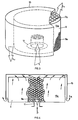
- FIG. 3 schematically shows a vapor condenser according to the invention, for example in a cylindrical design, as used in the arrangement according to FIG. 1.
- the granulate body 9 with granules 9a has the plug-in recess 11 described above for the connection.
- a protruding plug socket can be installed instead of a recess 11.
- the granulate body 9 is surrounded by the jacket 15, which is preferably made of metal.
- the exhaust air L penetrates through the connection at 11 into the granulate body 9, is distributed in the body, and finally exits at its free surface, as shown schematically at L 1 .
- Bottom and side surfaces of the granulate body 9 are preferably covered with a further casing 15a, optionally also made of metal, in order to force the exhaust air L to penetrate to the body surface 9b opposite the connection 11 and only to flow out there.
- the exhaust air flows, as shown in L 2 , to the outlet openings or the outlet slot 19 according to FIGS. 1 and 2.
- the circulation of the exhaust air is also shown in FIG Fig. 4 clearly visible.
- Um in the preferred embodiment without exhaust fan, ensure the air flow through the grease filter and vapor condenser, the control door of the Baking oven designed so that in the closed state only negligible air flow from the door joints into the Environment is possible.
- the vapor condenser according to the invention can not only be used Ovens are used, but also in the exhaust air duct over hobs. Depending on what is available Space can, according to FIGS. 1 and 2, the shape of the vapor condenser 9, 15 can be varied as desired.
Landscapes
- Engineering & Computer Science (AREA)
- Chemical & Material Sciences (AREA)
- Combustion & Propulsion (AREA)
- Mechanical Engineering (AREA)
- General Engineering & Computer Science (AREA)
- Baking, Grill, Roasting (AREA)
- Electric Ovens (AREA)
- General Preparation And Processing Of Foods (AREA)
Description
- Fig. 1
- schematisch, an einem erfindungsgemässen Backrohr, beispielsweise mit darüber aufgebautem Kochfeld, eine erste bevorzugte Ausführungsvariante eines erfindungsgemässen Wrasenkondensators;
- Fig. 2
- an einer Darstellung analog zu derjenigen von Fig. 1, eine weitere bevorzugte Ausführungsvariante eines erfindungsgemässen Wrasenkondensators, an einem erfindungsgemäss ausgestatteten Backrohr vorgesehen;
- Fig. 3
- schematisch, einen erfindungsgemässen Wrasenkondensator in der schematisch in Fig. 1 dargestellten Ausführungsform;
- Fig. 4
- schematisch, eine teilgeschnittene Darstellung des Kondensators nach Fig. 3 mit erfindungsgemäss eingesetztem Granulat zur weiteren Erläuterung seiner Funktionsweise.
Claims (22)
- Verfahren zur Reinigung von Koch- oder Backabluft, bei dem die Abluft durch ein Bett (9) eines porösen Materials getrieben wird, dadurch gekennzeichnet, dass die Abluft durch ein Bett eines saugfähigen, hydrophilen Granulates (9a) getrieben wird.
- Verfahren nach Anspruch 1, dadurch gekennzeichnet, dass das Bett mindestens als Teil eines Wärmespeichers (9, 15) eingesetzt wird.
- Verfahren nach einem der Ansprüche 1 oder 2, dadurch gekennzeichnet, dass die Abluft, grossräumig verteilt, nach dem Bett in die Umgebung ausgelassen wird.
- Verfahren nach einem der Ansprüche 1 bis 3, dadurch gekennzeichnet, dass die Abluft passiv, ohne Abluftgebläse, druckdifferenzgetrieben (p1) durchs Bett (9) gefördert wird.
- Verfahren nach Anspruch 2, dadurch gekennzeichnet, dass der Wärmespeicher in einem ohnehin beheizten Bereich angeordnet wird.
- Verfahren nach einem der Ansprüche 1 bis 5, dadurch gekennzeichnet, dass die Abluft durch ein Bett mit Blähtongranulat getrieben wird.
- Verfahren nach einem der Ansprüche 1 bis 6, dadurch gekennzeichnet, dass vor dem Bett eine Fettfilterung (5) vorgenommen wird, z.B. mittels eines Metall-Pressspanfilters.
- Backrohr, bei dem ein Bett (9) eines porösen Materials in einem Entlüftungspfad für Abluft zwischen Backraum (1) und Umgebung vorgesehen ist, dadurch gekennzeichnet, dass das Bett ein saugfähiges, hydrophiles Granulat (9a) enthält.
- Backrohr nach Anspruch 8, dadurch gekennzeichnet, dass das Bett (9) mindestens Teil eines Wärmespeichers (9, 15) ist, der vorzugsweise in einem ohnehin zu beheizenden Bereich (7) angeordnet ist, wie im Bereiche eines über dem Backrohr angeordneten Kochfeldes (21).
- Backrohr nach einem der Ansprüche 8 oder 9, dadurch gekennzeichnet, dass, verteilt, in die Umgebung ausmündende Abluftauslässe stromab des Bettes vorgesehen sind, diese vorzugsweise, bei über dem Backrohr angeordnetem Kochfeld (21), durch ohnehin an letzterem vorgesehene Spalten und Ritzen realisiert sind.
- Backrohr nach einem der Ansprüche 8 bis 10, dadurch gekennzeichnet, dass kein Abluftgebläse vorgesehen ist und die Abluftförderung durch Druckdifferenz (p1, pu) zwischen Backraum und Umgebung erfolgt.
- Backrohr nach einem der Ansprüche 8 bis 11, dadurch gekennzeichnet, dass dem Bett ein Fettfilter (5), z.B. aus Metallpressspänen, vorgeschaltet ist.
- Backrohr nach einem der Ansprüche 8 bis 12, dadurch gekennzeichnet, dass das Granulat mindestens vornehmlich Blähton ist.
- Backrohr nach einem der Ansprüche 8 bis 13, dadurch gekennzeichnet, dass vorzugsweise an der Oberseite des Backraumes, vorzugsweise im wesentlichen zentral, eine Abluftaustrittsöffnung (3) vorgesehen ist, vorzugsweise über ein Fettfilter (5) in den Backraum (1) ausmündend, und dass die Austrittsöffnung (3) ins Bett (9) ausmündet, welches in einem mit der Umgebung kommunizierenden Hohlraum (7) angeordnet ist.
- Backrohr nach einem der Ansprüche 8 bis 14, dadurch gekennzeichnet, dass das Bett (9) eine Granulatpatrone ist, die mit Abstand von einem Mantel (15), vorzugsweise aus Metall, ummantelt ist, welch letzterer mindestens eine Oeffnung in die Umgebung mindestens mitdefiniert, und/oder die Granulatpatronen-Aussenfläche teilweise im wesentlichen luftdicht ausgebildet (15a) ist.
- Backrohr nach einem der Ansprüche 8 bis 15, dadurch gekennzeichnet, dass mindestens das Bett (9) als auswechselbare Wrasenkondensatorpatrone ausgebildet ist.
- Wrasenkondensator, dadurch gekennzeichnet, dass er einen Granulatkörper (9) aus porösem, saugfähigem, hydrophilem Granulat (9a) umfasst.
- Wrasenkondensator nach Anspruch 17, dadurch gekennzeichnet, dass auf Abstand vom Granulatkörper (9) eine Ummantelung, vorzugsweise eine Metallummantelung, vorgesehen ist und/oder ein Teil der Granulatkörper-Aussenfläche im wesentlichen luftdicht ausgebildet (15a) ist.
- Wrasenkondensator nach einem der Ansprüche 17 oder 18, dadurch gekennzeichnet, dass er zylinderförmig ist und ein Anschlussstutzen oder eine Anschlussbuchse (11) am Granulatkörper (9) zentrisch vorgesehen ist zum Aufstecken des Wrasenkondensators.
- Wrasenkondensator nach einem der Ansprüche 17 oder 18, dadurch gekennzeichnet, dass er im wesentlichen kubusförmig ausgebildet ist und im Bereiche einer Kubuskante ein Anschlussstutzen oder eine Anschlussbuchse (11) am Granulatkörper (9) vorgesehen ist.
- Verwendung von porösem, saugfähigem, hydrophilem Granulat für die Wrasenfilterung von Koch- oder Backabluft.
- Verwendung nach Anspruch 21, von Blähtongranulat.
Priority Applications (3)
| Application Number | Priority Date | Filing Date | Title |
|---|---|---|---|
| EP93111346A EP0634612B1 (de) | 1993-07-15 | 1993-07-15 | Verfahren zur Reinigung von Koch- oder Backabluft, Backrohr, Wrasenkondensator und Verwendung von Granulat als Wrasenkondensatormaterial |
| AT93111346T ATE183818T1 (de) | 1993-07-15 | 1993-07-15 | Verfahren zur reinigung von koch- oder backabluft, backrohr, wrasenkondensator und verwendung von granulat als wrasenkondensatormaterial |
| DE59309747T DE59309747D1 (de) | 1993-07-15 | 1993-07-15 | Verfahren zur Reinigung von Koch- oder Backabluft, Backrohr, Wrasenkondensator und Verwendung von Granulat als Wrasenkondensatormaterial |
Applications Claiming Priority (1)
| Application Number | Priority Date | Filing Date | Title |
|---|---|---|---|
| EP93111346A EP0634612B1 (de) | 1993-07-15 | 1993-07-15 | Verfahren zur Reinigung von Koch- oder Backabluft, Backrohr, Wrasenkondensator und Verwendung von Granulat als Wrasenkondensatormaterial |
Publications (2)
| Publication Number | Publication Date |
|---|---|
| EP0634612A1 EP0634612A1 (de) | 1995-01-18 |
| EP0634612B1 true EP0634612B1 (de) | 1999-08-25 |
Family
ID=8213078
Family Applications (1)
| Application Number | Title | Priority Date | Filing Date |
|---|---|---|---|
| EP93111346A Expired - Lifetime EP0634612B1 (de) | 1993-07-15 | 1993-07-15 | Verfahren zur Reinigung von Koch- oder Backabluft, Backrohr, Wrasenkondensator und Verwendung von Granulat als Wrasenkondensatormaterial |
Country Status (3)
| Country | Link |
|---|---|
| EP (1) | EP0634612B1 (de) |
| AT (1) | ATE183818T1 (de) |
| DE (1) | DE59309747D1 (de) |
Cited By (1)
| Publication number | Priority date | Publication date | Assignee | Title |
|---|---|---|---|---|
| DE102006043184B4 (de) | 2005-10-10 | 2019-07-25 | BSH Hausgeräte GmbH | Gargerät |
Families Citing this family (3)
| Publication number | Priority date | Publication date | Assignee | Title |
|---|---|---|---|---|
| DE9402193U1 (de) * | 1994-02-10 | 1994-03-31 | HOBA Technische Software GmbH, 74523 Schwäbisch Hall | Dampfkondensierer |
| EP2283729A1 (de) | 2009-08-13 | 2011-02-16 | Electrolux Home Products Corporation N.V. | Verarbeitungskammer, Vorrichtung für Haushalts- und Industriegeräte und Sorptionskartusche |
| EP4279821A1 (de) * | 2022-05-18 | 2023-11-22 | B/E Aerospace, Inc. | Filter für einen flugzeug-ofen |
Family Cites Families (3)
| Publication number | Priority date | Publication date | Assignee | Title |
|---|---|---|---|---|
| US3446941A (en) * | 1966-09-14 | 1969-05-27 | Whirlpool Co | Oven heating means |
| DE3346019C2 (de) * | 1983-12-20 | 1985-11-07 | Bosch-Siemens Hausgeraete Gmbh, 7000 Stuttgart | Backofen |
| DE3700567A1 (de) * | 1987-01-10 | 1988-07-21 | Bauknecht Hausgeraete | Kondensoreinrichtung fuer in einem backofen entstehende wrasen |
-
1993
- 1993-07-15 EP EP93111346A patent/EP0634612B1/de not_active Expired - Lifetime
- 1993-07-15 AT AT93111346T patent/ATE183818T1/de not_active IP Right Cessation
- 1993-07-15 DE DE59309747T patent/DE59309747D1/de not_active Expired - Fee Related
Cited By (1)
| Publication number | Priority date | Publication date | Assignee | Title |
|---|---|---|---|---|
| DE102006043184B4 (de) | 2005-10-10 | 2019-07-25 | BSH Hausgeräte GmbH | Gargerät |
Also Published As
| Publication number | Publication date |
|---|---|
| DE59309747D1 (de) | 1999-09-30 |
| EP0634612A1 (de) | 1995-01-18 |
| ATE183818T1 (de) | 1999-09-15 |
Similar Documents
| Publication | Publication Date | Title |
|---|---|---|
| EP2254422B1 (de) | Gargerät mit einer wrasenkondensiereinrichtung | |
| DE69917770T2 (de) | Verfahren zum trocknen eines beschichteten substrats | |
| DE2414573C2 (de) | Unterdecke zur Abschirmung tragender Decken von Räumen | |
| DE20117490U1 (de) | Luftabsaugvorrichtung für einen Arbeitsplatz | |
| EP3701192A1 (de) | Kombinationsgerät mit dunstabzugsvorrichtung und kochfeld | |
| DE102016113356A1 (de) | Dunstabzugsvorrichtung für eine Fritteuse sowie Gargerät in Form einer Fritteuse | |
| EP0634612B1 (de) | Verfahren zur Reinigung von Koch- oder Backabluft, Backrohr, Wrasenkondensator und Verwendung von Granulat als Wrasenkondensatormaterial | |
| EP3759397B1 (de) | Tischlüfter und verfahren zum reinigen eines tischlüfters | |
| EP0275127A2 (de) | Kondensoreinrichtung für in einem Backofen entstehende Wrasen | |
| EP1340021A1 (de) | Backofen | |
| DE3219912A1 (de) | Vorrichtung zum kondensieren von kochdaempfen | |
| EP2677872B1 (de) | Verfahren zur entfernung von in schwaden enthaltenen organischen inhaltsstoffen und deren umwandlungsprodukten und zur wärmerückgewinnung aus schwaden und eine vorrichtung zur durchführung dieses verfahrens | |
| DE20205642U1 (de) | Dunstabsaugvorrichtung, insbesondere Dunstabzugshaube | |
| EP0730838A1 (de) | Fritiergerät | |
| DE2653323A1 (de) | Anordnung zum verhindern der staub- und dampfemission beim herstellen von koks und verwendung dieser anordnung | |
| DE2919761C2 (de) | Luftreinigungsgerät | |
| EP1094278A2 (de) | Dunstabzugsvorrichtung | |
| DE2229991C3 (de) | Dampfdruckkocher | |
| DE3643299C1 (en) | Apparatus for dehumidifying the interior exhaust air or exhaust gases and/or for condensing the vapour and waste steam from bakeries or the like | |
| DE3914198C2 (de) | Nachbrennkammer | |
| DE4321530A1 (de) | Luftführungsgerät | |
| DE4100859C2 (de) | ||
| DE8303643U1 (de) | Nischenluefter | |
| CH656942A5 (en) | Baking oven | |
| DE102005034303A1 (de) | Garofen |
Legal Events
| Date | Code | Title | Description |
|---|---|---|---|
| PUAI | Public reference made under article 153(3) epc to a published international application that has entered the european phase |
Free format text: ORIGINAL CODE: 0009012 |
|
| AK | Designated contracting states |
Kind code of ref document: A1 Designated state(s): AT CH DE DK ES FR GB IT LI SE |
|
| 17P | Request for examination filed |
Effective date: 19950703 |
|
| 17Q | First examination report despatched |
Effective date: 19970605 |
|
| GRAG | Despatch of communication of intention to grant |
Free format text: ORIGINAL CODE: EPIDOS AGRA |
|
| GRAG | Despatch of communication of intention to grant |
Free format text: ORIGINAL CODE: EPIDOS AGRA |
|
| GRAH | Despatch of communication of intention to grant a patent |
Free format text: ORIGINAL CODE: EPIDOS IGRA |
|
| GRAH | Despatch of communication of intention to grant a patent |
Free format text: ORIGINAL CODE: EPIDOS IGRA |
|
| GRAA | (expected) grant |
Free format text: ORIGINAL CODE: 0009210 |
|
| AK | Designated contracting states |
Kind code of ref document: B1 Designated state(s): AT CH DE DK ES FR GB IT LI SE |
|
| PG25 | Lapsed in a contracting state [announced via postgrant information from national office to epo] |
Ref country code: ES Free format text: THE PATENT HAS BEEN ANNULLED BY A DECISION OF A NATIONAL AUTHORITY Effective date: 19990825 |
|
| REF | Corresponds to: |
Ref document number: 183818 Country of ref document: AT Date of ref document: 19990915 Kind code of ref document: T |
|
| REG | Reference to a national code |
Ref country code: CH Ref legal event code: NV Representative=s name: TROESCH SCHEIDEGGER WERNER AG Ref country code: CH Ref legal event code: EP |
|
| REF | Corresponds to: |
Ref document number: 59309747 Country of ref document: DE Date of ref document: 19990930 |
|
| ITF | It: translation for a ep patent filed | ||
| PG25 | Lapsed in a contracting state [announced via postgrant information from national office to epo] |
Ref country code: DK Free format text: LAPSE BECAUSE OF FAILURE TO SUBMIT A TRANSLATION OF THE DESCRIPTION OR TO PAY THE FEE WITHIN THE PRESCRIBED TIME-LIMIT Effective date: 19991125 |
|
| ET | Fr: translation filed | ||
| GBT | Gb: translation of ep patent filed (gb section 77(6)(a)/1977) |
Effective date: 19991125 |
|
| PLBE | No opposition filed within time limit |
Free format text: ORIGINAL CODE: 0009261 |
|
| STAA | Information on the status of an ep patent application or granted ep patent |
Free format text: STATUS: NO OPPOSITION FILED WITHIN TIME LIMIT |
|
| PG25 | Lapsed in a contracting state [announced via postgrant information from national office to epo] |
Ref country code: GB Free format text: LAPSE BECAUSE OF NON-PAYMENT OF DUE FEES Effective date: 20000715 Ref country code: AT Free format text: LAPSE BECAUSE OF NON-PAYMENT OF DUE FEES Effective date: 20000715 |
|
| PG25 | Lapsed in a contracting state [announced via postgrant information from national office to epo] |
Ref country code: SE Free format text: LAPSE BECAUSE OF NON-PAYMENT OF DUE FEES Effective date: 20000716 |
|
| PG25 | Lapsed in a contracting state [announced via postgrant information from national office to epo] |
Ref country code: LI Free format text: LAPSE BECAUSE OF NON-PAYMENT OF DUE FEES Effective date: 20000731 Ref country code: CH Free format text: LAPSE BECAUSE OF NON-PAYMENT OF DUE FEES Effective date: 20000731 |
|
| 26N | No opposition filed | ||
| GBPC | Gb: european patent ceased through non-payment of renewal fee |
Effective date: 20000715 |
|
| REG | Reference to a national code |
Ref country code: CH Ref legal event code: PL |
|
| EUG | Se: european patent has lapsed |
Ref document number: 93111346.8 |
|
| PG25 | Lapsed in a contracting state [announced via postgrant information from national office to epo] |
Ref country code: DE Free format text: LAPSE BECAUSE OF NON-PAYMENT OF DUE FEES Effective date: 20010501 |
|
| PG25 | Lapsed in a contracting state [announced via postgrant information from national office to epo] |
Ref country code: FR Free format text: LAPSE BECAUSE OF NON-PAYMENT OF DUE FEES Effective date: 20010928 |
|
| REG | Reference to a national code |
Ref country code: FR Ref legal event code: ST |
|
| PG25 | Lapsed in a contracting state [announced via postgrant information from national office to epo] |
Ref country code: IT Free format text: LAPSE BECAUSE OF NON-PAYMENT OF DUE FEES;WARNING: LAPSES OF ITALIAN PATENTS WITH EFFECTIVE DATE BEFORE 2007 MAY HAVE OCCURRED AT ANY TIME BEFORE 2007. THE CORRECT EFFECTIVE DATE MAY BE DIFFERENT FROM THE ONE RECORDED. Effective date: 20050715 |
|
| PG25 | Lapsed in a contracting state [announced via postgrant information from national office to epo] |
Ref country code: FR Free format text: LAPSE BECAUSE OF NON-PAYMENT OF DUE FEES Effective date: 20000731 |