EP0634276B1 - Appareil pour couper des bandes - Google Patents
Appareil pour couper des bandes Download PDFInfo
- Publication number
- EP0634276B1 EP0634276B1 EP94304283A EP94304283A EP0634276B1 EP 0634276 B1 EP0634276 B1 EP 0634276B1 EP 94304283 A EP94304283 A EP 94304283A EP 94304283 A EP94304283 A EP 94304283A EP 0634276 B1 EP0634276 B1 EP 0634276B1
- Authority
- EP
- European Patent Office
- Prior art keywords
- tape
- image receiving
- cut edge
- layer
- wall
- Prior art date
- Legal status (The legal status is an assumption and is not a legal conclusion. Google has not performed a legal analysis and makes no representation as to the accuracy of the status listed.)
- Expired - Lifetime
Links
- 238000007639 printing Methods 0.000 claims description 12
- 239000000853 adhesive Substances 0.000 claims description 10
- 230000001070 adhesive effect Effects 0.000 claims description 10
- 239000010410 layer Substances 0.000 description 43
- 238000007651 thermal printing Methods 0.000 description 6
- 229920000728 polyester Polymers 0.000 description 5
- 239000012790 adhesive layer Substances 0.000 description 4
- 239000000463 material Substances 0.000 description 4
- 238000000034 method Methods 0.000 description 3
- 229920003023 plastic Polymers 0.000 description 3
- 239000004033 plastic Substances 0.000 description 3
- 238000000926 separation method Methods 0.000 description 3
- 238000013459 approach Methods 0.000 description 2
- 238000010276 construction Methods 0.000 description 2
- 230000000694 effects Effects 0.000 description 1
- 210000004905 finger nail Anatomy 0.000 description 1
- 238000010438 heat treatment Methods 0.000 description 1
- 239000012858 resilient material Substances 0.000 description 1
- 230000000717 retained effect Effects 0.000 description 1
- 238000010008 shearing Methods 0.000 description 1
Images

Classifications
-
- B—PERFORMING OPERATIONS; TRANSPORTING
- B41—PRINTING; LINING MACHINES; TYPEWRITERS; STAMPS
- B41J—TYPEWRITERS; SELECTIVE PRINTING MECHANISMS, i.e. MECHANISMS PRINTING OTHERWISE THAN FROM A FORME; CORRECTION OF TYPOGRAPHICAL ERRORS
- B41J3/00—Typewriters or selective printing or marking mechanisms characterised by the purpose for which they are constructed
- B41J3/407—Typewriters or selective printing or marking mechanisms characterised by the purpose for which they are constructed for marking on special material
- B41J3/4075—Tape printers; Label printers
-
- B—PERFORMING OPERATIONS; TRANSPORTING
- B41—PRINTING; LINING MACHINES; TYPEWRITERS; STAMPS
- B41J—TYPEWRITERS; SELECTIVE PRINTING MECHANISMS, i.e. MECHANISMS PRINTING OTHERWISE THAN FROM A FORME; CORRECTION OF TYPOGRAPHICAL ERRORS
- B41J11/00—Devices or arrangements of selective printing mechanisms, e.g. ink-jet printers or thermal printers, for supporting or handling copy material in sheet or web form
- B41J11/66—Applications of cutting devices
- B41J11/70—Applications of cutting devices cutting perpendicular to the direction of paper feed
- B41J11/703—Cutting of tape
-
- Y—GENERAL TAGGING OF NEW TECHNOLOGICAL DEVELOPMENTS; GENERAL TAGGING OF CROSS-SECTIONAL TECHNOLOGIES SPANNING OVER SEVERAL SECTIONS OF THE IPC; TECHNICAL SUBJECTS COVERED BY FORMER USPC CROSS-REFERENCE ART COLLECTIONS [XRACs] AND DIGESTS
- Y10—TECHNICAL SUBJECTS COVERED BY FORMER USPC
- Y10T—TECHNICAL SUBJECTS COVERED BY FORMER US CLASSIFICATION
- Y10T156/00—Adhesive bonding and miscellaneous chemical manufacture
- Y10T156/11—Methods of delaminating, per se; i.e., separating at bonding face
- Y10T156/1168—Gripping and pulling work apart during delaminating
-
- Y—GENERAL TAGGING OF NEW TECHNOLOGICAL DEVELOPMENTS; GENERAL TAGGING OF CROSS-SECTIONAL TECHNOLOGIES SPANNING OVER SEVERAL SECTIONS OF THE IPC; TECHNICAL SUBJECTS COVERED BY FORMER USPC CROSS-REFERENCE ART COLLECTIONS [XRACs] AND DIGESTS
- Y10—TECHNICAL SUBJECTS COVERED BY FORMER USPC
- Y10T—TECHNICAL SUBJECTS COVERED BY FORMER US CLASSIFICATION
- Y10T156/00—Adhesive bonding and miscellaneous chemical manufacture
- Y10T156/19—Delaminating means
- Y10T156/1978—Delaminating bending means
- Y10T156/1983—Poking delaminating means
-
- Y—GENERAL TAGGING OF NEW TECHNOLOGICAL DEVELOPMENTS; GENERAL TAGGING OF CROSS-SECTIONAL TECHNOLOGIES SPANNING OVER SEVERAL SECTIONS OF THE IPC; TECHNICAL SUBJECTS COVERED BY FORMER USPC CROSS-REFERENCE ART COLLECTIONS [XRACs] AND DIGESTS
- Y10—TECHNICAL SUBJECTS COVERED BY FORMER USPC
- Y10T—TECHNICAL SUBJECTS COVERED BY FORMER US CLASSIFICATION
- Y10T83/00—Cutting
- Y10T83/343—With means to deform work temporarily
-
- Y—GENERAL TAGGING OF NEW TECHNOLOGICAL DEVELOPMENTS; GENERAL TAGGING OF CROSS-SECTIONAL TECHNOLOGIES SPANNING OVER SEVERAL SECTIONS OF THE IPC; TECHNICAL SUBJECTS COVERED BY FORMER USPC CROSS-REFERENCE ART COLLECTIONS [XRACs] AND DIGESTS
- Y10—TECHNICAL SUBJECTS COVERED BY FORMER USPC
- Y10T—TECHNICAL SUBJECTS COVERED BY FORMER US CLASSIFICATION
- Y10T83/00—Cutting
- Y10T83/929—Tool or tool with support
- Y10T83/9309—Anvil
-
- Y—GENERAL TAGGING OF NEW TECHNOLOGICAL DEVELOPMENTS; GENERAL TAGGING OF CROSS-SECTIONAL TECHNOLOGIES SPANNING OVER SEVERAL SECTIONS OF THE IPC; TECHNICAL SUBJECTS COVERED BY FORMER USPC CROSS-REFERENCE ART COLLECTIONS [XRACs] AND DIGESTS
- Y10—TECHNICAL SUBJECTS COVERED BY FORMER USPC
- Y10T—TECHNICAL SUBJECTS COVERED BY FORMER US CLASSIFICATION
- Y10T83/00—Cutting
- Y10T83/929—Tool or tool with support
- Y10T83/9411—Cutting couple type
- Y10T83/9447—Shear type
-
- Y—GENERAL TAGGING OF NEW TECHNOLOGICAL DEVELOPMENTS; GENERAL TAGGING OF CROSS-SECTIONAL TECHNOLOGIES SPANNING OVER SEVERAL SECTIONS OF THE IPC; TECHNICAL SUBJECTS COVERED BY FORMER USPC CROSS-REFERENCE ART COLLECTIONS [XRACs] AND DIGESTS
- Y10—TECHNICAL SUBJECTS COVERED BY FORMER USPC
- Y10T—TECHNICAL SUBJECTS COVERED BY FORMER US CLASSIFICATION
- Y10T83/00—Cutting
- Y10T83/929—Tool or tool with support
- Y10T83/9493—Stationary cutter
- Y10T83/9498—Parallel cutting edges
Definitions
- the present invention relates to tape cutting apparatus and is particularly but not exclusively concerned with cutting tape used in thermal printing devices.
- Thermal printing devices of the type with which the present invention is primarily concerned operate with a supply of tape arranged to receive an image and a means for transferring image onto the tape.
- a tape holding case holds a supply of image receiving tape and a supply of an image transfer ribbon, the image receiving tape and the transfer ribbon being passed in overlap through a printing zone of the printing device.
- a printing device operating with a tape holding case of this type is described for example in EP-A-0267890 (Varitronics, Inc.).
- Other printing devices have been made in which letters are transferred to an image receiving tape by a dry lettering or dry film impression process. In all of these printing devices, the construction of the image receiving tape is substantially the same.
- it comprises an upper layer for receiving an image which is secured to a releaseable backing layer by a layer of adhesive.
- an image or message has been printed on the tape, it is desired to cut off that portion of the tape to enable it to be used as a label.
- it is difficult to remove the releaseable backing layer from the upper layer it is necessary first to separate the closely adhered end portions of the releaseable backing layer and the upper layer, for example using a fingernail or tweezers so that the separated end portion of the releaseable backing layer can be finger gripped to peel it off the adhesive layer. This is a relatively difficult procedure and furthermore can result in the ends of the label being damaged in the process.
- EP-0526213 which provides a different solution to the problem of enabling the releaseable backing sheet to be removed easily by providing a cutting system which causes the end portions of the tape to separate as a result of forming a bend in the tape before cutting.
- the principle of forming a bend in the tape relies upon the difference in resilience between the image receiving tape and the backing sheet. If the backing sheet lies on the inner radius of the bend, the natural resilience of the image receiving tape will cause it to lift at the cut edge and to separate from the backing sheet against the strength of the adhesive layer. However, it can be difficult to bend the tape reliably around an appropriate radius to achieve a consistent result in separation at the cut edge of a tape.
- an apparatus for separating an upper layer from a lower layer against an adhesive strength between the upper and lower layers at a cut edge of a portion of tape comprising a tape separating member at which a bend can be formed in the tape and which has a recess having a foremost wall and rearmost wall in the direction of withdrawal of the tape, characterised in that the rearmost wall provides a wall portion configured to prevent the cut edge of the tape from slipping upwards allowing the tape to straighten so that as the tape is drawn out of the tape separating member to straighten it the resilience in the upper layer overcomes the adhesive strength between upper and lower layers and causes them to separate at the cut edge of the tape.
- the wall portion includes a notch which serves to retain the cut edge of the tape as the tape is drawn out.
- a slide member cooperates with the tape separating member to cause a bend in said tape.
- the slide member can be attached to a cutting blade which cuts the tape to form said cut edge before the bend if formed.
- a tape holding case containing a supply of image receiving tape having an upper layer secured to a lower layer by adhesive may also contain such apparatus for separating the layers at a cut edge.
- a movable arm or slide pushes the freshly cut end of a label into a recess.
- the arm or slide is then retracted.
- the deformed end of the label is retained in the recess (provided the latter is sufficiently deep) by friction between the label and the walls of the recess.
- the cut edge of the label can preferably be trapped in a notch which prevents it from slipping upwards out of the recess.
- the paper layer being less elastic, remains trapped momentarily longer than the plastic layer, so that full separation occurs between the layers over a distance slightly greater than the width of the recess.
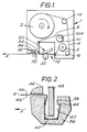
- reference numeral 1 designates a tape holding case or cassette.
- the tape holding case contains a supply spool 2 of an image receiving tape 4.
- the image receiving tape comprises an upper layer 4a ( Figure 2) which receives a printed image.
- the upper layer can for example be polyester or paper, and is generally a thin resilient material.
- the underside of the upper layer is coated with an adhesive layer to which is secured a releaseable backing layer 4b ( Figure 2).
- the construction of the image receiving tape 4 is described in more detail hereinafter with reference to the tape cutting apparatus.
- the cassette 1 also houses an image transfer ribbon 6.
- the ribbon 6 extends from a supply spool 8 to a take-up spool 10.
- the take-up spool 10 is driven as indicated by arrow 10A in a direction to cause the ribbon 6 to be fed from the supply spool 8 to the take-up spool 10 via a print zone generally designated 12.
- the image receiving tape 4 is also guided through the print zone 12 overlapped with the transfer ribbon 6.
- Reference numerals 14 and 16 denote guide posts for guiding the image receiving tape 4 through the cassette 1.
- the cassette 1 is intended to cooperate with a thermal printing device.
- the printing device carries a print head 20 and a platen 22.
- the print head is movable between an operative position shown in Figure 1 in which it is in contact with the platen 22 and in which the image receiving tape and transfer ribbon are pinched in overlap between the print head and the platen and an inoperative position in which the tapes are released to enable the cassette to be removed.
- an image is transferred to the image receiving tape as a result of selectively heating pixels on the thermal print head.
- thermal printing devices are known, one example being illustrated in EP-A-0267890.
- the platen 22 is rotatable to draw the image receiving tape once printed past the print zone and out of the cassette 1. Once a message has been printed, the image receiving tape is fed to a cutting apparatus 26, which may or may not be integral with the cassette.
- the cutting apparatus 26 includes a cutter support member carrying a blade 30 which acts against an anvil 32 to cut off the printed portion of the tape.
- the cutting apparatus 26 also includes a tape separating apparatus 34.
- the tape separating apparatus 34 comprises a tape separating member 36 which is indicated in section in Figure 2 and in which is defined a recess 38 having foremost and rearmost walls 40,42. The directions foremost and rearmost are taken in the direction of withdrawal of the tape from the apparatus. This direction is denoted by arrow A in Figure 2.
- the tape 4 is shown in Figure 2 with its image receiving layer 4a on the lower side and the releaseable backing layer 4b on the upper side. There is formed in the rearmost wall 42 of the recess 38 a notch 44 which serves to trap the cut edge of the tape as will be described later.
- Reference numeral 46 denotes a guide wall for the tape as it is withdrawn from the tape separating apparatus 34 in the direction of arrow A.
- the tape separating apparatus includes a slide member 48 which is slidable into the recess 38.
- the slide member does not trap or fix the tape 4 but merely causes a bend to be formed in the tape 4 so that the tape is located in the recess 38, against the walls 40 and 42.
- the end of the tape is in contact with the wall over most of its length (see Figure 2).
- the tape separating member 36 can be formed as part of the cassette 1 or as part of the printing device itself. Alternatively, it can be a separate component altogether.
- the elastic forces in the image receiving layer arise as a result of the natural resilience of the material used for the image receiving layer, generally a plastics material.
Claims (6)
- Appareil (34) pour séparer une couche supérieure (4a) d'une couche inférieure (4b) contre la force d'un adhésif entre les couches supérieure et inférieure, à un bord coupé (50) d'un tronçon de bande (4), l'appareil comportant un élément (36) de séparation de bande auquel un coude peut être formé dans la bande (4) et qui présente un évidement (38) ayant une paroi (40) située le plus en avant et une paroi (42) située le plus en arrière dans le sens dans lequel la bande est tirée, caractérisé en ce que le paroi (42) située le plus en arrière présente une partie de paroi configurée pour empêcher le bord coupé de la bande de glisser vers le haut permettant à la bande (4) d'être redressée afin que, lorsque la bande 4 est tirée à l'extérieur de l'élément (36) de séparation de bande pour être redressée, l'élasticité présente dans la couche supérieure surmonte la force de l'adhésif entre les couches supérieure et inférieure et provoque leur séparation au niveau du bord coupé (50) de la bande (4).
- Appareil selon la revendication 1, dans lequel la partie de paroi présente une encoche (44) qui sert à retenir le bord coupé (50) de la bande (4) pendant que la bande est tirée vers l'extérieur.
- Appareil selon l'une quelconque des revendications précédentes, qui comporte un élément coulissant (48) conçu pour coopérer avec l'élément (36) de séparation de bande afin de provoquer la formation d'un coude dans ladite bande (4).
- Appareil selon la revendication 3, dans lequel l'élément coulissant (36) est relié à une lame de coupe (30) qui coupe la bande (4) pour former ledit bord coupé (50) avant que le coude soit formé.
- Boítier portant une bande, qui contient un appareil selon l'une quelconque des revendications précédentes et une provision de bandes (4) de réception d'images, ladite bande de réception d'images ayant une couche supérieure (4a) et une couche inférieure (4b) fixées l'une à l'autre par un adhésif.
- Dispositif d'impression, comportant :un mécanisme d'impression destiné à imprimer une image sur une bande (4) de réception d'images ;un organe de coupe (26) destiné à sectionner un tronçon de la bande de réception d'images ;ladite bande (4) de réception d'images ayant une couche supérieure (4a) et une couche inférieure (4b) fixée l'une à l'autre par un adhésif ; etun appareil selon l'une quelconque des revendications 1 à 5.
Applications Claiming Priority (2)
| Application Number | Priority Date | Filing Date | Title |
|---|---|---|---|
| GB939314389A GB9314389D0 (en) | 1993-07-12 | 1993-07-12 | Tape cutting apparatus |
| GB9314389 | 1993-07-12 |
Publications (3)
| Publication Number | Publication Date |
|---|---|
| EP0634276A2 EP0634276A2 (fr) | 1995-01-18 |
| EP0634276A3 EP0634276A3 (fr) | 1995-08-30 |
| EP0634276B1 true EP0634276B1 (fr) | 1998-01-28 |
Family
ID=10738680
Family Applications (1)
| Application Number | Title | Priority Date | Filing Date |
|---|---|---|---|
| EP94304283A Expired - Lifetime EP0634276B1 (fr) | 1993-07-12 | 1994-06-14 | Appareil pour couper des bandes |
Country Status (6)
| Country | Link |
|---|---|
| US (1) | US5569354A (fr) |
| EP (1) | EP0634276B1 (fr) |
| JP (1) | JP2714534B2 (fr) |
| AU (1) | AU677665B2 (fr) |
| DE (2) | DE634276T1 (fr) |
| GB (1) | GB9314389D0 (fr) |
Families Citing this family (6)
| Publication number | Priority date | Publication date | Assignee | Title |
|---|---|---|---|---|
| DE69522309T2 (de) * | 1994-12-21 | 2002-05-02 | King Jim Co Ltd | Verfahren und Vorrichtung zur Abtrennung eines Halterstreifens von einem Klebestreifen |
| DE69724190T2 (de) * | 1996-06-18 | 2004-02-26 | Dainippon Screen Mfg. Co., Ltd. | Bildaufzeichnungs- Vorrichtung und Verfahren |
| TW359660B (en) | 1996-11-07 | 1999-06-01 | Seiko Epson Corp | Peeling device, tape processing device incorporating the peeling device, and tape printing apparatus incorporating the tape processing device |
| DE19832093A1 (de) | 1997-08-22 | 1999-02-25 | Esselte Nv | Banddruckgerät |
| GB9808445D0 (en) | 1998-04-21 | 1998-06-17 | Esselte Nv | Tape printing device |
| US6277234B1 (en) * | 1999-06-01 | 2001-08-21 | Lucent Technologies, Inc. | Method and apparatus for removing work pieces adhered to a support |
Family Cites Families (7)
| Publication number | Priority date | Publication date | Assignee | Title |
|---|---|---|---|---|
| US3533616A (en) * | 1967-05-18 | 1970-10-13 | Minnesota Mining & Mfg | Tape severing and liner tabber |
| NL147693B (nl) * | 1970-09-30 | 1975-11-17 | Wavin Bv | Inrichting voor het van elkaar verwijderen van twee op elkaar liggende dunne lagen. |
| US4177104A (en) * | 1977-11-14 | 1979-12-04 | W. H. Brady Co. | Apparatus for separating laminated layers |
| GB2008028A (en) * | 1977-11-10 | 1979-05-31 | Brady Co W H | Separating laminated layers |
| JPS63250190A (ja) * | 1987-04-06 | 1988-10-18 | ソマ−ル株式会社 | 薄膜剥離用引起装置 |
| JPH0634126Y2 (ja) * | 1987-11-28 | 1994-09-07 | ブラザー工業株式会社 | 剥離紙付き印字テープ切断機構を備えた印字装置 |
| JP3611249B2 (ja) * | 1991-08-02 | 2005-01-19 | ブラザー工業株式会社 | 印刷装置 |
-
1993
- 1993-07-12 GB GB939314389A patent/GB9314389D0/en active Pending
-
1994
- 1994-06-14 DE DE0634276T patent/DE634276T1/de active Pending
- 1994-06-14 DE DE69408226T patent/DE69408226T2/de not_active Expired - Fee Related
- 1994-06-14 EP EP94304283A patent/EP0634276B1/fr not_active Expired - Lifetime
- 1994-06-27 US US08/266,817 patent/US5569354A/en not_active Expired - Fee Related
- 1994-07-07 AU AU67328/94A patent/AU677665B2/en not_active Ceased
- 1994-07-12 JP JP6160302A patent/JP2714534B2/ja not_active Expired - Fee Related
Also Published As
| Publication number | Publication date |
|---|---|
| JPH0753119A (ja) | 1995-02-28 |
| US5569354A (en) | 1996-10-29 |
| DE634276T1 (de) | 1995-10-12 |
| AU677665B2 (en) | 1997-05-01 |
| DE69408226T2 (de) | 1998-05-20 |
| GB9314389D0 (en) | 1993-08-25 |
| EP0634276A3 (fr) | 1995-08-30 |
| DE69408226D1 (de) | 1998-03-05 |
| JP2714534B2 (ja) | 1998-02-16 |
| AU6732894A (en) | 1995-01-19 |
| EP0634276A2 (fr) | 1995-01-18 |
Similar Documents
| Publication | Publication Date | Title |
|---|---|---|
| JP4133401B2 (ja) | テープ保持ケース及びそれを用いた印字装置 | |
| EP0834404B1 (fr) | Procédé et appareil pour l'impression et la manipulation d'étiquettes équipées ou dépourvues de bande support | |
| US6686016B2 (en) | Thermoplastic adhesive dispensing method and apparatus | |
| EP0634277B1 (fr) | Dispositif pour couper des bandes | |
| EP0758979B1 (fr) | Imprimante pour supports sans doublure et comportant un dos adhesif | |
| US5538591A (en) | Tape cutting apparatus | |
| US4189337A (en) | Real time labeler system | |
| US9611062B2 (en) | Method and device for application of a label to an object | |
| KR101547169B1 (ko) | 라벨링 장치 | |
| EP0634276B1 (fr) | Appareil pour couper des bandes | |
| EP0506257B1 (fr) | Méthode et appareil pour séparer une feuille support d'une étiquette auto-collante | |
| US4469550A (en) | Tool for setting up and applying pressure sensitive graphic materials | |
| JP3753460B2 (ja) | 台紙なしラベルの印字切断装置 | |
| EP1075423B1 (fr) | Separateur pour stratifie d'impression | |
| JP2005105170A (ja) | 折り畳みテープ及びテープカセット | |
| JP2006213886A (ja) | テープおよび当該テープを備えたテープカセット | |
| JP2920939B2 (ja) | テープ印刷装置 | |
| JP2904142B2 (ja) | レタリングペン | |
| JP2007111872A (ja) | チューブ及びテーププリンタのカッタ機構 |
Legal Events
| Date | Code | Title | Description |
|---|---|---|---|
| PUAI | Public reference made under article 153(3) epc to a published international application that has entered the european phase |
Free format text: ORIGINAL CODE: 0009012 |
|
| AK | Designated contracting states |
Kind code of ref document: A2 Designated state(s): DE FR GB IT |
|
| ITCL | It: translation for ep claims filed |
Representative=s name: BARZANO' E ZANARDO MILANO S.P.A. |
|
| EL | Fr: translation of claims filed | ||
| PUAL | Search report despatched |
Free format text: ORIGINAL CODE: 0009013 |
|
| AK | Designated contracting states |
Kind code of ref document: A3 Designated state(s): DE FR GB IT |
|
| DET | De: translation of patent claims | ||
| 17P | Request for examination filed |
Effective date: 19951014 |
|
| RAP1 | Party data changed (applicant data changed or rights of an application transferred) |
Owner name: ESSELTE N.V. |
|
| 17Q | First examination report despatched |
Effective date: 19961014 |
|
| GRAG | Despatch of communication of intention to grant |
Free format text: ORIGINAL CODE: EPIDOS AGRA |
|
| GRAG | Despatch of communication of intention to grant |
Free format text: ORIGINAL CODE: EPIDOS AGRA |
|
| GRAH | Despatch of communication of intention to grant a patent |
Free format text: ORIGINAL CODE: EPIDOS IGRA |
|
| GRAH | Despatch of communication of intention to grant a patent |
Free format text: ORIGINAL CODE: EPIDOS IGRA |
|
| GRAA | (expected) grant |
Free format text: ORIGINAL CODE: 0009210 |
|
| AK | Designated contracting states |
Kind code of ref document: B1 Designated state(s): DE FR GB IT |
|
| PG25 | Lapsed in a contracting state [announced via postgrant information from national office to epo] |
Ref country code: IT Free format text: LAPSE BECAUSE OF FAILURE TO SUBMIT A TRANSLATION OF THE DESCRIPTION OR TO PAY THE FEE WITHIN THE PRESCRIBED TIME-LIMIT;WARNING: LAPSES OF ITALIAN PATENTS WITH EFFECTIVE DATE BEFORE 2007 MAY HAVE OCCURRED AT ANY TIME BEFORE 2007. THE CORRECT EFFECTIVE DATE MAY BE DIFFERENT FROM THE ONE RECORDED. Effective date: 19980128 |
|
| REF | Corresponds to: |
Ref document number: 69408226 Country of ref document: DE Date of ref document: 19980305 |
|
| ET | Fr: translation filed | ||
| PLBE | No opposition filed within time limit |
Free format text: ORIGINAL CODE: 0009261 |
|
| STAA | Information on the status of an ep patent application or granted ep patent |
Free format text: STATUS: NO OPPOSITION FILED WITHIN TIME LIMIT |
|
| 26N | No opposition filed | ||
| REG | Reference to a national code |
Ref country code: GB Ref legal event code: IF02 |
|
| PGFP | Annual fee paid to national office [announced via postgrant information from national office to epo] |
Ref country code: FR Payment date: 20020610 Year of fee payment: 9 |
|
| PGFP | Annual fee paid to national office [announced via postgrant information from national office to epo] |
Ref country code: GB Payment date: 20020612 Year of fee payment: 9 |
|
| PGFP | Annual fee paid to national office [announced via postgrant information from national office to epo] |
Ref country code: DE Payment date: 20020619 Year of fee payment: 9 |
|
| PG25 | Lapsed in a contracting state [announced via postgrant information from national office to epo] |
Ref country code: GB Free format text: LAPSE BECAUSE OF NON-PAYMENT OF DUE FEES Effective date: 20030614 |
|
| PG25 | Lapsed in a contracting state [announced via postgrant information from national office to epo] |
Ref country code: DE Free format text: LAPSE BECAUSE OF NON-PAYMENT OF DUE FEES Effective date: 20040101 |
|
| GBPC | Gb: european patent ceased through non-payment of renewal fee |
Effective date: 20030614 |
|
| PG25 | Lapsed in a contracting state [announced via postgrant information from national office to epo] |
Ref country code: FR Free format text: LAPSE BECAUSE OF NON-PAYMENT OF DUE FEES Effective date: 20040227 |
|
| REG | Reference to a national code |
Ref country code: FR Ref legal event code: ST |