EP0633994B1 - Temperaturregelung - Google Patents
Temperaturregelung Download PDFInfo
- Publication number
- EP0633994B1 EP0633994B1 EP93906725A EP93906725A EP0633994B1 EP 0633994 B1 EP0633994 B1 EP 0633994B1 EP 93906725 A EP93906725 A EP 93906725A EP 93906725 A EP93906725 A EP 93906725A EP 0633994 B1 EP0633994 B1 EP 0633994B1
- Authority
- EP
- European Patent Office
- Prior art keywords
- panels
- panel
- fluid medium
- ceiling
- room
- Prior art date
- Legal status (The legal status is an assumption and is not a legal conclusion. Google has not performed a legal analysis and makes no representation as to the accuracy of the status listed.)
- Expired - Lifetime
Links
- 239000012530 fluid Substances 0.000 claims description 22
- 239000000463 material Substances 0.000 claims description 14
- 238000001816 cooling Methods 0.000 claims description 10
- 239000004033 plastic Substances 0.000 claims description 10
- 229920003023 plastic Polymers 0.000 claims description 10
- 238000009833 condensation Methods 0.000 claims description 7
- 230000005494 condensation Effects 0.000 claims description 7
- 239000003973 paint Substances 0.000 claims description 7
- 238000000034 method Methods 0.000 claims description 6
- XLYOFNOQVPJJNP-UHFFFAOYSA-N water Substances O XLYOFNOQVPJJNP-UHFFFAOYSA-N 0.000 abstract description 17
- 238000010438 heat treatment Methods 0.000 description 3
- PPBRXRYQALVLMV-UHFFFAOYSA-N Styrene Chemical compound C=CC1=CC=CC=C1 PPBRXRYQALVLMV-UHFFFAOYSA-N 0.000 description 2
- 241000894006 Bacteria Species 0.000 description 1
- 229920000742 Cotton Polymers 0.000 description 1
- 229920007962 Styrene Methyl Methacrylate Polymers 0.000 description 1
- 239000000654 additive Substances 0.000 description 1
- 239000007798 antifreeze agent Substances 0.000 description 1
- 230000015572 biosynthetic process Effects 0.000 description 1
- 229920002678 cellulose Polymers 0.000 description 1
- 239000001913 cellulose Substances 0.000 description 1
- 239000003795 chemical substances by application Substances 0.000 description 1
- 239000002131 composite material Substances 0.000 description 1
- 239000002826 coolant Substances 0.000 description 1
- 239000000975 dye Substances 0.000 description 1
- 238000000605 extraction Methods 0.000 description 1
- 239000004744 fabric Substances 0.000 description 1
- 238000009434 installation Methods 0.000 description 1
- 239000012528 membrane Substances 0.000 description 1
- 239000002184 metal Substances 0.000 description 1
- 229920003229 poly(methyl methacrylate) Polymers 0.000 description 1
- 239000004417 polycarbonate Substances 0.000 description 1
- 229920000515 polycarbonate Polymers 0.000 description 1
- 239000004926 polymethyl methacrylate Substances 0.000 description 1
- 230000005855 radiation Effects 0.000 description 1
Images
Classifications
-
- F—MECHANICAL ENGINEERING; LIGHTING; HEATING; WEAPONS; BLASTING
- F24—HEATING; RANGES; VENTILATING
- F24D—DOMESTIC- OR SPACE-HEATING SYSTEMS, e.g. CENTRAL HEATING SYSTEMS; DOMESTIC HOT-WATER SUPPLY SYSTEMS; ELEMENTS OR COMPONENTS THEREFOR
- F24D3/00—Hot-water central heating systems
- F24D3/12—Tube and panel arrangements for ceiling, wall, or underfloor heating
- F24D3/16—Tube and panel arrangements for ceiling, wall, or underfloor heating mounted on, or adjacent to, a ceiling, wall or floor
- F24D3/165—Suspended radiant heating ceiling
-
- F—MECHANICAL ENGINEERING; LIGHTING; HEATING; WEAPONS; BLASTING
- F24—HEATING; RANGES; VENTILATING
- F24F—AIR-CONDITIONING; AIR-HUMIDIFICATION; VENTILATION; USE OF AIR CURRENTS FOR SCREENING
- F24F5/00—Air-conditioning systems or apparatus not covered by F24F1/00 or F24F3/00, e.g. using solar heat or combined with household units such as an oven or water heater
- F24F5/0089—Systems using radiation from walls or panels
-
- Y—GENERAL TAGGING OF NEW TECHNOLOGICAL DEVELOPMENTS; GENERAL TAGGING OF CROSS-SECTIONAL TECHNOLOGIES SPANNING OVER SEVERAL SECTIONS OF THE IPC; TECHNICAL SUBJECTS COVERED BY FORMER USPC CROSS-REFERENCE ART COLLECTIONS [XRACs] AND DIGESTS
- Y02—TECHNOLOGIES OR APPLICATIONS FOR MITIGATION OR ADAPTATION AGAINST CLIMATE CHANGE
- Y02B—CLIMATE CHANGE MITIGATION TECHNOLOGIES RELATED TO BUILDINGS, e.g. HOUSING, HOUSE APPLIANCES OR RELATED END-USER APPLICATIONS
- Y02B30/00—Energy efficient heating, ventilation or air conditioning [HVAC]
-
- Y—GENERAL TAGGING OF NEW TECHNOLOGICAL DEVELOPMENTS; GENERAL TAGGING OF CROSS-SECTIONAL TECHNOLOGIES SPANNING OVER SEVERAL SECTIONS OF THE IPC; TECHNICAL SUBJECTS COVERED BY FORMER USPC CROSS-REFERENCE ART COLLECTIONS [XRACs] AND DIGESTS
- Y10—TECHNICAL SUBJECTS COVERED BY FORMER USPC
- Y10S—TECHNICAL SUBJECTS COVERED BY FORMER USPC CROSS-REFERENCE ART COLLECTIONS [XRACs] AND DIGESTS
- Y10S62/00—Refrigeration
- Y10S62/01—Radiant cooling
Definitions
- the invention relates to the temperature control of areas in buildings such as rooms in offices, hotels, retail shops, supermarkets, hospitals, and the like, by the cooling of rooms by transfer of heat from the air in the room by means of ceiling structure suspended below the top surface of the room.
- GB-A-778317 discloses a heating panel formed of plastics and directly exposed to a room, the panel having canals through which flows a heating medium. The panels are attached by hooks to a ceiling. The panels may be corrugated or ribbed or otherwise shaped.
- GB-A-1497261 discloses a cooling panel comprising a composite panel through which cooling medium can flow. A sheet or membrane of material impervious to air and water and of low thermal resistance and low thermal capacity, is present on top of the panel.
- the covering On the underside there is a covering of hydrophilic material which is exposed to the atmosphere and arranged to be wetted by condensed water without the formation of droplets thereon.
- the covering may be cotton fabric, blotting paper, generated cellulose, fibrous mats, gauze and muslin.
- a building including a room having a top surface, a cooling ceiling suspended by hanger means below the top surface, the ceiling comprising one or more panels formed of a plastics material and containing a fluid medium, the fluid medium being in contact with substantially all of the lower surface of the panels whereby heat transfer occurs over substantially all of the lower surface from the room (R) to the medium (W) and wherein a textured paint finish is present on the lower surface to increase surface area and avoid zones where there is such a temperature difference that condensation can occur.
- the lower surface of the panels is covered with a paint or the like to provide the textured finish.
- the panels are preferably moulded of polycarbonate, a PVC-u, ABS, high impact styrene or polymethylmethacrylate or any suitable plastic which is inflammable.
- the mechanical strength of the material forming the panel walls is selected so that the panels can support their own weight and that of the fluid medium without distortion.
- the panels are made of a material having a tensile strength at 23°C of about 60 MPa and a flexural strength of about 90 MPa; these values will be higher where the panels are made of metal.
- Extra layers may be present, e.g. heat insulating layers.
- the panels may be moulded in such a way that there is no need to use T-bars to form a ceiling grid.
- hook means may be present on the panels and connected to the hanger means whereby the panels are suspended directly from the hanger means.
- adjacent panels may be shaped so that the lower surface thereof provides a substantially continuous surface.
- the ceiling constitutes the lower wall of a building services duct.
- an inlet for fresh air may be present in the duct and the ceiling panels of the invention are arranged to transfer heat to the incoming air from the upper surface thereof.
- the fluid medium comprises water which may contain additives such as dyes, anti-freeze agents, agents against bacteria and other organisms; and the like.
- a method of cooling a room in a building the room containing a ceiling suspended by hanger means below the top surface of the room, the ceiling being made of one or more panels formed of a plastics material through which a fluid medium is passed whereby the fluid medium is contacted with substantially all of the lower surface of the panels, and a textured paint finish is present on the lower surface, such that the surface area thereof is increased and there is substantially no temperature difference across the lower face so that condensation cannot occur.
- the method preferably includes the step of locating flow control means in the panel to distribute the fluid evenly in a path from an inlet of the panel to an outlet thereof.
- the fluid medium is passed under a pressure of less than about 1 bar, particularly about 0.2 bar.
- a panel formed of a plastics material and having means for the flow of fluid medium therethrough, the panel being shaped so that, in use, the fluid medium is in contact with substantially all of the lower surface of the panel and wherein a textured paint finish is present on the lower surface to increase surface area and avoid zones where there is such a temperature difference that condensation can occur.
- the panel is formed of a material which has sufficient mechanical strength to support the weight of the panel and the fluid medium without distortion.
- the panel includes hook means for direct connection to hanger means.
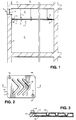
- a room R contains a cooling ceiling C suspended from the top surface T of the room, e.g. an overlying floor or the roof of the building.
- the ceiling C is made up of panels P located in the squares of a grid frame defined by T bars 2 which are connected to hanger rods 1 secured to the top surface T of the room.
- the space from the surface T to the top of the ceiling 1 defines a building services space 6, which, as shown includes an inlet 3 in the outer wall 4 and contains a filter 7; at least one grid outlet 5 is present in the ceiling C to draw air from the duct 6 into the space of the room R. (The space 6 is an optional feature).
- Each panel P comprises a lower wall 10 and an upper wall 11 which are sealed at their margins 12 to form a slab like structure.
- a fluid medium, W typically water
- W is present in the panel and enters via an inlet 13 and exits via an outlet 14.
- the water is supplied via pipes and pumps etc. not shown. It will be clear from the shape of the panel that the water W is in contact with all of the lower surface 10 so that an effective heat transfer can take place between the heat in the air of the room R and the flowing water W.
- the panels P are empty but as shown in the embodiments of Figure 3 and in Figure 5 the panels may have internal structures to guide the water flow so that it is spread evenly across the panels.
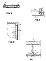
- the upper wall 12 is formed with interior baffles 15 arranged in say a herringbone pattern as seen in plan view, to cause the water W to spread evenly thinly over the lower surface 10.
- the inlet is set at one end of a pipe 16 the longer side of which has perforations 17 to release small diameter parallel streams.
- FIG. 7 there are two panels P1, which at one end, the left hand end, as shown, have a projecting ledge or shoulder 18 and at the other a recess 19, dimensioned so that they can be abutted and present a continuous appearance.
- the top wall 11 has an end upper hook 20 which engages the end of a hanger rod 1.
- a panel of the invention preferably has a thickness from about 6mm to about 12mm.
- the structure is made of material which has mechanical strength so that it can support its own weight and the weight of the water and is shaped so that substantially all of the top and bottom surfaces are exposed to air to provide heat transfer.
- 80% or more of the energy transfer is by heat radiation and 20% or less by heat convention.
- the water in a panel is at a pressure of 1 bar or less, preferably of about 0.2 bar, (which is much less than the pressurised water in say a floor or wall mounted central heating system).
- the energy transfer ranges from about 60 to about 150 W/m 2 .
- the air is relatively still and not dried out.
- the heat in the water W may be extracted for use (or storage) in a suitable medium. It may however be used to heat air, e.g. incoming air in the duct 6.
- the invention works by extracting heat from a room without causing extraction of the moisture at the same time, it provides an efficient method of controlling indoor climates without affecting the humidity. Because there is no need for much air replacement it is particularly suitable for sterile areas, e.g. hospital operating theatres. The apparatus is silent in use and environmentally acceptable.
- the invention is not limited to the embodiment shown.
- the panels can be moulded to the shape of the room and need not be rectangular as seen in plan.
Landscapes
- Engineering & Computer Science (AREA)
- General Engineering & Computer Science (AREA)
- Mechanical Engineering (AREA)
- Chemical & Material Sciences (AREA)
- Combustion & Propulsion (AREA)
- Thermal Sciences (AREA)
- Life Sciences & Earth Sciences (AREA)
- Physics & Mathematics (AREA)
- Sustainable Development (AREA)
- Building Environments (AREA)
- Duct Arrangements (AREA)
- Control Of Temperature (AREA)
- Valve Device For Special Equipments (AREA)
- Inorganic Insulating Materials (AREA)
- Steam Or Hot-Water Central Heating Systems (AREA)
Claims (13)
- Gebäude, umfassend einen Raum (R) mit einer Oberseite (T), einer Kühldecke (C), die an einer Aufhängevorrichtung (1) unter der Oberseite (T) aufgehängt ist, wobei die Decke (C) ein oder mehrere Tafeln (P) umfaßt, die aus einem Kunststoffmaterial bestehen und ein Fluidmedium (W) enthalten, wobei das Fluidmedium (W) im wesentlichen mit der gesamten Unterseite (10) der Tafeln (P) Kontakt hat, so daß im wesentlichen über die gesamte Unterseite (10) Wärme von dem Raum (R) zu dem Medium (W) übertragen wird, und wobei die Unterseite (C) eine strukturierte Lackoberfläche hat, um die Fläche zu vergrößern und Zonen zu vermeiden, in denen ein solcher Temperaturunterschied vorliegt, daß es zu Kondensation kommen kann.
- Gebäude nach Anspruch 1, wobei die Unterseite (10) der Tafel (P) so profiliert ist, daß ihre Fläche vergrößert wird.
- Gebäude nach Anspruch 1 oder 2, wobei die Tafel (P) aus einem Material mit einer ausreichenden mechanischen Festigkeit gebildet ist, um das Gewicht dieser Tafel (P) und des Fluidmediums (W) darin verzerrungsfrei abzustützen.
- Gebäude nach einem der vorhergehenden Ansprüche, wobei die Tafeln (P) in einem Rasterrahmen stecken, der zu diesem Zweck durch T-Stäbe (2) gebildet ist, mit denen die Aufhängevorrichtung (1) verbunden ist.
- Gebäude nach einem der Ansprüche 1 bis 3, wobei Hakenvorrichtungen (20) an den Tafeln (P1) vorhanden sind, die mit der Aufhängevorrichtung (1) verbunden sind, so daß die Tafeln (P1) unmittelbar an der Aufhängevorrichtung (1) hängen.
- Gebäude nach Anspruch 5, wobei benachbarte Tafeln (P1) so geformt (18, 19) sind, daß ihre Unterseiten (10) eine im wesentliche kontinuierliche Fläche bilden.
- Gebäude nach einem der vorhergehenden Ansprüche, wobei die Decke (C) die untere Wand eines Gebäudeversorgungskanals (6) darstellt.
- Gebäude nach Anspruch 7, das einen Einlaß (3) für Frischluft in den Kanal (6) aufweist, wobei die Deckentafeln (P) so angeordnet sind, daß sie Wärme in bezug auf die einströmende Luft von der Oberseite (11) der Tafel (P) übertragen.
- Verfahren zur Kühlung eines Raumes (R) in einem Gebäude, wobei der Raum (R) eine Decke (C) aufweist, die an einer Aufhängevorrichtung (1) unter der Oberseite (T) des Raumes (R) hängt, wobei die Decke (C) aus einer oder mehreren Tafeln (P) gebildet ist, die aus einem Kunststoffmaterial bestehen, durch das ein Fluidmedium (W) geleitet wird, so daß das Fluidmedium (W) im wesentlichen mit der gesamten Unterseite (10) der Tafeln (P) Kontakt hat, und wobei die Unterseite (10) eine strukurierte Lackoberfläche hat, so daß ihr Fläche vergrößert wird und es im wesentlichen keine Temperaturdifferenz über die Unterseite gibt, so daß keine Kondensation auftreten kann.
- Verfahren nach Anspruch 9, wobei das Fluidmedium mit einem Druck von weniger als etwa 1 bar geleitet wird.
- Verfahren nach Anspruch 10, wobei das Fluidmedium mit einem Druck von etwa 0,2 bar geleitet wird.
- Tafel (P) zur Verwendung in einer Hängekühldecke (C), wobei die Tafel aus einem Kunststoffmaterial gebildet ist und Mittel (13, 14) für den Durchfluß eines Fluidmediums (W) aufweist, wobei die Tafel (P) so geformt ist, daß das Fluidmedium (W) bei Gebrauch mit im wesentlichen der gesamten Unterseite (10) der Tafel (P) Kontakt hat, und wobei die Unterseite (10) eine strukurierte Lackoberfläche aufweist, um die Fläche zu vergrößern und Zonen zu vermeiden, bei denen eine solche Temperaturdifferenz vorliegt, daß Kondensation auftreten kann.
- Tafel nach Anspruch 12, einschließlich Hakenvorrichtungen (20) für eine direkte Verbindung mit der Aufhängevorrichtung (1).
Applications Claiming Priority (5)
| Application Number | Priority Date | Filing Date | Title |
|---|---|---|---|
| SE9200859 | 1992-03-20 | ||
| SE9200859A SE9200859D0 (sv) | 1992-03-20 | 1992-03-20 | Klimat-tak |
| GB9303739A GB2265703B (en) | 1992-03-20 | 1993-02-24 | Temperature control |
| GB9303739 | 1993-02-24 | ||
| PCT/GB1993/000588 WO1993019330A1 (en) | 1992-03-20 | 1993-03-22 | Temperature control |
Publications (2)
| Publication Number | Publication Date |
|---|---|
| EP0633994A1 EP0633994A1 (de) | 1995-01-18 |
| EP0633994B1 true EP0633994B1 (de) | 1996-09-25 |
Family
ID=26302499
Family Applications (1)
| Application Number | Title | Priority Date | Filing Date |
|---|---|---|---|
| EP93906725A Expired - Lifetime EP0633994B1 (de) | 1992-03-20 | 1993-03-22 | Temperaturregelung |
Country Status (6)
| Country | Link |
|---|---|
| US (1) | US5632327A (de) |
| EP (1) | EP0633994B1 (de) |
| AU (1) | AU670073B2 (de) |
| DE (1) | DE69305074T2 (de) |
| ES (1) | ES2095639T3 (de) |
| GR (1) | GR3022141T3 (de) |
Cited By (1)
| Publication number | Priority date | Publication date | Assignee | Title |
|---|---|---|---|---|
| EP2180108A1 (de) | 2008-10-21 | 2010-04-28 | Autarkis B.V. | Deckenplattenaktivierung und modulare Decke mit diesen Platten |
Families Citing this family (6)
| Publication number | Priority date | Publication date | Assignee | Title |
|---|---|---|---|---|
| US6170561B1 (en) * | 1999-09-08 | 2001-01-09 | O'grady Mark | Heat absorbent device for backup cooling |
| WO2001069139A1 (en) * | 2000-03-17 | 2001-09-20 | Sunarc Structures Inc. | Dynamic heating and cooling of a building using liquid foam |
| BE1013874A3 (nl) * | 2000-12-15 | 2002-11-05 | Stroobants Marcel | Decoratieve radiator. |
| US20140352915A1 (en) * | 2013-05-31 | 2014-12-04 | Narayanan Raju | Radiant thermal systems and methods for enclosed structures |
| JP6197006B2 (ja) * | 2015-07-23 | 2017-09-13 | 株式会社セントラルユニ | 輻射空調パネル |
| JP6197139B1 (ja) * | 2017-06-19 | 2017-09-13 | 株式会社セントラルユニ | 輻射空調パネル |
Family Cites Families (12)
| Publication number | Priority date | Publication date | Assignee | Title |
|---|---|---|---|---|
| GB778317A (en) * | 1954-01-09 | 1957-07-03 | Feller Fritz | A ceiling, wall or floor heating system |
| CH363775A (de) * | 1958-06-24 | 1962-08-15 | Stramax Ag | Anlage zur Beeinflussung der Temperatur eines Raumes |
| GB1180607A (en) * | 1966-05-16 | 1970-02-04 | Tranter Mfg Inc | Thermal Transfer Ceiling Structure |
| GB1497261A (en) * | 1975-01-16 | 1978-01-05 | Eisler P | Cooling apparatus |
| CA1061774A (en) * | 1976-12-07 | 1979-09-04 | R. Mark J. Cairenius | Heat transfering wall panels |
| US4155887A (en) * | 1978-02-07 | 1979-05-22 | Hetson George W | Stabilized insulating latex paint composition and method of manufacture |
| EP0464874B1 (de) * | 1987-11-17 | 1996-02-28 | Shinwa Sangyo Co., Ltd. | Wärmetauscher für einen Kühlturm |
| DE3809060A1 (de) * | 1988-03-18 | 1989-09-28 | Timmer Ingbuero Gmbh | System zum temperieren von raeumen eines gebaeudes |
| US4945981A (en) * | 1990-01-26 | 1990-08-07 | General Motors Corporation | Oil cooler |
| JP3128127B2 (ja) * | 1990-03-28 | 2001-01-29 | 東芝キャリア株式会社 | 空気調和装置 |
| US5166862A (en) * | 1990-09-28 | 1992-11-24 | Square D Company | Panel for mounting electronics |
| DE69214796T2 (de) * | 1991-08-20 | 1997-05-28 | Koester Helmut | Kühlanlage |
-
1993
- 1993-03-22 EP EP93906725A patent/EP0633994B1/de not_active Expired - Lifetime
- 1993-03-22 US US08/338,445 patent/US5632327A/en not_active Expired - Fee Related
- 1993-03-22 DE DE69305074T patent/DE69305074T2/de not_active Expired - Fee Related
- 1993-03-22 AU AU37625/93A patent/AU670073B2/en not_active Ceased
- 1993-03-22 ES ES93906725T patent/ES2095639T3/es not_active Expired - Lifetime
-
1996
- 1996-12-23 GR GR960403587T patent/GR3022141T3/el unknown
Cited By (1)
| Publication number | Priority date | Publication date | Assignee | Title |
|---|---|---|---|---|
| EP2180108A1 (de) | 2008-10-21 | 2010-04-28 | Autarkis B.V. | Deckenplattenaktivierung und modulare Decke mit diesen Platten |
Also Published As
| Publication number | Publication date |
|---|---|
| DE69305074T2 (de) | 1997-04-17 |
| GR3022141T3 (en) | 1997-03-31 |
| AU670073B2 (en) | 1996-07-04 |
| US5632327A (en) | 1997-05-27 |
| AU3762593A (en) | 1993-10-21 |
| ES2095639T3 (es) | 1997-02-16 |
| DE69305074D1 (de) | 1996-10-31 |
| EP0633994A1 (de) | 1995-01-18 |
Similar Documents
| Publication | Publication Date | Title |
|---|---|---|
| US4603618A (en) | Air filtering and distribution for laminar flow clean room | |
| FI107078B (fi) | Rakennuksen lämmitys- ja ilmastointijärjestelmä | |
| EP2686616B1 (de) | Verdrängungslüftungssystem und einlassteil für ein solches system | |
| EP0633994B1 (de) | Temperaturregelung | |
| EP1442244A1 (de) | Biegsamer luftkanal mit staub- und kondensationsabweisung | |
| NO119578B (de) | ||
| WO1993019330A1 (en) | Temperature control | |
| JP2004522926A (ja) | 空気調整装置 | |
| RU96107409A (ru) | Теплоизолирующая внешняя стена здания | |
| US20040251009A1 (en) | Panel for a suspended heating and/or cooling ceiling | |
| JP2001355894A (ja) | 輻射式空調システム | |
| RU2159899C2 (ru) | Система отопления и вентиляции зданий | |
| US20090084521A1 (en) | Temperature and vapour pressure regulation device for a structure | |
| KR101332379B1 (ko) | 냉난방 복사 패널 | |
| JPH11294798A (ja) | 空調システム及び空調方法 | |
| JPS62223547A (ja) | 換気システム | |
| EP1772568A1 (de) | Deckenpaneelen, lüftende Decke und ein Verfahren zur Herstellung der Deckenpaneelen | |
| JP2004183407A (ja) | 外壁構造および外壁用の複合建築パネル | |
| JP2564365B2 (ja) | 家 屋 | |
| FI76878B (fi) | Foerfarande foer reglering av luftvaexling av byggnad och en konstruktion foer tillaempning av foerfarandet. | |
| JP2564363B2 (ja) | 家 屋 | |
| KR200416121Y1 (ko) | 결로방지용 단열보강재 | |
| RU159427U1 (ru) | Теплораспределяющая панель | |
| WO2023281390A1 (en) | Aeraulic device and radiant ceiling thermal system with internal air mixing | |
| WO1990011476A1 (en) | Method and arrangement for controlling the temperature in buildings |
Legal Events
| Date | Code | Title | Description |
|---|---|---|---|
| PUAI | Public reference made under article 153(3) epc to a published international application that has entered the european phase |
Free format text: ORIGINAL CODE: 0009012 |
|
| 17P | Request for examination filed |
Effective date: 19941020 |
|
| AK | Designated contracting states |
Kind code of ref document: A1 Designated state(s): BE CH DE DK ES FR GB GR IE IT LI NL SE |
|
| 17Q | First examination report despatched |
Effective date: 19950215 |
|
| GRAG | Despatch of communication of intention to grant |
Free format text: ORIGINAL CODE: EPIDOS AGRA |
|
| GRAH | Despatch of communication of intention to grant a patent |
Free format text: ORIGINAL CODE: EPIDOS IGRA |
|
| GRAA | (expected) grant |
Free format text: ORIGINAL CODE: 0009210 |
|
| GRAH | Despatch of communication of intention to grant a patent |
Free format text: ORIGINAL CODE: EPIDOS IGRA |
|
| AK | Designated contracting states |
Kind code of ref document: B1 Designated state(s): BE CH DE DK ES FR GB GR IE IT LI NL SE |
|
| PG25 | Lapsed in a contracting state [announced via postgrant information from national office to epo] |
Ref country code: NL Free format text: LAPSE BECAUSE OF FAILURE TO SUBMIT A TRANSLATION OF THE DESCRIPTION OR TO PAY THE FEE WITHIN THE PRESCRIBED TIME-LIMIT Effective date: 19960925 Ref country code: LI Effective date: 19960925 Ref country code: DK Effective date: 19960925 Ref country code: CH Effective date: 19960925 Ref country code: BE Effective date: 19960925 |
|
| REF | Corresponds to: |
Ref document number: 69305074 Country of ref document: DE Date of ref document: 19961031 |
|
| REG | Reference to a national code |
Ref country code: IE Ref legal event code: FG4D Free format text: 70033 |
|
| ITF | It: translation for a ep patent filed | ||
| ET | Fr: translation filed | ||
| REG | Reference to a national code |
Ref country code: ES Ref legal event code: FG2A Ref document number: 2095639 Country of ref document: ES Kind code of ref document: T3 |
|
| REG | Reference to a national code |
Ref country code: GR Ref legal event code: FG4A Free format text: 3022141 |
|
| NLV1 | Nl: lapsed or annulled due to failure to fulfill the requirements of art. 29p and 29m of the patents act | ||
| PG25 | Lapsed in a contracting state [announced via postgrant information from national office to epo] |
Ref country code: IE Free format text: LAPSE BECAUSE OF NON-PAYMENT OF DUE FEES Effective date: 19970322 |
|
| REG | Reference to a national code |
Ref country code: CH Ref legal event code: PL |
|
| PLBE | No opposition filed within time limit |
Free format text: ORIGINAL CODE: 0009261 |
|
| STAA | Information on the status of an ep patent application or granted ep patent |
Free format text: STATUS: NO OPPOSITION FILED WITHIN TIME LIMIT |
|
| 26N | No opposition filed | ||
| REG | Reference to a national code |
Ref country code: GB Ref legal event code: IF02 |
|
| PGFP | Annual fee paid to national office [announced via postgrant information from national office to epo] |
Ref country code: FR Payment date: 20050324 Year of fee payment: 13 |
|
| PGFP | Annual fee paid to national office [announced via postgrant information from national office to epo] |
Ref country code: GR Payment date: 20050329 Year of fee payment: 13 |
|
| PGFP | Annual fee paid to national office [announced via postgrant information from national office to epo] |
Ref country code: SE Payment date: 20050330 Year of fee payment: 13 |
|
| PGFP | Annual fee paid to national office [announced via postgrant information from national office to epo] |
Ref country code: ES Payment date: 20050405 Year of fee payment: 13 |
|
| PGFP | Annual fee paid to national office [announced via postgrant information from national office to epo] |
Ref country code: GB Payment date: 20050420 Year of fee payment: 13 |
|
| PGFP | Annual fee paid to national office [announced via postgrant information from national office to epo] |
Ref country code: DE Payment date: 20050422 Year of fee payment: 13 |
|
| PG25 | Lapsed in a contracting state [announced via postgrant information from national office to epo] |
Ref country code: GB Free format text: LAPSE BECAUSE OF NON-PAYMENT OF DUE FEES Effective date: 20060322 |
|
| PG25 | Lapsed in a contracting state [announced via postgrant information from national office to epo] |
Ref country code: SE Free format text: LAPSE BECAUSE OF NON-PAYMENT OF DUE FEES Effective date: 20060323 Ref country code: ES Free format text: LAPSE BECAUSE OF NON-PAYMENT OF DUE FEES Effective date: 20060323 |
|
| PGFP | Annual fee paid to national office [announced via postgrant information from national office to epo] |
Ref country code: IT Payment date: 20060331 Year of fee payment: 14 |
|
| PG25 | Lapsed in a contracting state [announced via postgrant information from national office to epo] |
Ref country code: DE Free format text: LAPSE BECAUSE OF NON-PAYMENT OF DUE FEES Effective date: 20061003 |
|
| EUG | Se: european patent has lapsed | ||
| GBPC | Gb: european patent ceased through non-payment of renewal fee |
Effective date: 20060322 |
|
| REG | Reference to a national code |
Ref country code: FR Ref legal event code: ST Effective date: 20061130 |
|
| REG | Reference to a national code |
Ref country code: ES Ref legal event code: FD2A Effective date: 20060323 |
|
| PG25 | Lapsed in a contracting state [announced via postgrant information from national office to epo] |
Ref country code: FR Free format text: LAPSE BECAUSE OF NON-PAYMENT OF DUE FEES Effective date: 20060331 |
|
| PG25 | Lapsed in a contracting state [announced via postgrant information from national office to epo] |
Ref country code: GR Free format text: LAPSE BECAUSE OF NON-PAYMENT OF DUE FEES Effective date: 20061002 |
|
| PG25 | Lapsed in a contracting state [announced via postgrant information from national office to epo] |
Ref country code: IT Free format text: LAPSE BECAUSE OF NON-PAYMENT OF DUE FEES Effective date: 20070322 |