EP0633965B1 - Dichtungsvorrichtung für Abdichtung von Dehnungsfugen in Betonstaudämmen und Einrichtungsverfahren derselben - Google Patents
Dichtungsvorrichtung für Abdichtung von Dehnungsfugen in Betonstaudämmen und Einrichtungsverfahren derselben Download PDFInfo
- Publication number
- EP0633965B1 EP0633965B1 EP93907701A EP93907701A EP0633965B1 EP 0633965 B1 EP0633965 B1 EP 0633965B1 EP 93907701 A EP93907701 A EP 93907701A EP 93907701 A EP93907701 A EP 93907701A EP 0633965 B1 EP0633965 B1 EP 0633965B1
- Authority
- EP
- European Patent Office
- Prior art keywords
- sealing device
- cell
- hole
- end member
- expansion joint
- Prior art date
- Legal status (The legal status is an assumption and is not a legal conclusion. Google has not performed a legal analysis and makes no representation as to the accuracy of the status listed.)
- Expired - Lifetime
Links
- 238000007789 sealing Methods 0.000 title claims abstract description 133
- 238000000034 method Methods 0.000 title claims abstract description 41
- 230000002787 reinforcement Effects 0.000 claims abstract description 68
- 239000012530 fluid Substances 0.000 claims abstract description 30
- XLYOFNOQVPJJNP-UHFFFAOYSA-N water Substances O XLYOFNOQVPJJNP-UHFFFAOYSA-N 0.000 claims abstract description 19
- 230000002093 peripheral effect Effects 0.000 claims abstract description 10
- 238000009434 installation Methods 0.000 claims description 33
- 230000003014 reinforcing effect Effects 0.000 claims description 12
- 238000003780 insertion Methods 0.000 claims description 11
- 230000037431 insertion Effects 0.000 claims description 11
- 239000000463 material Substances 0.000 claims description 11
- 238000005520 cutting process Methods 0.000 claims description 6
- 229920001971 elastomer Polymers 0.000 claims description 5
- 239000013013 elastic material Substances 0.000 claims description 3
- 230000008878 coupling Effects 0.000 claims 3
- 238000010168 coupling process Methods 0.000 claims 3
- 238000005859 coupling reaction Methods 0.000 claims 3
- 238000004873 anchoring Methods 0.000 claims 1
- 239000012858 resilient material Substances 0.000 abstract 1
- 238000005553 drilling Methods 0.000 description 39
- 229910003460 diamond Inorganic materials 0.000 description 12
- 239000010432 diamond Substances 0.000 description 12
- 238000010276 construction Methods 0.000 description 9
- 239000004459 forage Substances 0.000 description 6
- 239000007788 liquid Substances 0.000 description 6
- 239000004033 plastic Substances 0.000 description 6
- 230000008439 repair process Effects 0.000 description 6
- 238000011144 upstream manufacturing Methods 0.000 description 6
- 239000011440 grout Substances 0.000 description 5
- 230000001070 adhesive effect Effects 0.000 description 4
- 230000000694 effects Effects 0.000 description 4
- 239000000853 adhesive Substances 0.000 description 3
- 210000003739 neck Anatomy 0.000 description 3
- 239000004568 cement Substances 0.000 description 2
- 210000003141 lower extremity Anatomy 0.000 description 2
- 238000011084 recovery Methods 0.000 description 2
- 229910001220 stainless steel Inorganic materials 0.000 description 2
- 239000010935 stainless steel Substances 0.000 description 2
- 230000008961 swelling Effects 0.000 description 2
- 238000003466 welding Methods 0.000 description 2
- 239000004606 Fillers/Extenders Substances 0.000 description 1
- 235000019738 Limestone Nutrition 0.000 description 1
- 239000004677 Nylon Substances 0.000 description 1
- 241000425571 Trepanes Species 0.000 description 1
- 240000008042 Zea mays Species 0.000 description 1
- 230000005856 abnormality Effects 0.000 description 1
- 230000002528 anti-freeze Effects 0.000 description 1
- 230000003542 behavioural effect Effects 0.000 description 1
- 239000000440 bentonite Substances 0.000 description 1
- 229910000278 bentonite Inorganic materials 0.000 description 1
- SVPXDRXYRYOSEX-UHFFFAOYSA-N bentoquatam Chemical compound O.O=[Si]=O.O=[Al]O[Al]=O SVPXDRXYRYOSEX-UHFFFAOYSA-N 0.000 description 1
- 230000005540 biological transmission Effects 0.000 description 1
- 238000006243 chemical reaction Methods 0.000 description 1
- 238000007796 conventional method Methods 0.000 description 1
- 238000005336 cracking Methods 0.000 description 1
- 230000002950 deficient Effects 0.000 description 1
- 238000006073 displacement reaction Methods 0.000 description 1
- 230000007613 environmental effect Effects 0.000 description 1
- 238000009415 formwork Methods 0.000 description 1
- 230000008014 freezing Effects 0.000 description 1
- 238000007710 freezing Methods 0.000 description 1
- 239000003292 glue Substances 0.000 description 1
- 230000005484 gravity Effects 0.000 description 1
- 230000008595 infiltration Effects 0.000 description 1
- 238000001764 infiltration Methods 0.000 description 1
- 238000002347 injection Methods 0.000 description 1
- 239000007924 injection Substances 0.000 description 1
- 238000005304 joining Methods 0.000 description 1
- 239000006028 limestone Substances 0.000 description 1
- 230000007774 longterm Effects 0.000 description 1
- 239000000314 lubricant Substances 0.000 description 1
- 238000004519 manufacturing process Methods 0.000 description 1
- 239000002184 metal Substances 0.000 description 1
- 238000012986 modification Methods 0.000 description 1
- 230000004048 modification Effects 0.000 description 1
- 229920001778 nylon Polymers 0.000 description 1
- 210000004197 pelvis Anatomy 0.000 description 1
- 229920000642 polymer Polymers 0.000 description 1
- 239000011253 protective coating Substances 0.000 description 1
- 239000011347 resin Substances 0.000 description 1
- 229920005989 resin Polymers 0.000 description 1
- 230000000452 restraining effect Effects 0.000 description 1
- 230000000717 retained effect Effects 0.000 description 1
- 239000004575 stone Substances 0.000 description 1
- 239000000126 substance Substances 0.000 description 1
- 229920003051 synthetic elastomer Polymers 0.000 description 1
- 229920002994 synthetic fiber Polymers 0.000 description 1
- 238000012360 testing method Methods 0.000 description 1
- 238000013519 translation Methods 0.000 description 1
- 210000001364 upper extremity Anatomy 0.000 description 1
- 238000004078 waterproofing Methods 0.000 description 1
Images


Classifications
-
- E—FIXED CONSTRUCTIONS
- E21—EARTH OR ROCK DRILLING; MINING
- E21B—EARTH OR ROCK DRILLING; OBTAINING OIL, GAS, WATER, SOLUBLE OR MELTABLE MATERIALS OR A SLURRY OF MINERALS FROM WELLS
- E21B7/00—Special methods or apparatus for drilling
- E21B7/28—Enlarging drilled holes, e.g. by counterboring
-
- B—PERFORMING OPERATIONS; TRANSPORTING
- B23—MACHINE TOOLS; METAL-WORKING NOT OTHERWISE PROVIDED FOR
- B23B—TURNING; BORING
- B23B47/00—Constructional features of components specially designed for boring or drilling machines; Accessories therefor
- B23B47/28—Drill jigs for workpieces
-
- E—FIXED CONSTRUCTIONS
- E02—HYDRAULIC ENGINEERING; FOUNDATIONS; SOIL SHIFTING
- E02B—HYDRAULIC ENGINEERING
- E02B3/00—Engineering works in connection with control or use of streams, rivers, coasts, or other marine sites; Sealings or joints for engineering works in general
- E02B3/16—Sealings or joints
-
- E—FIXED CONSTRUCTIONS
- E21—EARTH OR ROCK DRILLING; MINING
- E21B—EARTH OR ROCK DRILLING; OBTAINING OIL, GAS, WATER, SOLUBLE OR MELTABLE MATERIALS OR A SLURRY OF MINERALS FROM WELLS
- E21B17/00—Drilling rods or pipes; Flexible drill strings; Kellies; Drill collars; Sucker rods; Cables; Casings; Tubings
- E21B17/10—Wear protectors; Centralising devices, e.g. stabilisers
- E21B17/1057—Centralising devices with rollers or with a relatively rotating sleeve
-
- E—FIXED CONSTRUCTIONS
- E21—EARTH OR ROCK DRILLING; MINING
- E21B—EARTH OR ROCK DRILLING; OBTAINING OIL, GAS, WATER, SOLUBLE OR MELTABLE MATERIALS OR A SLURRY OF MINERALS FROM WELLS
- E21B7/00—Special methods or apparatus for drilling
- E21B7/001—Drilling a non circular hole
-
- B—PERFORMING OPERATIONS; TRANSPORTING
- B23—MACHINE TOOLS; METAL-WORKING NOT OTHERWISE PROVIDED FOR
- B23B—TURNING; BORING
- B23B2247/00—Details of drilling jigs
- B23B2247/04—Jigs using one or more holes as datums for drilling further holes
Definitions
- the present invention deals with concrete, such as gravity dams and, more particularly, a sealing device for sealing expansion joints cut in dams of this type.
- U.S. Patent No. 4,655,638 discloses a method waterproofing of an opening in a concrete dam. According to this method, a hole is drilled on the opening to receive a member tubular and elastic comprising an impervious inner layer and a outer layer coated with a resin having adhesive properties to provide good adhesion of the tubular member to the walls of the hole.
- the tubular member has an open upper end and an end lower closed. Once the installation step is completed, the tubular member is filled with a non-gaseous and elastic fluid.
- An inversion device operable to direct a pressurized fluid inside the tubular member is used to install the latter in the hole.
- No. 3,342,033 discloses a sealing device comprising a flexible bag used to form a seal at the junction of a pole and a wall.
- the bag is installed in the space defined by a longitudinal embedding formed in the post and a groove extending the along one end of the wall. Once in position, the bag is filled with a hardening material, such as cement.
- Concrete dams ie dams, arch dams (vaulted), or even joint dams may suffer from behavior such as, for dams without joints, cracking of the dam due to work, or the swelling of the dam due, for example, to chemical reactions in the dam.
- seals may leak.
- dams To produce expansion joints in concrete dams, it has also been proposed to build dams into several sections separate and nested and separated by a space empty that serves as a game when moving .. various sections of the dam. Each section of dam is cased independently with nested spacing to produce the seal. For seal the end of the seal located on the side of water, we install sealing slats which adjust when the sections of the dam are move relative to each other so as to that the dam retains its waterproof character. As the spaces between the various sections of the dam that serve as seals fill up with the time of limestone and others, the vacuum is blocked, eliminating the play between the dam sections and, therefore, the expansion joint itself.
- the present invention therefore aims to develop a sealing device for concrete structures.
- the present invention also aims to develop a sealing device for sealing of expansion joints cut in concrete dams that adapts to the movements of the barrage.
- the present invention also aims to develop a sealing device for concrete structures that are of economical manufacture and easy installation, safe and relatively inexpensive to replace less effective sealing devices used for this purpose day.
- the sealing of cuts made in dams to correct behavioral abnormalities wants to be accomplished by a simple method and relatively inexpensive using a seal effective sealing and also relatively little expensive.
- the present invention also aims to develop a method to create in a concrete dam an expansion joint characterized by a sealing device according to the present invention.
- a method is also proposed for replace a sealing device according to the present invention by a new seal sealing.
- a method is also proposed to prevent the installation of a cofferdam upstream of the dam.
- the present invention also aims to develop a guidance device for overlapping and parallel drilling to allow, inter alia, the installation of in a concrete dam an expansion joint characterized by a following sealing device the present invention.
- the invention proposes a sealing device for sealing of an opening made in a concrete structure
- a sealing device for sealing of an opening made in a concrete structure
- a cell made of an elastic material and including at least one tubular section, the cell being provided at its upper ends and bottom respectively of a mouthpiece upper rigid and lower end rigid, the bottom surface of the mouthpiece lower being formed to facilitate the insertion of the sealing device in hole on the opening, means that are not extensible upper and lower tips for prevent longitudinal stretching of the cell
- the cell including means of reinforcement spaced apart from each other and arranged opposite the opening to prevent the deformation of the cell in the opening, a continuous peripheral space being defined on the cell between lower ends of the reinforcement means and the upper end of the mouthpiece lower, and means to allow positioning and the installation of the sealing device.
- the end pieces upper and lower each at least one cylindrical section, the cell forming a cylinder covering fixed way at its upper ends and lower the cylindrical sections respective upper and lower ends
- the sections cylindrical upper and lower ends provide each of the restraining stops on their respective periphery which respectively engage the ends upper and lower cell cylindrical to ensure their assembly, retaining collars being mounted around the upper and lower extremities of the cell to reinforce the said assembly.
- the bottom nozzle includes a semi-spherical section to the lower end of its section cylindrical.
- the means extensible include at least one cable mounted tightly in the cell, the ends of each cable being attached to their respective mouthpiece using means attachment
- Said means fasteners include bolts to eyelet.
- the upper endpiece includes a retaining ring mounted to inside its cylindrical section, the ring restraint practicing an opening central threaded receiving a plug, the cap including a connected opening to a manifold that includes a valve to allow the entry of at least one fluid in the cell and ensure the maintaining the desired fluid pressure in the cell .
- the cell is made of a rubbery material.
- the upper end includes means for the manipulation of the sealing device and for its attachment to the work.
- the means of reinforcement include two reinforcements longitudinals arranged externally on both sides of the cell.
- the reinforcements are made of a rigid material and are glued on the cell.
- said means to allow positioning and the installation of the sealing device include guide rings arranged externally along each of the reinforcements and engaging in the opening, a pulley mounted vertically at the bottom of the bottom nozzle, and a cable engaging the pulley and going up from and other cell while passing through guide rings respective reinforcements.
- Said rings of guidance each have an arched base arranged between the cell and a backup respective
- the device installation includes guide rings arranged along each of the reinforcements and engaging in the opening, at least one guide rod passing through guide rings respective of one of the two reinforcements and including a threaded lower end, a guide sleeve mounted at the bottom of the reinforcement and providing a central opening threaded to receive a guide rod respectively.
- Said rings of guidance each have an arched base arranged between the cell and a backup respective, a guide rod being provided for the guide rings of each of the two reinforcements
- a second and a third holes are drilled with overlap on both sides of the first hole to facilitate steps b) and d).
- a fourth hole (74) is drilled, this fourth hole being intended to receive a second device similar to that of the first hole, and in which, in step d), the completion cutoff of the expansion joint also joins the fourth hole.
- a second sealing device is installed in the fourth hole and is then filled with a suitable fluid.
- the second sealing device is filled under pressure required using at least one suitable fluid.
- the sealing device includes an installation device including guide rings arranged externally along each of the reinforcement means, a pulley being vertically mounted at the bottom of the mouthpiece lower, and a cable being engaged on the pulley and going up from hand and else from the cell while moving on to through respective guide rings reinforcement means, the method including, in step (b), the introduction of guide rings in the second and third hole.
- the sealing device includes an installation device including guide rings arranged externally along each reinforcement means, at least one rod guide passing through the rings respective guidance of one of the means of reinforcement and including one end lower threaded, a guide sleeve mounted at the bottom of the reinforcing means and providing a central threaded opening receiving a respective guide rod, the method comprising, in step b), the introduction of the guide rod and its guide rings in one of second and third holes the fixing the sealing device to the work, then unscrewing the stem of guiding the guide sleeve, and finally the withdrawal of the guide rod from his hole.
- a guide rod (60) is used for each of the second and third holes each guide pin being associated with one of the reinforcement means.
- Installation and tensioning the second sealing device include drilling a second hole on the expansion joint intended to receive the second sealing device and the filling of the second sealing device under pressure required using the fluid appropriate.
- Step d) is to depressurize the second device sealing.
- Installation and tensioning the second sealing device include drilling a second hole on the expansion joint intended to receive the second sealing device and the filling of the second sealing device under pressure required using the fluid appropriate.
- the figures 1 to 5 illustrate a seal J for joints of expansion E practiced in a concrete structure such as a weight dam B.
- a seal J for joints of expansion E practiced in a concrete structure such as a weight dam B.
- the cutting of the joint E expansion in the B dam and the installation of the seal J in the expansion joint E will be described below in detail with reference Figures 5 to 7.
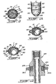
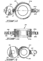
- seal J seal J comprises a tubular cylindrical cell 10 made of a rubbery material.
- Cell 10 is open at its upper and lower ends 12 and 14, respectively.
- Cell 10 can be made from a rectangular height panel equal to the height of the desired cell and width greater than the circumference of this cell. So, cell 10 is built in folding the panel back to make a tube while overlapping the longitudinal edges of the panel. The overlapping portions of the panel are affixed to one another with an adhesive.
- a rigid cylindrical tip 16 is inserted so fixed in the upper end 12 of the cell 10 by means of retainers 18 provided on the periphery of the upper tip 16 and which penetrate partially in the cell 10 to grip it.
- the upper nozzle 16 is close to its edge free upper four holes 19 arranged so equidistant along the periphery of the tip 16. Two of the 19 holes are used for handling of the seal J, for example to using a crane; or a scaffolding equipped with a reel, for its insertion in the joint E expansion, while the other two holes 19 used to attach the seal J to the top of the dam B so that it hangs in the hole who receives it.
- a rigid lower end 20 having a cylindrical upper section and a section lower semi-spherical shape is inserted into the lower end 14 of the cell 10 and there is similarly fixed to the upper nozzle 16, that is, with retainers 22 practiced on the outer peripheral surface of the bottom nozzle 20 and which cling to the inner surface of the lower end 14 of cell 10.
- Retainers 24 are positioned and put in tension around the end lower 14 of the cell 10 opposite the section cylindrical of the lower nozzle 20 so as to produce a stronger connection between the cell 10 and the lower end 20.
- Two reinforcements 26 of elongated shape and section shaped circle segment are mounted from opposite and longitudinal way on both sides on the outside of the cell 10 (see Figure 2).
- These reinforcements 26 can be made of a hard material (such as "cord puller") so as to prevent a radial deflection of cell 10 at the level of installations of these reinforcements 26, even under the internal pressure exerted on the cell 10 when it is filled with liquid and put under voltage, as will be described in more detail when describing the installation of the joint J in the following text.
- the reinforcements 26 can, for example, be mounted to the cell 10 using glue. We also see the possibility of installing reinforcements 26 between layers of the cell 10.
- Retaining snares 28 are mounted at tension around cell 10 and reinforcements 26 vis-à-vis the upper end 16. These collars 28 have the same function as the snares of retainer 24 acting on the lower end 20.
- a retaining ring 30 is mounted so fixed to the inner surface of the upper nozzle 16 to the welding aid.
- This practical 30 ring retainer at its center a threaded opening that receives a plug 32 with threaded outer surface.
- Cap 32 includes a circular central opening 34 communicating with a tubing 33 on which is installed a valve 35 to allow the filling the seal J with liquid and perhaps of gas and to ensure the conservation of the pressure exerted by these in the joint J.
- At least two cables 36 are mounted at inside the cell 10 so as to connect the upper and lower ends 16 and 20, respectively.
- the cables 36 prevent the longitudinal deformation or lengthening of the cell 10 that could stem from his flexibility, its elasticity and the weight it supports.
- the upper ends of the cables 36 are mounted to the retaining ring 30 with the aid of 38 eyelet bolts welded to the retaining ring 30, while the lower ends of the cables 36 are retained at the conic section full of the lower end 20 also by bolts to eyelet 40 seals to this conical section by welding.
- the ends of the cables 36 engage in the holes of eyelet bolts 38 and 40 and are then folded back on themselves and maintained in position by clamps 42. It would be possible to eliminate cables 36 and, in this case, the stretching resistance of the cell 10 would be undertaken by the reinforcements 26.
- the upper and lower tips 16 and 20 are, in the illustrated construction, made of a stainless steel.
- the retaining ring 30 is welded to the upper end 16 and the eyelet bolts 38 are welded to the retaining ring 30.
- the bolts to eyelet 40 are welded to the lower end 20.
- end caps 16 and 20 of material plastic, such as nylon, and mounting using adhesive or other parts that must attach to it, i.e. the retaining ring 30 and the bolts eyelet 38 and 40. Screwing eyelet bolts 38 and 40 is also provided instead or in addition of the adhesive.
- the advantage of plastic over stainless steel lies in what can be drilled at through plastic end caps if the seal seal J gets stuck in the hole 70 for a reason or another.
- Guide rings 44 are mounted spaced way along each of the reinforcements 26 (see also Figure 3).
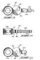
- a guide sleeve 46 which includes an arcuate base 48 (see Figure 4) disposed between the reinforcement 26 and cell 10 and that also includes a section tubular 50 threaded internal surface attached to the base 48 by a neck 52 in the shape of a small plate arranged longitudinally along the cell 10 and projecting radially from it.
- This neck 52 is preferably screwed to the arcuate base 48 to allow guide sleeves 46 and, more particularly, to their tubular sections 50 and their necks 52 to be removed from the joint J.
- a guide adapter 54 is screwed to its lower end 56 with the help of a net left in the threaded tube 50 of each of two guide sleeves 46.
- the upper end of each guide adapter 54 includes a tubular cylindrical section 58 providing a net in its central opening.
- a guide rod 60 of shape cylindrical is slid opposite each of the reinforcements 26 in the guide rings 44 respective for the installation of the seal J in the expansion joint E.
- the ends lower guide rods 60 provide each a threaded section that screws into the section tubular cylindrical 58 of a guide adapter 54 respective.
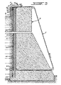
- FIGS 5 to 7 illustrate a method to produce an expansion joint E in a dam-weight B, this expansion joint E being consisting mainly of a vertical fault or cut created following several steps across the dam B and practically all the way up and by positioning the seal J in the cut in the B dam
- the first is to drill holes in the dam which are completely vertical to using a vertical drilling rig controlled by the Applicant and which makes part of public knowledge.
- the second type digging corresponds to a borehole whose verticality is ensured by a guiding device connected to two vertically drilled holes that are maybe the result of vertical drilling controlled.
- This guiding device represents a another aspect of the present invention which will be described in detail later in the text with reference to Figures 8 to 15.
- the third type of digging uses a diamond cable C which represents a modification of similar cables used in quarries for various sawing activities. A such diamond wire C creates a break in the dam B of constant width (10 to 15 millimeters width), while drilling done following the first two types of digging briefly described above produce circular holes that overlap in order to form in the dam B a continuous cut but whose width varies.
- a template 84 is used to ensure inter alia the orientation of the dam B cutoff for produce the expansion joint E. Indeed, the template 84 allows the alignment of the holes forming the cutting the expansion joint E following a pre-established orientation.
- the first four holes are drilled, that is to say the holes 62, 64, 66 and 68.
- These holes that are dug using the device controlled vertical drilling are practiced in the dam B to ride on both sides the two holes 70 and 74 provided to receive the seals J.
- the holes 62, 64, 66 and 68 being perfectly vertical, we now use a drilling device mounted to the device guidance for overlapping and parallel drilling between them to dig the circular holes 70, 72, 74 and 76.
- the seal J is down into hole 70 using a crane or another which clings to two of the holes 19 of the mouthpiece top 16 of the seal J.
- the semi-spherical shape of the bottom nozzle 20 attends to inserting and lowering the seal J in the hole 70 whose progression in the hole 70 is under the same weight of the seal J.
- the guide rods 60 are inserted into the holes 62 and 64 which overlap on both sides the hole 70 receiving the seal J to guide the seal in its hole 70.
- the reinforcements 26 are positioned vis-à-vis the cut and thus form an obstacle to the deformation of the cell 10 in direction and partially to inside the holes 62 and 64 that could flow the effect of radial pressure to the outside in the cell 10.
- each reinforcement 26 The vertical edges of the each reinforcement 26 are leaning against the wall internal hole 70 on both sides of the opening communicating with holes 62 and 64 due to overlapping holes.
- the seal J seal could be installed in the hole 70 using only one of the guide rods 60.
- joint J can be installed from so that the lower end 20 sits at the bottom of the hole 70, as shown in FIG. 5A.
- the lower nozzle 20 can be positioned way to be suspended in the hole 70 (see figure 5) to leave a game in hole 70.
- the seal J is then attached to the dam B by connecting the two other holes 19 of the upper nozzle 16 to the concrete of the upper end of the hole 70.
- the seal J is then filled with a non liquid frost (at least in regions subject to low temperatures); such as antifreeze that does not attack the seal rubber J ("Prestone TM").
- Pressurized gas can then be introduced into the cell 10 to obtain the desired pressure therein.
- the cap 32 is closed so as to seal the cell 10 to maintain it under pressure.
- the guide rods 60 are then unscrewed from the guide adapters 54 of the rod and slidably removed from the guide rings 44 and the hole 74. It is noted that the insertion of the seal J into the hole 70 under the effect Its own weight is facilitated if the cell 10 is gradually filled with its liquid.
- the walls of the hole 70 may be lubricated for example by means of bentonite or a polymer-based fluid.
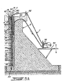
- a hole horizontal can be drilled to join the front from dam B to hole 68 and thus allow the cable diamond C to go around the dam B as it is see Figure 5.
- Other arrangements may be used for the diamond cable route, for example, in cases where the horizontal hole should join a narrow cut. In this case and in others, one can use a another method of using diamond wire C, as shown in Figure 5A.
- the diamond wire C is guided by a movable pulley that is mounted, by example, to a hydraulic cylinder 90 and by guide pulleys 92.
- the movable pulley 88 is inserted at a certain depth (10 feet, for example) in the holes adjacent to the cut you want using the diamond wire C.
- One of the two sections of the diamond wire that come out of these holes is guided by the pulley 92 located above dam B, while the other section of cable leans on top of the dam so there press down and cut the dam gradually down.
- the cutoff 82 is almost made at the pulley mobile 88, the diamond wire C has no longer any force on concrete and can not, therefore, continue to cut the dam B.
- Scaffolding mobile 94 can be used to ensure in any time a proper sawing effort on the dam B.
- the reinforcements 26 are dimensioned in length so that they extend towards the down to at least the lower extremities of holes 62 and 64 adjacent to the hole 70 in which locates the seal J.
- the second joint J can used to readjust the first seal J in his hole 70.
- cell 10 of the first seal J may have become slightly twisted in its hole 70.
- Figure 1A illustrates another lower end of the seal J. More particularly, a pulley 96 is mounted to rotation in the lower nozzle 20, and a cable 98 is engaged around the pulley 96 and then goes back vertically on both sides of cell 10. The pulley 96 and the cable 98 replace the rods of 60 guidance used when installing the seal J. The cable 98 passes through the guide rings 44 and spring over the dam B. The seal J went down into the hole 70 being suspended by the cable 98. A Once the installation is complete, the 98 cable can be removed by pulling on one of its ends, or he can be left in place in hole 70 for the possible future readjustment of the J joint or for its replacement. If the cable 98 is removed from the joint J, the subsequent withdrawal of the latter of its hole 70 shall be made using the guide rods 60.
- the guiding device according to the present invention for overlapping and parallel drilling can take many forms depending on the position of the hole that needs to be dug out to the two holes already drilled and whose verticality is established.
- the guiding device ensures the link using pads between a guide sliding in one or more existing holes and a trepan. This allows a parallel hole to be drilled one or those existing. By repeating the same operations, a break can be achieved.
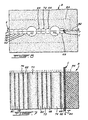
- the guides have appropriate shapes and dimensions to slide in the existing hole or holes. Through For example, in Figure 8, we drill the hole 72 located between holes 64 and 66 already drilled at using vertical drilling rig controlled and which will serve as a guide.
- the guiding device will be type "G-F-G", where "G” indicates a guide and “F” indicates A drilling; therefore, “G-F-G” indicates drilling a hole between two existing and vertical holes that serve as a guide to ensure verticality of the new hole and to ensure that the three holes have longitudinal axes located in the same vertical plane.
- the guiding device required to drill hole 72 using as a guide the holes 64 and 66 will be the type "G4-F4-G4", where the figures indicate the diameters of the guide holes and the hole to be drilled.
- the two devices of "G4-F4-G4" which are each identified by the reference number 100 are arranged remotely vertical one above the other and are connected by adjustment rods 102 which are screwed to guiding devices 100 so as to allow their adjustment so that the two guiding devices 100 are parallel to each other.
- a device drilling usually indicated by F went up to rotation to the guiding devices 100 using pads 104 to ensure the devices of 100 guiding a movement purely in translation down along the guide holes 64 and 66 then that the drill rig F moves down while turning on himself to dig the hole 72.
- the drilling device F comprises the parts following conventional methods: a train of rods 106, a reamer sleeve 108, a corer 110 and a coring ring 112.
- One of the rods 102 is provided with flexible guides 114 to prevent jamming of the drilling device F.
- Each flexible guide 114 is in the form of a disk horizontal diameter slightly smaller than hole diameter 66 of FIG.
- Figure 9 illustrates the device of guide 100 which includes the bushing assembly forced 104, a guide disc 116 of diameter nearly identical to the guide hole 64 and provided with a opening 118 for receiving the adjustment rod 102, and an extension 120 for the guide hole 66 and also provided with an opening 122 for receive the other adjustment rod 102.
- One piece any connection 117 joins the pad forced assembly 104 to the guide disc 116.
- This connecting piece 117 has a slightly width less than the overlap of holes 64 and 72. Similar way, the width of the extension 120 corresponds to the overlap of holes 72 and 66.
- the guide disc 116 and the extension 120 ensures the vertical descent of the drilling device F, preventing the latter from following a movement helical that drilling activity would encourage.
- the guide disc 116 ensures the verticality of the new hole drilled by the drilling device F while the extension 120 ensures that the three holes are aligned longitudinal coplanar.
- the extension 120 and the flexible guide 114 allow a game between the holes that are obviously not perfectly parallel; in addition, they prevent the movement of spiral of the drilling device F.
- the rubber of the flexible guide 114 prevents jamming of the device drilling F since it behaves similar to that of a chimney brush as it follows the walls of the hole while deflecting on its periphery against the direction of movement of the drilling device F.
- extension 120 by a second guide disc identical to the guide disc 116 (and, consequently, in diameter similar to Guide Hole 66) would provide the guiding device 100 a too rigid structure, which would cause the breakage of the latter and / or perhaps that of the drilling rig F.
- widths of the connecting piece 117 and the extension 120 ensure alignment of holes 64, 66 and 72 since they offer little play compared to the width of their respective overlap. Also, replacing the guide disc 116 with an extension similar to the extension 120 would make sure that the drilling device F would exert too much pressure on the edges defined by the overlaps of the holes concerned.
- Figures 10 and 11 illustrate a guidance device 123 of the type "G4-F8-G4" which is used to drill a hole 8 inches in diameter between two pilot holes 4 inches in diameter each.
- This type of device is used to drill holes 70 and 74 (which receive the joints J) between the holes 62 and 64, and 66 and 68, respectively.
- an adapter 124 as shown in Figure 12 is used to rotate the guide device "G4-F8-G4" to the drilling device F.
- the adapter 124 includes among others a pad 126 and a ring restraint 128.
- Figures 13 and 14 illustrate a guidance device 130 of the type "F4-G4-G8" which is when the two pilot holes are overlap, to drill a third vertical hole overlapping one of the two guide holes.
- the guiding device 130 is used to drill the hole 76 of Figures 5 and 6 which has 4 inches of diameter, the guide holes being holes 62 and 70 having respectively 4 and 8 inches in diameter.
- Figure 15 illustrates a device for guidance 132 of the type "F4-G4-G4" which is also used when both guide holes overlap to drill a third vertical hole overlapping one of the two guide holes.
- the guiding device 132 is used to drill holes 78 and 80 of Figures 5 and 6 each having 4 inches in diameter.
- the guide holes for the hole to be drilled 78 are the holes 76 and 62, while for the hole 80, the guide holes are holes 78 and 76, all those holes each having 4 inches in diameter.
- the seal will absorb or compensate for the relative movements of various sections of the dam. Indeed, for correct anomalies in the behavior of dams, it is sometimes necessary to practice cuts.
- This device ensures the sealing cuts and following the subsequent deformations of the dams.
- the device is composed of two cells made of elastic materials reinforced, inserted in pre-drilled holes in the plan of the cut. For the tensioning of cells, these are filled with a liquid (no gel if required) and additional pressure gas is maintained.
- the guidance device for drilling overlap and parallels between them was developed for cell installation sealing, during cuts of dams. However, the same device can be used to all other cuts by drilling.
- the seal J following the present invention can also be used in other applications involving works in concrete and perhaps in works made of other rigid materials, such as stone, metal structures, etc.
- the J joint could be implanted in oil recovery ponds undergoing stress due, for example, to the ground in order to solve the environmental problems that can be caused by an oil leak in the ground.
- the cell could be built of a synthetic material, or rubber cell could be coated with a protective coating.
- the seal J could also be used for repair work, temporary or permanent.
- cement grout or other that has been injected leaks frequently by the cut itself downstream side and on the upstream side before it can solidify. Therefore, one installs easily downstream of the cut a temporary clogging structure for prevent the grout from escaping.
- a recovery basin for example, could be boxed so as to define cuts on two of its walls. During the formwork, a hole would be provided on each of the cuts. A cardboard tube could be installed in each hole and be subsequently removed before installing the seal sealing. The installation of seals in the holes of each of the expansion joints would seal the pelvis and allow it to move to over the years without breaking.
Landscapes
- Engineering & Computer Science (AREA)
- Geology (AREA)
- Life Sciences & Earth Sciences (AREA)
- Mining & Mineral Resources (AREA)
- Environmental & Geological Engineering (AREA)
- Geochemistry & Mineralogy (AREA)
- Fluid Mechanics (AREA)
- General Life Sciences & Earth Sciences (AREA)
- Physics & Mathematics (AREA)
- General Engineering & Computer Science (AREA)
- Mechanical Engineering (AREA)
- Structural Engineering (AREA)
- Ocean & Marine Engineering (AREA)
- Civil Engineering (AREA)
- Working Measures On Existing Buildindgs (AREA)
- Underground Structures, Protecting, Testing And Restoring Foundations (AREA)
- Building Environments (AREA)
Claims (29)
- Dichtungsvorrichtung (J) zum Abdichten einer in einem Betonerzeugnis (B) ausgebildeten Öffnung, umfassend eine Zelle (10), die aus einem elastischen Werkstoff gefertigt ist und wenigstens einen röhrenförmigen Abschnitt enthält, welche Zelle (10) an ihren oberen (12) und unteren (13) Enden jeweils mit einem oberen starren Ansatz (16) und einem unteren starren Ansatz (20) versehen ist, wobei die untere Fläche des unteren Ansatzes (20) so geformt ist, dass sie das Einfügen der Dichtungsvorrichtung (J) in ein auf der Öffnung ausgebildetes Loch (70) erleichtert, gering dehnbare Mittel (36), die zwischen den oberen und unteren Ansätzen (16, 20) angebracht sind, um das Ausdehnen in Längsrichtung der Zelle (10) zu verhindern, welche Zelle (10) Verstärkungsmittel (26) einschließt, die voneinander beabstandet sind und gegenüber der Öffnung angeordnet sind, um die Verformung der Zelle (10) in der Öffnung zu verhindern, wobei ein kontinuierlicher Umfangsraum auf der Zelle (10) zwischen den unteren Enden der Verstärkungsmittel (26) und dem oberen Ende des unteren Ansatzes (20) definiert ist, und Mittel (44, 46, 54, 60; 44, 96, 98) um die Positionierung und die Einrichtung der Dichtungsvorrichtung (J) zu ermöglichen.
- Dichtungsvorrichtung (J) nach Anspruch 1, bei welcher die oberen und unteren Ansätze (16, 20) jeweils wenigstens einen zylindrischen Abschnitt aufweisen, wobei die einen Zylinder formende Zelle (10) an ihren oberen und unteren Enden (12, 14) die jeweiligen zylindrischen Abschnitte der oberen und unteren Ansätze fest überdeckt (16, 20).
- Dichtungsvorrichtung (J) nach Anspruch 2, bei welcher die zylindrischen Abschnitte der oberen und unteren Ansätze (16, 20) jeweils Haltearretierungen auf ihrem jeweiligen Umfang bilden (18, 22), welche zu deren Fügung jeweils in Eingriff mit den oberen und unteren Enden (12, 14) der zylindrischen Zelle (10) sind, wobei Haltebünde (28, 24) um die oberen und unteren Enden (12, 14) der Zelle (10) montiert sind, um die Fügung zu verstärken.
- Dichtungsvorrichtung (J) nach Anspruch 2, bei welcher der untere Ansatz (20) einen halb-sphärischen Abschnitt am unteren Ende seines zylindrischen Abschnitts umfasst.
- Dichtungsvorrichtung (J) nach Anspruch 1, bei welcher die wenig dehnbaren Mittel wenigstens ein in der Zelle (10) gespanntes Kabel (36) umfassen, wobei die Enden von jedem Kabel (36) an ihrem jeweiligen Ansatz mithilfe von Befestigungsmitteln (38, 40, 42) befestigt sind.
- Dichtungsvorrichtung (J) nach Anspruch 5, bei welcher die Befestigungsmittel (38, 40, 42) Augbolzen (38, 40) umfassen.
- Dichtungsvorrichtung (J) nach Anspruch 2, bei welcher der obere Ansatz (16) einen im Innern des zylindrischen Abschnitts montierten Haltering (30) umfasst, welcher Haltering (30) eine, einen Stopfen (32) aufnehmende mittige Gewindeöffnung ausbildet, welcher Stopfen (32) eine Öffnung (34) enthält, die mit einem Anschlussstutzen (33) verbunden ist, der ein Ventil (35) umfasst, um den Eintritt von wenigstens einem Fluid in die Zelle (10) zu ermöglichen und das Aufrechterhalten des gewünschten Fluiddrucks in der Zelle (10) zu gewährleisten.
- Dichtungsvorrichtung (J) nach Anspruch 1, bei welcher die Zelle (10) aus einem gummiartigen Material gefertigt ist.
- Dichtungsvorrichtung (J) nach Anspruch 1, bei welcher der obere Ansatz (16) Mittel (19) für die Handhabung der Dichtungsvorrichtung (J) und für ihre Befestigung an dem Erzeugnis umfasst.
- Dichtungsvorrichtung (J) nach Anspruch 1, bei welcher die Verstärkungsmittel (26) zwei Längsverstärkungen (26) umfassen, die außerhalb, beiderseitig der Zelle (10) angeordnet sind.
- Dichtungsvorrichtung (J) nach Anspruch 10, bei welcher die Verstärkungen (26) aus einem starren Werkstoff gefertigt sind und auf die Zelle (10) geklebt sind.
- Dichtungsvorrichtung (J) nach Anspruch 10, bei welcher die Mittel (44, 96, 98) zum Ermöglichen der Positionierung und der Einrichtung der Dichtungsvorrichtung (J) Führungsringe (44), die außerhalb, längs jeder der Verstärkungen (26) angeordnet sind und in die Öffnung eingefügt sind, eine vertikal am unteren Ende des unteren Ansatzes (20) montierte Seilrolle (96), und ein in die Seilrolle (96) greifendes Kabel (98), das beiderseits der Zelle (10) wieder aufsteigt und hierbei durch die jeweiligen Führungsringe (44) der beiden Verstärkungen (26) hindurchtritt, umfassen.
- Dichtungsvorrichtung (J) nach Anspruch 12, bei welcher die Führungsringe (44) jeweils eine gebogene Basis aufWeisen, die zwischen der Zelle (10) und einer jeweiligen Verstärkung (26) angeordnet ist.
- Dichtungsvorrichtung (J) nach Anspruch 10, bei welcher die Vorrichtung zum Einrichten (44, 46, 54, 60) Führungsringe (44), die längs jeder der Verstärkungen (26) angeordnet sind und in die Öffnung eingefügt sind, wobei wenigstens eine Führungsstange (60) durch die jeweiligen Führungsringe (44) einer der beiden Verstärkungen (26) hindurchtritt und ein unteres Gewindeende enthält, eine Führungsmuffe (46), die am unteren Ende der Verstärkung (26) angebracht ist und eine mittige Gewindeöffnung ausbildet um eine jeweilige Führungsstange (60) aufzunehmen, umfasst.
- Dichtungsvorrichtung (J) nach Anspruch 14, bei welcher die Führungsringe (44) jeweils eine gebogene Basis aufweisen, die zwischen der Zelle (10) und einer jeweiligen Verstärkung (26) angeordnet ist, wobei eine Führungsstange (60) für die Führungsringe (44) jeder der beiden Verstärkungen (26) vorgesehen ist.
- Verfahren zum Einrichten einer Dehnungsfuge (E) in einem Betonerzeugnis (B) mithilfe einer Dichtungsvorrichtung (J), die eine rohrförmige und elastische Zelle (10), die an ihren oberen und unteren Enden (12, 14) jeweils mit einem starren oberen Ansatz (16) und einem starren unteren Ansatz (20) versehen ist, wobei die untere Fläche des unteren Ansatzes (20) derart geformt ist, dass das Einfügen der Dichtungsvorrichtung (J) in das Betonerzeugnis (B) erleichtert ist, gering dehnbare Mittel (36), die zwischen den oberen und unteren Ansätzen (16, 20) angebracht sind, umfasst, welche Zelle (10) Verstärkungsmittel (26) einschließt, die voneinander beabstandet sind, wobei ein kontinuierlicher Umfangsraum auf der Zelle (10) zwischen den unteren Enden der Verstärkungsmittel (26) und dem oberen Ende des unteren Ansatzes (20) definiert ist, welches Verfahren die folgenden Schritte einschließt:a) Bohren eines ersten Lochs (70) in das Erzeugnis, welches bestimmt ist, die Dichtungsvorrichtung (J) aufzunehmen;b) Einrichten der Dichtungsvorrichtung (J) in dem ersten Loch (70), wobei die Verstärkungsmittel (26) in der Strömungsrichtung positioniert sind;c) Füllen unter erforderlichem Druck der Zelle (10) mithilfe wenigstens eines geeigneten Fluids; undd) Fertigstellen der Dehnungsfuge (E) durch die Abtrennung des Erzeugnis in der Strömungsrichtung und gegenüber den Verstärkungsmitteln (26), wobei die Abtrennung mit dem ersten Loch (70) und somit mit der Dichtungsvorrichtung (J) kommuniziert und sich in eine Tiefe verlängert, die im wesentlichen den unteren Enden der Verstärkungsmittel (26) entspricht, derart, dass sich der Abschnitt der Zelle (10), der sich zwischen den Verstärkungsmitteln (26) und dem unteren Ansatz (20) befindet, auf seinem Umfang den Wänden des ersten Lochs (70) anschmiegt.
- Verfahren nach Anspruch 16, bei welchem vor dem Schritt b) ein zweites und ein drittes Loch (62, 64) mit Überlappung auf beiden Seiten des ersten Lochs (70) gebohrt werden, um die Schritte b) und d) zu erleichtern.
- Verfahren nach Anspruch 17, bei welchem vor dem Schritt d) ein viertes Loch (74) gebohrt wird, wobei dieses vierte Loch (74) bestimmt ist, eine zweite Dichtungsvorrichtung (J) aufzunehmen, die ähnlich zu jener es ersten Lochs (70) ist, und bei welchem, in dem Schritt d) die Abtrennung zur Fertigstellung der Dehnungsfuge (E) gleichermaßen das vierte Loch (74) erreicht.
- Verfahren nach Anspruch 18, bei welchem eine zweite Dichtungsvorrichtung (J) in dem vierten Loch (74) eingerichtet wird, und anschließend mit einem geeigneten Fluid gefüllt wird.
- Verfahren nach Anspruch 19, bei welchem die zweite Dichtungsvorrichtung (J) mithilfe wenigstens eines geeigneten Fluids unter geeignetem Druck gefüllt wird.
- Verfahren nach Anspruch 17, bei welchem die Dichtungsvorrichtung (J) eine Vorrichtung zur Einrichtung (44, 96, 98), welche außerhalb, längs jedem der Verstärkungsmittel (26) angeordnete Führungsringe (44) enthält, eine Seilrolle (96), welche am unteren Ende des unteren Ansatzes (20) vertikal angebracht ist, und ein Kabel (98), welches mit der Seilrolle (96) in Eingriff ist und beiderseits der Zelle (10) wieder aufsteigt und hierbei durch die jeweiligen Führungsringe (44) der Verstärkungsmittel (26) hindurchtritt, umfasst, welches Verfahren in Schritt b) das Einfügen der Führungsringe (44) in die zweiten und dritten Löcher (62, 64) umfasst.
- Verfahren nach Anspruch 17, bei welchem die Dichtungsvorrichtung (J) eine Vorrichtung zur Einrichtung (44, 46, 54, 60), welche außerhalb, längs jedem der Verstärkungsmittel (26) angeordnete Führungsringe (44) enthält, wenigstens eine Führungsstange (60), welche durch die jeweiligen Führungsringe (44) eines Verstärkungsmittels (26) hindurchtritt und ein unteres Gewindeende enthält, eine Führungsmuffe (46), die an dem unteren Ende des Verstärkungsmittels (26) angebracht ist und eine mittige Gewindeöffnung ausbildet, die eine jeweilige Führungstange (60) aufnimmt, umfasst, welches Verfahren in Schritt b) das Einfügen der Führungsstange (60) und deren Führungsringe (44) in eines der zweiten und dritten Löcher (62, 64), die Befestigung der Dichtungsvorrichtung (J) am Erzeugnis, dann das Abschrauben der Führungsstange (60) von der Führungsmuffe (46), und schließlich das Herausziehen der Führungsstange (60) aus ihrem Loch (62, 64) umfasst.
- Verfahren nach Anspruch 22, bei welchem eine Führungsstange (60) für jedes der zweiten und dritten Löcher (62, 64) verwendet wird, wobei jede Führungsstange (60) zu einem der Verstärkungsmittel (26) gehört.
- Verfahren zum Nachstellen einer Dichtungsvorrichtung (J) einer in einen Betonstaudamm (B) geschnittenen Dehnungsfuge (E) welche Dichtungsvorrichtung (J) eine rohrförmige und elastische Zelle (10), die an ihren oberen und unteren Enden (12, 14) jeweils mit einem starren oberen Ansatz (16) und einem starren unteren Ansatz (20) versehen ist, wobei die untere Fläche des unteren Ansatzes (20) derart geformt ist, dass sie das Einfügen der Dichtungsvorrichtung (J) in den Staudamm erleichtert, gering dehnbare Mittel (36), die zwischen den oberen und unteren Ansätzen (16, 20) angebracht sind, umfasst, welche Zelle (10) Verstärkungsmittel (26) einschließt, die voneinander beabstandet sind, wobei ein kontinuierlicher Umfangsraum auf der Zelle (10) zwischen den unteren Enden der Verstärkungsmittel (26) und dem oberen Ende des unteren Ansatzes (20) definiert ist, welche Dichtungsvorrichtung (J) in einem in dem Betonstaudamm (B) auf der Dehnungsfuge (E) ausgebildeten ersten Loch (70) eingerichtet ist, ihre Verstärkungsmittel (26) in der Strömungsrichtung von Wasser positioniert sind, die Zelle (10) mithilfe wenigstens eines geeigneten Fluids unter Druck gesetzt ist, eine zweite Dichtungsvorrichtung (J), die zur Dichtungsvorrichtung (J) des ersten Lochs (70) ähnlich ist, in einem, gleichermaßen auf der Dehnungsfuge (E) ausgebildeten, zweiten Loch (74) eingerichtet ist, welches Verfahren die folgenden Schritte umfasst:a) unter Spannung setzen der zweiten Dichtungsvorrichtung (J) unter dem erforderlichen Druck mithilfe wenigstens eines geeigneten Fluids;b) wenigstens teilweise auf Außendruck bringen der Dichtungsvorrichtung (J) des ersten Lochs (70), um ihre Haftung an den Wänden des ersten Lochs (70) aufzuheben, und ihr zu ermöglichen, ihre Position in dem ersten Loch (70) wieder einzunehmen; undc) unter Spannung setzen der Dichtungsvorrichtung (J) des ersten Lochs (70).
- Verfahren nach Anspruch 24, bei welchem das Einrichten und das unter Spannung setzen der zweiten Dichtungsvorrichtung (J) das Bohren eines zweiten Lochs (74) auf der Dehnungsfuge (E), welches bestimmt ist, die zweite Dichtungsvorrichtung (J) aufzunehmen, und die Füllung der zweiten Dichtungsvorrichtung (J) unter dem erforderlichen Druck mithilfe des geeigneten Fluids umfasst.
- Verfahren zum Nachstellen nach Anspruch 24, bei welchem der Schritt d) darin besteht, die zweite Dichtungsvorrichtung (J) auf Außendruck zu bringen.
- Verfahren zum Ersetzen einer Dichtungsvorrichtung (J) einer in einen Betonstaudamm (B) geschnittenen Dehnungsfuge (E), welche Dichtungsvorrichtung (J) eine rohrförmige und elastische Zelle (10), die an ihren oberen und unteren Enden (12, 14) jeweils mit einem starren oberen Ansatz (16) und einem starren unteren Ansatz (20) versehen ist, wobei die untere Fläche des unteren Ansatzes (20) derart geformt ist, dass sie das Einfügen der Dichtungsvorrichtung (J) in den Staudamm erleichtert, gering dehnbare Mittel (36), die zwischen den oberen und unteren Ansätzen (16, 20) angebracht sind, umfasst, welche Zelle (10) Verstärkungsmittel (26) einschließt, die voneinander beabstandet sind, wobei ein kontinuierlicher Umfangsraum auf der Zelle (10) zwischen den unteren Enden der Verstärkungsmittel (26) und dem oberen Ende des unteren Ansatzes (20) definiert ist, welche Dichtungsvorrichtung (J) in einem in dem Betonstaudamm (B) auf der Dehnungsfuge (E) ausgebildeten ersten Loch (70) eingerichtet ist, ihre Verstärkungsmittel (26) in der Strömungsrichtung von Wasser positioniert sind, die Zelle (10) mithilfe wenigstens eines geeigneten Fluids unter Druck gesetzt ist, eine zweite Dichtungsvorrichtung (J), die zur Dichtungsvorrichtung (J) des ersten Lochs (70) ähnlich ist, in einem, gleichermaßen auf der Dehnungsfuge (E) ausgebildeten, zweiten Loch (74) eingerichtet ist, welches Verfahren die folgenden Schritte umfasst:a) unter Spannung setzen der zweiten Dichtungsvorrichtung (J) unter dem erforderlichen Druck mithilfe wenigstens eines geeigneten Fluids;b) auf Außendruck bringen der Dichtungsvorrichtung (J) des ersten Lochs (70);c) Entleerung des in der Dichtungsvorrichtung (J) des ersten Lochs (70) enthaltenen Fluids und ihr Herausziehen aus dem ersten Loch (70); undd) Einrichten einer neuen Dichtungsvorrichtung (J) in dem ersten Loch (70), ihre darauffolgende Füllung mithilfe wenigstens eines geeigneten Fluids, und unter Spannung setzen der neuen Dichtungsvorrichtung (J) des ersten Lochs (70).
- Verfahren nach Anspruch 27, bei welchem die Einrichtung und das unter Spannung setzen der zweiten Dichtungsvorrichtung (J) das Bohren eines zweiten Lochs (74) auf der Dehnungsfuge (E), welches bestimmt ist, die zweite Dichtungsvorrichtung (J) aufzunehmen, und die Füllung der zweiten Dichtungsvorrichtung (J) unter dem erforderlichen Druck mithilfe des geeigneten Fluids umfasst.
- Verfahren zum Ersetzen nach Anspruch 27, bei welchem der Schritt e) darin besteht, die zweite Dichtungsvorrichtung (J) auf Außendruck zu bringen.
Applications Claiming Priority (3)
| Application Number | Priority Date | Filing Date | Title |
|---|---|---|---|
| CA002064429A CA2064429C (fr) | 1992-03-30 | 1992-03-30 | Dispositif d'etancheite pour joints d'expansion coupes dans les barrages |
| CA2064429 | 1992-03-30 | ||
| PCT/CA1993/000126 WO1993020288A2 (fr) | 1992-03-30 | 1993-03-26 | Dispositif d'etancheite pour scellement de joints d'expansion coupes dans des barrages en beton et procede d'installation du dispositif |
Publications (2)
| Publication Number | Publication Date |
|---|---|
| EP0633965A1 EP0633965A1 (de) | 1995-01-18 |
| EP0633965B1 true EP0633965B1 (de) | 2003-06-11 |
Family
ID=4149519
Family Applications (1)
| Application Number | Title | Priority Date | Filing Date |
|---|---|---|---|
| EP93907701A Expired - Lifetime EP0633965B1 (de) | 1992-03-30 | 1993-03-26 | Dichtungsvorrichtung für Abdichtung von Dehnungsfugen in Betonstaudämmen und Einrichtungsverfahren derselben |
Country Status (7)
| Country | Link |
|---|---|
| US (2) | US5449248A (de) |
| EP (1) | EP0633965B1 (de) |
| JP (1) | JPH07508568A (de) |
| AU (1) | AU3882993A (de) |
| BR (1) | BR9306182A (de) |
| CA (1) | CA2064429C (de) |
| WO (1) | WO1993020288A2 (de) |
Cited By (1)
| Publication number | Priority date | Publication date | Assignee | Title |
|---|---|---|---|---|
| CN101429756B (zh) * | 2008-01-13 | 2012-07-04 | 张明军 | 混凝土面板接缝嵌填的柔性填料的夯实方法 |
Families Citing this family (9)
| Publication number | Priority date | Publication date | Assignee | Title |
|---|---|---|---|---|
| CA2064429C (fr) * | 1992-03-30 | 1999-06-22 | Peter Szita | Dispositif d'etancheite pour joints d'expansion coupes dans les barrages |
| US5570934A (en) * | 1995-03-16 | 1996-11-05 | Hydro-Quebec | Traction boring device using multiple trepans for producing large cuts in concrete works and the like and method of producing cuts |
| US20040234340A1 (en) * | 2003-05-20 | 2004-11-25 | Cho Yong Min | Mobile levee system |
| US20100080653A1 (en) * | 2008-09-26 | 2010-04-01 | Lewis Thomas H | Pavement Seal, Installation Machine And Method Of Installation |
| US8100602B2 (en) * | 2009-05-29 | 2012-01-24 | The D. S. Brown Company | Apparatus for installing elongate seal strips |
| CN102677676B (zh) * | 2012-06-04 | 2014-09-24 | 中国电建集团西北勘测设计研究院有限公司 | 常态混凝土拱坝接缝灌浆槽管结合排气方法 |
| CN103290808A (zh) * | 2012-08-31 | 2013-09-11 | 中国长江三峡集团公司 | 接缝灌浆系统中排气槽封口的改进新方法 |
| CN113005996B (zh) * | 2021-02-25 | 2022-09-27 | 中国电建集团北京勘测设计研究院有限公司 | 一种水利水电工程临时生态流量管的封堵结构 |
| CN117245122B (zh) * | 2023-11-20 | 2024-01-19 | 成都天科航空制造股份有限公司 | 一种用于航空销轴上钻止动销孔的钻孔工装及钻孔方法 |
Family Cites Families (15)
| Publication number | Priority date | Publication date | Assignee | Title |
|---|---|---|---|---|
| FR22446E (fr) * | 1918-04-22 | 1921-07-12 | Frederic Guillierme | Machine pour le creusage de trous de mine |
| US1628933A (en) * | 1925-11-11 | 1927-05-17 | Arthur E Troiel | Method of grouting |
| US1719003A (en) * | 1927-01-13 | 1929-07-02 | Gardner Denver Co | Anchor for drill-steel guides |
| US2341322A (en) * | 1942-01-14 | 1944-02-08 | Sullivan Machinery Co | Drill guide |
| US2368511A (en) * | 1942-08-06 | 1945-01-30 | Ingersoll Rand Co | Guide for drill steels |
| CH424850A (fr) * | 1963-07-05 | 1966-11-30 | Ingersoll Rand Co | Procédé pour le percement de galeries et appareil pour sa mise en oeuvre |
| FR1429417A (fr) * | 1965-01-12 | 1966-02-25 | Système de pointage en direction de foreuse, ou autre appareil, en exploitation desmines ou travaux publics | |
| US3342033A (en) * | 1965-04-08 | 1967-09-19 | Layne Texas Company Inc | Method of providing a sealed joint employing a flexible bag |
| SE365022B (de) * | 1971-08-23 | 1974-03-11 | G Wibom | |
| AU456875B2 (en) * | 1972-08-16 | 1975-01-16 | Duane Goettl Adam | An elongated inflatable sealand containment devices for use in sealing joints between perpendicularly disposed structural members and coplanar structural members |
| GB1552636A (en) * | 1975-05-29 | 1979-09-19 | Wibom G H O | Drilling machine |
| US4268192A (en) * | 1978-09-11 | 1981-05-19 | Raymond International Builders, Inc. | Concrete wall construction |
| JPH0643690B2 (ja) * | 1985-01-29 | 1994-06-08 | 株式会社ブリヂストン | 築堤ブロツク用目地材 |
| US4655638A (en) * | 1986-06-12 | 1987-04-07 | Gelco Grouting Service | Waterstop for monolith joints and method |
| CA2064429C (fr) * | 1992-03-30 | 1999-06-22 | Peter Szita | Dispositif d'etancheite pour joints d'expansion coupes dans les barrages |
-
1992
- 1992-03-30 CA CA002064429A patent/CA2064429C/fr not_active Expired - Fee Related
-
1993
- 1993-03-15 US US08/031,465 patent/US5449248A/en not_active Expired - Fee Related
- 1993-03-26 AU AU38829/93A patent/AU3882993A/en not_active Abandoned
- 1993-03-26 EP EP93907701A patent/EP0633965B1/de not_active Expired - Lifetime
- 1993-03-26 JP JP5516923A patent/JPH07508568A/ja active Pending
- 1993-03-26 BR BR9306182A patent/BR9306182A/pt not_active Application Discontinuation
- 1993-03-26 WO PCT/CA1993/000126 patent/WO1993020288A2/fr not_active Ceased
-
1995
- 1995-06-07 US US08/479,044 patent/US5735636A/en not_active Expired - Fee Related
Cited By (1)
| Publication number | Priority date | Publication date | Assignee | Title |
|---|---|---|---|---|
| CN101429756B (zh) * | 2008-01-13 | 2012-07-04 | 张明军 | 混凝土面板接缝嵌填的柔性填料的夯实方法 |
Also Published As
| Publication number | Publication date |
|---|---|
| BR9306182A (pt) | 1998-06-23 |
| WO1993020288A3 (fr) | 1994-03-31 |
| WO1993020288A2 (fr) | 1993-10-14 |
| CA2064429A1 (fr) | 1993-10-01 |
| US5449248A (en) | 1995-09-12 |
| CA2064429C (fr) | 1999-06-22 |
| EP0633965A1 (de) | 1995-01-18 |
| AU3882993A (en) | 1993-11-08 |
| US5735636A (en) | 1998-04-07 |
| JPH07508568A (ja) | 1995-09-21 |
Similar Documents
| Publication | Publication Date | Title |
|---|---|---|
| EP1525371B1 (de) | Teleskopführungsleitung für offshore-bohren | |
| EP0020232B1 (de) | Verfahren und Vorrichtung zur Befestigung von Leitungen, wie Pipelines, auf dem Meeresboden | |
| EP0136935B1 (de) | Vorrichtung zum Bohren von und Gewinnen aus einem Multidrain-Bohrloch | |
| FR2588297A1 (fr) | Dispositif pour le forage sous-marin de fondations | |
| EP0265344B1 (de) | Verfahren zum Herstellen eines Pfahls im Boden, sowie Bohrmaschine und Vorrichtung zur Ausführung dieses Verfahrens | |
| EP0574326B1 (de) | Einrichtung, System und Verfahren zum Bohren und Ausrüsten eines seitlichen Bohrloches | |
| EP0633965B1 (de) | Dichtungsvorrichtung für Abdichtung von Dehnungsfugen in Betonstaudämmen und Einrichtungsverfahren derselben | |
| FR2806111A1 (fr) | Appareil de forage en terrain dur | |
| EP0404703A1 (de) | Gründungspfähle, Verfahren, Geräte und Vorrichtungen zur Herstellung dieser Pfähle | |
| FR2521635A1 (fr) | Siege et appareil pour dispositif de suspension de colonne, et procede de completion d'un puits sous-marin | |
| FR2791733A1 (fr) | Procede et dispositif pour la completion de puits pour la production d'hydrocarbures ou analogues | |
| EP0080471A1 (de) | Schwimmende insel, insbesondere bohrinsel, und verfahren zu deren verankerung | |
| EP0828108A1 (de) | Verfahren zum Verbinden von Leitungen | |
| FR2692316A1 (fr) | Système et méthode de forage et d'équipement de forage latéral, application à l'exploitation de gisement pétrolier. | |
| FR2662207A1 (fr) | Dispositif de tubage d'un forage et procede de tubage en resultant. | |
| EP1407085B1 (de) | Verfahren und vorrichtung zur herstellung einer stahlbetonwand im boden | |
| BE1004718A6 (fr) | Procede pour colmater une fuite de fluide sous pression, en particulier de petrole ou de gaz, et equipement pour la mise en oeuvre de ce procede. | |
| EP1270825B1 (de) | Verfahren und Anlage zum Ausgleichen von Grundsenkungen | |
| FR2654487A1 (fr) | Procede et dispositif pour enfouir une conduite dans un sol. | |
| FR2597187A1 (fr) | Procede et dispositif de soutenement provisoire des parois d'une tranchee | |
| FR2534611A1 (fr) | Procede et dispositif pour la realisation d'une paroi moulee en terrain dur | |
| FR2556405A1 (fr) | Appareil et procede pour faire tourner une colonne enroulee dans un puits | |
| EP0288644A1 (de) | Verfahren und Vorrichtung zum provisorischen Abstützen von Grabenwänden | |
| FR2472657A1 (fr) | Dispositif servant a enfoncer des echangeurs de chaleur de forme tubulaire dans le sol | |
| FR2562148A1 (fr) | Fourreau d'injecteur de colonne enroulee pour puits |
Legal Events
| Date | Code | Title | Description |
|---|---|---|---|
| PUAI | Public reference made under article 153(3) epc to a published international application that has entered the european phase |
Free format text: ORIGINAL CODE: 0009012 |
|
| 17P | Request for examination filed |
Effective date: 19941028 |
|
| AK | Designated contracting states |
Kind code of ref document: A1 Designated state(s): ES FR IT SE |
|
| 17Q | First examination report despatched |
Effective date: 19960124 |
|
| GRAG | Despatch of communication of intention to grant |
Free format text: ORIGINAL CODE: EPIDOS AGRA |
|
| GRAG | Despatch of communication of intention to grant |
Free format text: ORIGINAL CODE: EPIDOS AGRA |
|
| GRAH | Despatch of communication of intention to grant a patent |
Free format text: ORIGINAL CODE: EPIDOS IGRA |
|
| GRAH | Despatch of communication of intention to grant a patent |
Free format text: ORIGINAL CODE: EPIDOS IGRA |
|
| GRAA | (expected) grant |
Free format text: ORIGINAL CODE: 0009210 |
|
| AK | Designated contracting states |
Designated state(s): ES FR IT SE |
|
| PG25 | Lapsed in a contracting state [announced via postgrant information from national office to epo] |
Ref country code: IT Free format text: LAPSE BECAUSE OF FAILURE TO SUBMIT A TRANSLATION OF THE DESCRIPTION OR TO PAY THE FEE WITHIN THE PRE;WARNING: LAPSES OF ITALIAN PATENTS WITH EFFECTIVE DATE BEFORE 2007 MAY HAVE OCCURRED AT ANY TIME BEFORE 2007. THE CORRECT EFFECTIVE DATE MAY BE DIFFERENT FROM THE ONE RECORDED.SCRIBED TIME-LIMIT Effective date: 20030611 |
|
| RIC1 | Information provided on ipc code assigned before grant |
Ipc: 7E 21B 19/24 B Ipc: 7E 02B 3/16 A |
|
| PG25 | Lapsed in a contracting state [announced via postgrant information from national office to epo] |
Ref country code: SE Free format text: LAPSE BECAUSE OF FAILURE TO SUBMIT A TRANSLATION OF THE DESCRIPTION OR TO PAY THE FEE WITHIN THE PRESCRIBED TIME-LIMIT Effective date: 20030911 |
|
| PG25 | Lapsed in a contracting state [announced via postgrant information from national office to epo] |
Ref country code: ES Free format text: LAPSE BECAUSE OF FAILURE TO SUBMIT A TRANSLATION OF THE DESCRIPTION OR TO PAY THE FEE WITHIN THE PRESCRIBED TIME-LIMIT Effective date: 20030922 |
|
| PLBE | No opposition filed within time limit |
Free format text: ORIGINAL CODE: 0009261 |
|
| STAA | Information on the status of an ep patent application or granted ep patent |
Free format text: STATUS: NO OPPOSITION FILED WITHIN TIME LIMIT |
|
| 26N | No opposition filed |
Effective date: 20040312 |
|
| PG25 | Lapsed in a contracting state [announced via postgrant information from national office to epo] |
Ref country code: FR Free format text: LAPSE BECAUSE OF NON-PAYMENT OF DUE FEES Effective date: 20041130 |
|
| REG | Reference to a national code |
Ref country code: FR Ref legal event code: ST |