EP0633965B1 - Cut expansion joint sealing device for concrete dams and method for fitting same - Google Patents
Cut expansion joint sealing device for concrete dams and method for fitting same Download PDFInfo
- Publication number
- EP0633965B1 EP0633965B1 EP93907701A EP93907701A EP0633965B1 EP 0633965 B1 EP0633965 B1 EP 0633965B1 EP 93907701 A EP93907701 A EP 93907701A EP 93907701 A EP93907701 A EP 93907701A EP 0633965 B1 EP0633965 B1 EP 0633965B1
- Authority
- EP
- European Patent Office
- Prior art keywords
- sealing device
- cell
- hole
- end member
- expansion joint
- Prior art date
- Legal status (The legal status is an assumption and is not a legal conclusion. Google has not performed a legal analysis and makes no representation as to the accuracy of the status listed.)
- Expired - Lifetime
Links
- 238000007789 sealing Methods 0.000 title claims abstract description 133
- 238000000034 method Methods 0.000 title claims abstract description 41
- 230000002787 reinforcement Effects 0.000 claims abstract description 68
- 239000012530 fluid Substances 0.000 claims abstract description 30
- XLYOFNOQVPJJNP-UHFFFAOYSA-N water Substances O XLYOFNOQVPJJNP-UHFFFAOYSA-N 0.000 claims abstract description 19
- 230000002093 peripheral effect Effects 0.000 claims abstract description 10
- 238000009434 installation Methods 0.000 claims description 33
- 230000003014 reinforcing effect Effects 0.000 claims description 12
- 238000003780 insertion Methods 0.000 claims description 11
- 230000037431 insertion Effects 0.000 claims description 11
- 239000000463 material Substances 0.000 claims description 11
- 238000005520 cutting process Methods 0.000 claims description 6
- 229920001971 elastomer Polymers 0.000 claims description 5
- 239000013013 elastic material Substances 0.000 claims description 3
- 230000008878 coupling Effects 0.000 claims 3
- 238000010168 coupling process Methods 0.000 claims 3
- 238000005859 coupling reaction Methods 0.000 claims 3
- 238000004873 anchoring Methods 0.000 claims 1
- 239000012858 resilient material Substances 0.000 abstract 1
- 238000005553 drilling Methods 0.000 description 39
- 229910003460 diamond Inorganic materials 0.000 description 12
- 239000010432 diamond Substances 0.000 description 12
- 238000010276 construction Methods 0.000 description 9
- 239000004459 forage Substances 0.000 description 6
- 239000007788 liquid Substances 0.000 description 6
- 239000004033 plastic Substances 0.000 description 6
- 230000008439 repair process Effects 0.000 description 6
- 238000011144 upstream manufacturing Methods 0.000 description 6
- 239000011440 grout Substances 0.000 description 5
- 230000001070 adhesive effect Effects 0.000 description 4
- 230000000694 effects Effects 0.000 description 4
- 239000000853 adhesive Substances 0.000 description 3
- 210000003739 neck Anatomy 0.000 description 3
- 239000004568 cement Substances 0.000 description 2
- 210000003141 lower extremity Anatomy 0.000 description 2
- 238000011084 recovery Methods 0.000 description 2
- 229910001220 stainless steel Inorganic materials 0.000 description 2
- 239000010935 stainless steel Substances 0.000 description 2
- 230000008961 swelling Effects 0.000 description 2
- 238000003466 welding Methods 0.000 description 2
- 239000004606 Fillers/Extenders Substances 0.000 description 1
- 235000019738 Limestone Nutrition 0.000 description 1
- 239000004677 Nylon Substances 0.000 description 1
- 241000425571 Trepanes Species 0.000 description 1
- 240000008042 Zea mays Species 0.000 description 1
- 230000005856 abnormality Effects 0.000 description 1
- 230000002528 anti-freeze Effects 0.000 description 1
- 230000003542 behavioural effect Effects 0.000 description 1
- 239000000440 bentonite Substances 0.000 description 1
- 229910000278 bentonite Inorganic materials 0.000 description 1
- SVPXDRXYRYOSEX-UHFFFAOYSA-N bentoquatam Chemical compound O.O=[Si]=O.O=[Al]O[Al]=O SVPXDRXYRYOSEX-UHFFFAOYSA-N 0.000 description 1
- 230000005540 biological transmission Effects 0.000 description 1
- 238000006243 chemical reaction Methods 0.000 description 1
- 238000007796 conventional method Methods 0.000 description 1
- 238000005336 cracking Methods 0.000 description 1
- 230000002950 deficient Effects 0.000 description 1
- 238000006073 displacement reaction Methods 0.000 description 1
- 230000007613 environmental effect Effects 0.000 description 1
- 238000009415 formwork Methods 0.000 description 1
- 230000008014 freezing Effects 0.000 description 1
- 238000007710 freezing Methods 0.000 description 1
- 239000003292 glue Substances 0.000 description 1
- 230000005484 gravity Effects 0.000 description 1
- 230000008595 infiltration Effects 0.000 description 1
- 238000001764 infiltration Methods 0.000 description 1
- 238000002347 injection Methods 0.000 description 1
- 239000007924 injection Substances 0.000 description 1
- 238000005304 joining Methods 0.000 description 1
- 239000006028 limestone Substances 0.000 description 1
- 230000007774 longterm Effects 0.000 description 1
- 239000000314 lubricant Substances 0.000 description 1
- 238000004519 manufacturing process Methods 0.000 description 1
- 239000002184 metal Substances 0.000 description 1
- 238000012986 modification Methods 0.000 description 1
- 230000004048 modification Effects 0.000 description 1
- 229920001778 nylon Polymers 0.000 description 1
- 210000004197 pelvis Anatomy 0.000 description 1
- 229920000642 polymer Polymers 0.000 description 1
- 239000011253 protective coating Substances 0.000 description 1
- 239000011347 resin Substances 0.000 description 1
- 229920005989 resin Polymers 0.000 description 1
- 230000000452 restraining effect Effects 0.000 description 1
- 230000000717 retained effect Effects 0.000 description 1
- 239000004575 stone Substances 0.000 description 1
- 239000000126 substance Substances 0.000 description 1
- 229920003051 synthetic elastomer Polymers 0.000 description 1
- 229920002994 synthetic fiber Polymers 0.000 description 1
- 238000012360 testing method Methods 0.000 description 1
- 238000013519 translation Methods 0.000 description 1
- 210000001364 upper extremity Anatomy 0.000 description 1
- 238000004078 waterproofing Methods 0.000 description 1
Images


Classifications
-
- E—FIXED CONSTRUCTIONS
- E21—EARTH OR ROCK DRILLING; MINING
- E21B—EARTH OR ROCK DRILLING; OBTAINING OIL, GAS, WATER, SOLUBLE OR MELTABLE MATERIALS OR A SLURRY OF MINERALS FROM WELLS
- E21B7/00—Special methods or apparatus for drilling
- E21B7/28—Enlarging drilled holes, e.g. by counterboring
-
- B—PERFORMING OPERATIONS; TRANSPORTING
- B23—MACHINE TOOLS; METAL-WORKING NOT OTHERWISE PROVIDED FOR
- B23B—TURNING; BORING
- B23B47/00—Constructional features of components specially designed for boring or drilling machines; Accessories therefor
- B23B47/28—Drill jigs for workpieces
-
- E—FIXED CONSTRUCTIONS
- E02—HYDRAULIC ENGINEERING; FOUNDATIONS; SOIL SHIFTING
- E02B—HYDRAULIC ENGINEERING
- E02B3/00—Engineering works in connection with control or use of streams, rivers, coasts, or other marine sites; Sealings or joints for engineering works in general
- E02B3/16—Sealings or joints
-
- E—FIXED CONSTRUCTIONS
- E21—EARTH OR ROCK DRILLING; MINING
- E21B—EARTH OR ROCK DRILLING; OBTAINING OIL, GAS, WATER, SOLUBLE OR MELTABLE MATERIALS OR A SLURRY OF MINERALS FROM WELLS
- E21B17/00—Drilling rods or pipes; Flexible drill strings; Kellies; Drill collars; Sucker rods; Cables; Casings; Tubings
- E21B17/10—Wear protectors; Centralising devices, e.g. stabilisers
- E21B17/1057—Centralising devices with rollers or with a relatively rotating sleeve
-
- E—FIXED CONSTRUCTIONS
- E21—EARTH OR ROCK DRILLING; MINING
- E21B—EARTH OR ROCK DRILLING; OBTAINING OIL, GAS, WATER, SOLUBLE OR MELTABLE MATERIALS OR A SLURRY OF MINERALS FROM WELLS
- E21B7/00—Special methods or apparatus for drilling
- E21B7/001—Drilling a non circular hole
-
- B—PERFORMING OPERATIONS; TRANSPORTING
- B23—MACHINE TOOLS; METAL-WORKING NOT OTHERWISE PROVIDED FOR
- B23B—TURNING; BORING
- B23B2247/00—Details of drilling jigs
- B23B2247/04—Jigs using one or more holes as datums for drilling further holes
Definitions
- the present invention deals with concrete, such as gravity dams and, more particularly, a sealing device for sealing expansion joints cut in dams of this type.
- U.S. Patent No. 4,655,638 discloses a method waterproofing of an opening in a concrete dam. According to this method, a hole is drilled on the opening to receive a member tubular and elastic comprising an impervious inner layer and a outer layer coated with a resin having adhesive properties to provide good adhesion of the tubular member to the walls of the hole.
- the tubular member has an open upper end and an end lower closed. Once the installation step is completed, the tubular member is filled with a non-gaseous and elastic fluid.
- An inversion device operable to direct a pressurized fluid inside the tubular member is used to install the latter in the hole.
- No. 3,342,033 discloses a sealing device comprising a flexible bag used to form a seal at the junction of a pole and a wall.
- the bag is installed in the space defined by a longitudinal embedding formed in the post and a groove extending the along one end of the wall. Once in position, the bag is filled with a hardening material, such as cement.
- Concrete dams ie dams, arch dams (vaulted), or even joint dams may suffer from behavior such as, for dams without joints, cracking of the dam due to work, or the swelling of the dam due, for example, to chemical reactions in the dam.
- seals may leak.
- dams To produce expansion joints in concrete dams, it has also been proposed to build dams into several sections separate and nested and separated by a space empty that serves as a game when moving .. various sections of the dam. Each section of dam is cased independently with nested spacing to produce the seal. For seal the end of the seal located on the side of water, we install sealing slats which adjust when the sections of the dam are move relative to each other so as to that the dam retains its waterproof character. As the spaces between the various sections of the dam that serve as seals fill up with the time of limestone and others, the vacuum is blocked, eliminating the play between the dam sections and, therefore, the expansion joint itself.
- the present invention therefore aims to develop a sealing device for concrete structures.
- the present invention also aims to develop a sealing device for sealing of expansion joints cut in concrete dams that adapts to the movements of the barrage.
- the present invention also aims to develop a sealing device for concrete structures that are of economical manufacture and easy installation, safe and relatively inexpensive to replace less effective sealing devices used for this purpose day.
- the sealing of cuts made in dams to correct behavioral abnormalities wants to be accomplished by a simple method and relatively inexpensive using a seal effective sealing and also relatively little expensive.
- the present invention also aims to develop a method to create in a concrete dam an expansion joint characterized by a sealing device according to the present invention.
- a method is also proposed for replace a sealing device according to the present invention by a new seal sealing.
- a method is also proposed to prevent the installation of a cofferdam upstream of the dam.
- the present invention also aims to develop a guidance device for overlapping and parallel drilling to allow, inter alia, the installation of in a concrete dam an expansion joint characterized by a following sealing device the present invention.
- the invention proposes a sealing device for sealing of an opening made in a concrete structure
- a sealing device for sealing of an opening made in a concrete structure
- a cell made of an elastic material and including at least one tubular section, the cell being provided at its upper ends and bottom respectively of a mouthpiece upper rigid and lower end rigid, the bottom surface of the mouthpiece lower being formed to facilitate the insertion of the sealing device in hole on the opening, means that are not extensible upper and lower tips for prevent longitudinal stretching of the cell
- the cell including means of reinforcement spaced apart from each other and arranged opposite the opening to prevent the deformation of the cell in the opening, a continuous peripheral space being defined on the cell between lower ends of the reinforcement means and the upper end of the mouthpiece lower, and means to allow positioning and the installation of the sealing device.
- the end pieces upper and lower each at least one cylindrical section, the cell forming a cylinder covering fixed way at its upper ends and lower the cylindrical sections respective upper and lower ends
- the sections cylindrical upper and lower ends provide each of the restraining stops on their respective periphery which respectively engage the ends upper and lower cell cylindrical to ensure their assembly, retaining collars being mounted around the upper and lower extremities of the cell to reinforce the said assembly.
- the bottom nozzle includes a semi-spherical section to the lower end of its section cylindrical.
- the means extensible include at least one cable mounted tightly in the cell, the ends of each cable being attached to their respective mouthpiece using means attachment
- Said means fasteners include bolts to eyelet.
- the upper endpiece includes a retaining ring mounted to inside its cylindrical section, the ring restraint practicing an opening central threaded receiving a plug, the cap including a connected opening to a manifold that includes a valve to allow the entry of at least one fluid in the cell and ensure the maintaining the desired fluid pressure in the cell .
- the cell is made of a rubbery material.
- the upper end includes means for the manipulation of the sealing device and for its attachment to the work.
- the means of reinforcement include two reinforcements longitudinals arranged externally on both sides of the cell.
- the reinforcements are made of a rigid material and are glued on the cell.
- said means to allow positioning and the installation of the sealing device include guide rings arranged externally along each of the reinforcements and engaging in the opening, a pulley mounted vertically at the bottom of the bottom nozzle, and a cable engaging the pulley and going up from and other cell while passing through guide rings respective reinforcements.
- Said rings of guidance each have an arched base arranged between the cell and a backup respective
- the device installation includes guide rings arranged along each of the reinforcements and engaging in the opening, at least one guide rod passing through guide rings respective of one of the two reinforcements and including a threaded lower end, a guide sleeve mounted at the bottom of the reinforcement and providing a central opening threaded to receive a guide rod respectively.
- Said rings of guidance each have an arched base arranged between the cell and a backup respective, a guide rod being provided for the guide rings of each of the two reinforcements
- a second and a third holes are drilled with overlap on both sides of the first hole to facilitate steps b) and d).
- a fourth hole (74) is drilled, this fourth hole being intended to receive a second device similar to that of the first hole, and in which, in step d), the completion cutoff of the expansion joint also joins the fourth hole.
- a second sealing device is installed in the fourth hole and is then filled with a suitable fluid.
- the second sealing device is filled under pressure required using at least one suitable fluid.
- the sealing device includes an installation device including guide rings arranged externally along each of the reinforcement means, a pulley being vertically mounted at the bottom of the mouthpiece lower, and a cable being engaged on the pulley and going up from hand and else from the cell while moving on to through respective guide rings reinforcement means, the method including, in step (b), the introduction of guide rings in the second and third hole.
- the sealing device includes an installation device including guide rings arranged externally along each reinforcement means, at least one rod guide passing through the rings respective guidance of one of the means of reinforcement and including one end lower threaded, a guide sleeve mounted at the bottom of the reinforcing means and providing a central threaded opening receiving a respective guide rod, the method comprising, in step b), the introduction of the guide rod and its guide rings in one of second and third holes the fixing the sealing device to the work, then unscrewing the stem of guiding the guide sleeve, and finally the withdrawal of the guide rod from his hole.
- a guide rod (60) is used for each of the second and third holes each guide pin being associated with one of the reinforcement means.
- Installation and tensioning the second sealing device include drilling a second hole on the expansion joint intended to receive the second sealing device and the filling of the second sealing device under pressure required using the fluid appropriate.
- Step d) is to depressurize the second device sealing.
- Installation and tensioning the second sealing device include drilling a second hole on the expansion joint intended to receive the second sealing device and the filling of the second sealing device under pressure required using the fluid appropriate.
- the figures 1 to 5 illustrate a seal J for joints of expansion E practiced in a concrete structure such as a weight dam B.
- a seal J for joints of expansion E practiced in a concrete structure such as a weight dam B.
- the cutting of the joint E expansion in the B dam and the installation of the seal J in the expansion joint E will be described below in detail with reference Figures 5 to 7.
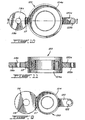
- seal J seal J comprises a tubular cylindrical cell 10 made of a rubbery material.
- Cell 10 is open at its upper and lower ends 12 and 14, respectively.
- Cell 10 can be made from a rectangular height panel equal to the height of the desired cell and width greater than the circumference of this cell. So, cell 10 is built in folding the panel back to make a tube while overlapping the longitudinal edges of the panel. The overlapping portions of the panel are affixed to one another with an adhesive.
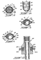
- a rigid cylindrical tip 16 is inserted so fixed in the upper end 12 of the cell 10 by means of retainers 18 provided on the periphery of the upper tip 16 and which penetrate partially in the cell 10 to grip it.
- the upper nozzle 16 is close to its edge free upper four holes 19 arranged so equidistant along the periphery of the tip 16. Two of the 19 holes are used for handling of the seal J, for example to using a crane; or a scaffolding equipped with a reel, for its insertion in the joint E expansion, while the other two holes 19 used to attach the seal J to the top of the dam B so that it hangs in the hole who receives it.
- a rigid lower end 20 having a cylindrical upper section and a section lower semi-spherical shape is inserted into the lower end 14 of the cell 10 and there is similarly fixed to the upper nozzle 16, that is, with retainers 22 practiced on the outer peripheral surface of the bottom nozzle 20 and which cling to the inner surface of the lower end 14 of cell 10.
- Retainers 24 are positioned and put in tension around the end lower 14 of the cell 10 opposite the section cylindrical of the lower nozzle 20 so as to produce a stronger connection between the cell 10 and the lower end 20.
- Two reinforcements 26 of elongated shape and section shaped circle segment are mounted from opposite and longitudinal way on both sides on the outside of the cell 10 (see Figure 2).
- These reinforcements 26 can be made of a hard material (such as "cord puller") so as to prevent a radial deflection of cell 10 at the level of installations of these reinforcements 26, even under the internal pressure exerted on the cell 10 when it is filled with liquid and put under voltage, as will be described in more detail when describing the installation of the joint J in the following text.
- the reinforcements 26 can, for example, be mounted to the cell 10 using glue. We also see the possibility of installing reinforcements 26 between layers of the cell 10.
- Retaining snares 28 are mounted at tension around cell 10 and reinforcements 26 vis-à-vis the upper end 16. These collars 28 have the same function as the snares of retainer 24 acting on the lower end 20.
- a retaining ring 30 is mounted so fixed to the inner surface of the upper nozzle 16 to the welding aid.
- This practical 30 ring retainer at its center a threaded opening that receives a plug 32 with threaded outer surface.
- Cap 32 includes a circular central opening 34 communicating with a tubing 33 on which is installed a valve 35 to allow the filling the seal J with liquid and perhaps of gas and to ensure the conservation of the pressure exerted by these in the joint J.
- At least two cables 36 are mounted at inside the cell 10 so as to connect the upper and lower ends 16 and 20, respectively.
- the cables 36 prevent the longitudinal deformation or lengthening of the cell 10 that could stem from his flexibility, its elasticity and the weight it supports.
- the upper ends of the cables 36 are mounted to the retaining ring 30 with the aid of 38 eyelet bolts welded to the retaining ring 30, while the lower ends of the cables 36 are retained at the conic section full of the lower end 20 also by bolts to eyelet 40 seals to this conical section by welding.
- the ends of the cables 36 engage in the holes of eyelet bolts 38 and 40 and are then folded back on themselves and maintained in position by clamps 42. It would be possible to eliminate cables 36 and, in this case, the stretching resistance of the cell 10 would be undertaken by the reinforcements 26.
- the upper and lower tips 16 and 20 are, in the illustrated construction, made of a stainless steel.
- the retaining ring 30 is welded to the upper end 16 and the eyelet bolts 38 are welded to the retaining ring 30.
- the bolts to eyelet 40 are welded to the lower end 20.
- end caps 16 and 20 of material plastic, such as nylon, and mounting using adhesive or other parts that must attach to it, i.e. the retaining ring 30 and the bolts eyelet 38 and 40. Screwing eyelet bolts 38 and 40 is also provided instead or in addition of the adhesive.
- the advantage of plastic over stainless steel lies in what can be drilled at through plastic end caps if the seal seal J gets stuck in the hole 70 for a reason or another.
- Guide rings 44 are mounted spaced way along each of the reinforcements 26 (see also Figure 3).
- a guide sleeve 46 which includes an arcuate base 48 (see Figure 4) disposed between the reinforcement 26 and cell 10 and that also includes a section tubular 50 threaded internal surface attached to the base 48 by a neck 52 in the shape of a small plate arranged longitudinally along the cell 10 and projecting radially from it.
- This neck 52 is preferably screwed to the arcuate base 48 to allow guide sleeves 46 and, more particularly, to their tubular sections 50 and their necks 52 to be removed from the joint J.
- a guide adapter 54 is screwed to its lower end 56 with the help of a net left in the threaded tube 50 of each of two guide sleeves 46.
- the upper end of each guide adapter 54 includes a tubular cylindrical section 58 providing a net in its central opening.
- a guide rod 60 of shape cylindrical is slid opposite each of the reinforcements 26 in the guide rings 44 respective for the installation of the seal J in the expansion joint E.
- the ends lower guide rods 60 provide each a threaded section that screws into the section tubular cylindrical 58 of a guide adapter 54 respective.
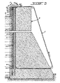
- FIGS 5 to 7 illustrate a method to produce an expansion joint E in a dam-weight B, this expansion joint E being consisting mainly of a vertical fault or cut created following several steps across the dam B and practically all the way up and by positioning the seal J in the cut in the B dam
- the first is to drill holes in the dam which are completely vertical to using a vertical drilling rig controlled by the Applicant and which makes part of public knowledge.
- the second type digging corresponds to a borehole whose verticality is ensured by a guiding device connected to two vertically drilled holes that are maybe the result of vertical drilling controlled.
- This guiding device represents a another aspect of the present invention which will be described in detail later in the text with reference to Figures 8 to 15.
- the third type of digging uses a diamond cable C which represents a modification of similar cables used in quarries for various sawing activities. A such diamond wire C creates a break in the dam B of constant width (10 to 15 millimeters width), while drilling done following the first two types of digging briefly described above produce circular holes that overlap in order to form in the dam B a continuous cut but whose width varies.
- a template 84 is used to ensure inter alia the orientation of the dam B cutoff for produce the expansion joint E. Indeed, the template 84 allows the alignment of the holes forming the cutting the expansion joint E following a pre-established orientation.
- the first four holes are drilled, that is to say the holes 62, 64, 66 and 68.
- These holes that are dug using the device controlled vertical drilling are practiced in the dam B to ride on both sides the two holes 70 and 74 provided to receive the seals J.
- the holes 62, 64, 66 and 68 being perfectly vertical, we now use a drilling device mounted to the device guidance for overlapping and parallel drilling between them to dig the circular holes 70, 72, 74 and 76.
- the seal J is down into hole 70 using a crane or another which clings to two of the holes 19 of the mouthpiece top 16 of the seal J.
- the semi-spherical shape of the bottom nozzle 20 attends to inserting and lowering the seal J in the hole 70 whose progression in the hole 70 is under the same weight of the seal J.
- the guide rods 60 are inserted into the holes 62 and 64 which overlap on both sides the hole 70 receiving the seal J to guide the seal in its hole 70.
- the reinforcements 26 are positioned vis-à-vis the cut and thus form an obstacle to the deformation of the cell 10 in direction and partially to inside the holes 62 and 64 that could flow the effect of radial pressure to the outside in the cell 10.
- each reinforcement 26 The vertical edges of the each reinforcement 26 are leaning against the wall internal hole 70 on both sides of the opening communicating with holes 62 and 64 due to overlapping holes.
- the seal J seal could be installed in the hole 70 using only one of the guide rods 60.
- joint J can be installed from so that the lower end 20 sits at the bottom of the hole 70, as shown in FIG. 5A.
- the lower nozzle 20 can be positioned way to be suspended in the hole 70 (see figure 5) to leave a game in hole 70.
- the seal J is then attached to the dam B by connecting the two other holes 19 of the upper nozzle 16 to the concrete of the upper end of the hole 70.
- the seal J is then filled with a non liquid frost (at least in regions subject to low temperatures); such as antifreeze that does not attack the seal rubber J ("Prestone TM").
- Pressurized gas can then be introduced into the cell 10 to obtain the desired pressure therein.
- the cap 32 is closed so as to seal the cell 10 to maintain it under pressure.
- the guide rods 60 are then unscrewed from the guide adapters 54 of the rod and slidably removed from the guide rings 44 and the hole 74. It is noted that the insertion of the seal J into the hole 70 under the effect Its own weight is facilitated if the cell 10 is gradually filled with its liquid.
- the walls of the hole 70 may be lubricated for example by means of bentonite or a polymer-based fluid.
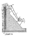
- a hole horizontal can be drilled to join the front from dam B to hole 68 and thus allow the cable diamond C to go around the dam B as it is see Figure 5.
- Other arrangements may be used for the diamond cable route, for example, in cases where the horizontal hole should join a narrow cut. In this case and in others, one can use a another method of using diamond wire C, as shown in Figure 5A.
- the diamond wire C is guided by a movable pulley that is mounted, by example, to a hydraulic cylinder 90 and by guide pulleys 92.
- the movable pulley 88 is inserted at a certain depth (10 feet, for example) in the holes adjacent to the cut you want using the diamond wire C.
- One of the two sections of the diamond wire that come out of these holes is guided by the pulley 92 located above dam B, while the other section of cable leans on top of the dam so there press down and cut the dam gradually down.
- the cutoff 82 is almost made at the pulley mobile 88, the diamond wire C has no longer any force on concrete and can not, therefore, continue to cut the dam B.
- Scaffolding mobile 94 can be used to ensure in any time a proper sawing effort on the dam B.
- the reinforcements 26 are dimensioned in length so that they extend towards the down to at least the lower extremities of holes 62 and 64 adjacent to the hole 70 in which locates the seal J.
- the second joint J can used to readjust the first seal J in his hole 70.
- cell 10 of the first seal J may have become slightly twisted in its hole 70.
- Figure 1A illustrates another lower end of the seal J. More particularly, a pulley 96 is mounted to rotation in the lower nozzle 20, and a cable 98 is engaged around the pulley 96 and then goes back vertically on both sides of cell 10. The pulley 96 and the cable 98 replace the rods of 60 guidance used when installing the seal J. The cable 98 passes through the guide rings 44 and spring over the dam B. The seal J went down into the hole 70 being suspended by the cable 98. A Once the installation is complete, the 98 cable can be removed by pulling on one of its ends, or he can be left in place in hole 70 for the possible future readjustment of the J joint or for its replacement. If the cable 98 is removed from the joint J, the subsequent withdrawal of the latter of its hole 70 shall be made using the guide rods 60.
- the guiding device according to the present invention for overlapping and parallel drilling can take many forms depending on the position of the hole that needs to be dug out to the two holes already drilled and whose verticality is established.
- the guiding device ensures the link using pads between a guide sliding in one or more existing holes and a trepan. This allows a parallel hole to be drilled one or those existing. By repeating the same operations, a break can be achieved.
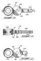
- the guides have appropriate shapes and dimensions to slide in the existing hole or holes. Through For example, in Figure 8, we drill the hole 72 located between holes 64 and 66 already drilled at using vertical drilling rig controlled and which will serve as a guide.
- the guiding device will be type "G-F-G", where "G” indicates a guide and “F” indicates A drilling; therefore, “G-F-G” indicates drilling a hole between two existing and vertical holes that serve as a guide to ensure verticality of the new hole and to ensure that the three holes have longitudinal axes located in the same vertical plane.
- the guiding device required to drill hole 72 using as a guide the holes 64 and 66 will be the type "G4-F4-G4", where the figures indicate the diameters of the guide holes and the hole to be drilled.
- the two devices of "G4-F4-G4" which are each identified by the reference number 100 are arranged remotely vertical one above the other and are connected by adjustment rods 102 which are screwed to guiding devices 100 so as to allow their adjustment so that the two guiding devices 100 are parallel to each other.
- a device drilling usually indicated by F went up to rotation to the guiding devices 100 using pads 104 to ensure the devices of 100 guiding a movement purely in translation down along the guide holes 64 and 66 then that the drill rig F moves down while turning on himself to dig the hole 72.
- the drilling device F comprises the parts following conventional methods: a train of rods 106, a reamer sleeve 108, a corer 110 and a coring ring 112.
- One of the rods 102 is provided with flexible guides 114 to prevent jamming of the drilling device F.
- Each flexible guide 114 is in the form of a disk horizontal diameter slightly smaller than hole diameter 66 of FIG.
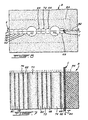
- Figure 9 illustrates the device of guide 100 which includes the bushing assembly forced 104, a guide disc 116 of diameter nearly identical to the guide hole 64 and provided with a opening 118 for receiving the adjustment rod 102, and an extension 120 for the guide hole 66 and also provided with an opening 122 for receive the other adjustment rod 102.
- One piece any connection 117 joins the pad forced assembly 104 to the guide disc 116.
- This connecting piece 117 has a slightly width less than the overlap of holes 64 and 72. Similar way, the width of the extension 120 corresponds to the overlap of holes 72 and 66.
- the guide disc 116 and the extension 120 ensures the vertical descent of the drilling device F, preventing the latter from following a movement helical that drilling activity would encourage.
- the guide disc 116 ensures the verticality of the new hole drilled by the drilling device F while the extension 120 ensures that the three holes are aligned longitudinal coplanar.
- the extension 120 and the flexible guide 114 allow a game between the holes that are obviously not perfectly parallel; in addition, they prevent the movement of spiral of the drilling device F.
- the rubber of the flexible guide 114 prevents jamming of the device drilling F since it behaves similar to that of a chimney brush as it follows the walls of the hole while deflecting on its periphery against the direction of movement of the drilling device F.
- extension 120 by a second guide disc identical to the guide disc 116 (and, consequently, in diameter similar to Guide Hole 66) would provide the guiding device 100 a too rigid structure, which would cause the breakage of the latter and / or perhaps that of the drilling rig F.
- widths of the connecting piece 117 and the extension 120 ensure alignment of holes 64, 66 and 72 since they offer little play compared to the width of their respective overlap. Also, replacing the guide disc 116 with an extension similar to the extension 120 would make sure that the drilling device F would exert too much pressure on the edges defined by the overlaps of the holes concerned.
- Figures 10 and 11 illustrate a guidance device 123 of the type "G4-F8-G4" which is used to drill a hole 8 inches in diameter between two pilot holes 4 inches in diameter each.
- This type of device is used to drill holes 70 and 74 (which receive the joints J) between the holes 62 and 64, and 66 and 68, respectively.
- an adapter 124 as shown in Figure 12 is used to rotate the guide device "G4-F8-G4" to the drilling device F.
- the adapter 124 includes among others a pad 126 and a ring restraint 128.
- Figures 13 and 14 illustrate a guidance device 130 of the type "F4-G4-G8" which is when the two pilot holes are overlap, to drill a third vertical hole overlapping one of the two guide holes.
- the guiding device 130 is used to drill the hole 76 of Figures 5 and 6 which has 4 inches of diameter, the guide holes being holes 62 and 70 having respectively 4 and 8 inches in diameter.
- Figure 15 illustrates a device for guidance 132 of the type "F4-G4-G4" which is also used when both guide holes overlap to drill a third vertical hole overlapping one of the two guide holes.
- the guiding device 132 is used to drill holes 78 and 80 of Figures 5 and 6 each having 4 inches in diameter.
- the guide holes for the hole to be drilled 78 are the holes 76 and 62, while for the hole 80, the guide holes are holes 78 and 76, all those holes each having 4 inches in diameter.
- the seal will absorb or compensate for the relative movements of various sections of the dam. Indeed, for correct anomalies in the behavior of dams, it is sometimes necessary to practice cuts.
- This device ensures the sealing cuts and following the subsequent deformations of the dams.
- the device is composed of two cells made of elastic materials reinforced, inserted in pre-drilled holes in the plan of the cut. For the tensioning of cells, these are filled with a liquid (no gel if required) and additional pressure gas is maintained.
- the guidance device for drilling overlap and parallels between them was developed for cell installation sealing, during cuts of dams. However, the same device can be used to all other cuts by drilling.
- the seal J following the present invention can also be used in other applications involving works in concrete and perhaps in works made of other rigid materials, such as stone, metal structures, etc.
- the J joint could be implanted in oil recovery ponds undergoing stress due, for example, to the ground in order to solve the environmental problems that can be caused by an oil leak in the ground.
- the cell could be built of a synthetic material, or rubber cell could be coated with a protective coating.
- the seal J could also be used for repair work, temporary or permanent.
- cement grout or other that has been injected leaks frequently by the cut itself downstream side and on the upstream side before it can solidify. Therefore, one installs easily downstream of the cut a temporary clogging structure for prevent the grout from escaping.
- a recovery basin for example, could be boxed so as to define cuts on two of its walls. During the formwork, a hole would be provided on each of the cuts. A cardboard tube could be installed in each hole and be subsequently removed before installing the seal sealing. The installation of seals in the holes of each of the expansion joints would seal the pelvis and allow it to move to over the years without breaking.
Landscapes
- Engineering & Computer Science (AREA)
- Geology (AREA)
- Life Sciences & Earth Sciences (AREA)
- Mining & Mineral Resources (AREA)
- Environmental & Geological Engineering (AREA)
- Geochemistry & Mineralogy (AREA)
- Fluid Mechanics (AREA)
- General Life Sciences & Earth Sciences (AREA)
- Physics & Mathematics (AREA)
- General Engineering & Computer Science (AREA)
- Mechanical Engineering (AREA)
- Structural Engineering (AREA)
- Ocean & Marine Engineering (AREA)
- Civil Engineering (AREA)
- Working Measures On Existing Buildindgs (AREA)
- Underground Structures, Protecting, Testing And Restoring Foundations (AREA)
- Building Environments (AREA)
Abstract
Description
La présente invention traite d'ouvrages en béton, tels que des barrages-poids et, plus particulièrement, d'un dispositif d'étanchéité pour scellement de joints d'expansion coupés dans des barrages de ce type.The present invention deals with concrete, such as gravity dams and, more particularly, a sealing device for sealing expansion joints cut in dams of this type.
Le brevet américain no 4,655,638 divulgue une méthode d'imperméabilisation d'une ouverture dans un barrage en béton. Selon cette méthode, un trou est foré sur l'ouverture pour recevoir un membre tubulaire et élastique comprenant une couche interne imperméable et une couche externe enduit d'une résine possédant des propriétés adhésives afin de procurer une bonne adhérence du membre tubulaire aux parois du trou. Le membre tubulaire possède une extrémité supérieure ouverte et une extrémité inférieure fermée. Une fois l'étape d'installation complétée, le membre tubulaire est rempli à l'aide d'un fluide non gazeux et élastique. Un appareil d'inversion opérationnel pour diriger un fluide pressurisé à l'intérieur du membre tubulaire est utilisé pour installer ce dernier dans le trou.U.S. Patent No. 4,655,638 discloses a method waterproofing of an opening in a concrete dam. According to this method, a hole is drilled on the opening to receive a member tubular and elastic comprising an impervious inner layer and a outer layer coated with a resin having adhesive properties to provide good adhesion of the tubular member to the walls of the hole. The tubular member has an open upper end and an end lower closed. Once the installation step is completed, the tubular member is filled with a non-gaseous and elastic fluid. An inversion device operable to direct a pressurized fluid inside the tubular member is used to install the latter in the hole.
Le brevet américain no 3,342 033 divulgue un dispositif d'étanchéité comprenant un sac flexible utilisé pour former un joint d'étanchéité à la jonction d'un poteau et d'un mur. Le sac est installé dans l'espace défini par un encastrement longitudinal ménagé dans le poteau et une rainure se prolongeant le long d'une extrémité du mur. Une fois en position, le sac est rempli d'un matériau durcissant , tel qu'un ciment.No. 3,342,033 discloses a sealing device comprising a flexible bag used to form a seal at the junction of a pole and a wall. The bag is installed in the space defined by a longitudinal embedding formed in the post and a groove extending the along one end of the wall. Once in position, the bag is filled with a hardening material, such as cement.
Les barrages en béton, soit les barrages-poids, les barrages à arcs (en voûte), ou même les barrages à joints peuvent souffrir de problèmes de comportement tels que, pour les barrages sans joints, la fissuration du barrage due au travail, ou le gonflement du barrage dû, par exemple, aux réactions chimiques dans le barrage. Dans le cas des barrages à joints, il arrive que les joints coulent.Concrete dams, ie dams, arch dams (vaulted), or even joint dams may suffer from behavior such as, for dams without joints, cracking of the dam due to work, or the swelling of the dam due, for example, to chemical reactions in the dam. In the case of Joint dams, seals may leak.
Pour réparer les barrages en béton ainsi affectés, on doit créer un joint pour empêcher la transmission des efforts, diminuer les contraintes internes et laisser de l'espace pour le gain de volume ultérieur du béton. Les méthodes actuellement connues sont compliquées et très coûteuses. La section à couper nécessite d'abord la construction d'un batardeau (caisson) du côté mouillé ou en amont du barrage qui a la hauteur du barrage pour éviter le passage ce l'eau dans la coupure durant les travaux. Un tel batardeau est sujet à des pressions très élevées d'où il présente des problèmes de sécurité qui sont partiellement résolus par une installation très coûteuse. Les travaux doivent être effectués par des plongeurs et même par des To repair concrete dams as well affected, a seal must be created to prevent the transmission of efforts, reduce constraints and leave space for the gain of subsequent volume of the concrete. The methods currently known are complicated and very expensive. The cutting section requires first the construction a cofferdam (caisson) on the wet side or upstream of the dam at the height of the dam to avoid the passage this water in the cut during the works. Such a cofferdam is subject to pressure very high where it presents problems of security which are partially solved by a very expensive installation. The work must be carried out by divers and even by
scaphandriers selon les profondeurs. De plus, il est nécessaire de continuellement pomper l'eau qui s'infiltre dans le coffre formé entre le batardeau et le barrage. Les réparations de barrages en béton selon cette méthode sont donc très dispendieuses. Une fois les travaux terminés, il est très avantageux de remplacer le système de batardeau par un dispositif d'étanchéité. A ce jour, il n'existe aucun dispositif connu de ce genre efficace à long terme. divers according to the depths. In addition, it is necessary to continually pump the water that infiltrates the trunk formed between the cofferdam and the dam. Repairs of concrete dams according to this method are therefore very expensive. Once the work is finished, it is very advantageous to replace the cofferdam system with a sealing device. To date, there is no no known device of this kind effective long term.
Pour offrir des joints d'expansion aux barrages en béton, certains essais ont été effectués avec l'insertion entre les sections en béton du barrage de joints en matériaux plastiques. Cependant, une fois écrasé par le déplacement du barrage, le joint en plastique ne reprend pas sa forme initiale lorsque le barrage revient à sa position originale, ce qui résulte en des joints qui coulent. De plus, il n'y a pas d'adhérence entre le joint en plastique et le béton du barrage. L'utilisation de joints en calfeutrage produirait les mêmes résultats puisqu'ils sécheraient au bout d'une ou deux années.To offer expansion joints to concrete dams, some tests have been carried out with the insertion between the concrete sections of the dam of joints in plastic materials. However, once crushed by the displacement of the dam, the plastic seal does not resume its initial form when the dam returns to its original position, resulting in joints that flow. Moreover, there is no adhesion between the plastic seal and concrete dam. The use of caulk joints would produce the same results since they would dry out after one or two years.
Pour produire des joints d'expansion dans des barrages en béton, il a également été proposé de construire les barrages en plusieurs sections distinctes et emboítées et séparées par un espace vide qui sert de jeu lors des déplacements.. des diverses sections du barrage. Chaque section du barrage est coffrée de façon indépendante avec emboítement espacé pour produire le joint. Pour sceller l'extrémité du joint située du côté de l'eau, on installe des lamelles d'étanchéité qui s'ajustent lorsque les sections du barrage se déplacent les unes par rapport aux autres de sorte à ce que le barrage conserve son caractère étanche. Comme les espaces entre les diverses sections du barrage qui servent de joints se remplissent avec le temps de calcaire et autres, le vide se bloque, éliminant ainsi le jeu entre les sections de barrage et, par conséquent, le joint d'expansion lui-même.To produce expansion joints in concrete dams, it has also been proposed to build dams into several sections separate and nested and separated by a space empty that serves as a game when moving .. various sections of the dam. Each section of dam is cased independently with nested spacing to produce the seal. For seal the end of the seal located on the side of water, we install sealing slats which adjust when the sections of the dam are move relative to each other so as to that the dam retains its waterproof character. As the spaces between the various sections of the dam that serve as seals fill up with the time of limestone and others, the vacuum is blocked, eliminating the play between the dam sections and, therefore, the expansion joint itself.
La présente invention a donc pour but de mettre au point un dispositif d'étanchéité pour des ouvrages en béton.The present invention therefore aims to develop a sealing device for concrete structures.
La présente invention a également pour but de mettre au point un dispositif d'étanchéité pour scellement de joints d'expansion coupés dans les barrages en béton qui s'adapte aux mouvements du barrage.The present invention also aims to develop a sealing device for sealing of expansion joints cut in concrete dams that adapts to the movements of the barrage.
La présente invention a également pour but de mettre au point un dispositif d'étanchéité pour ouvrages en béton qui est de fabrication économique et d'installation facile, sécuritaire et relativement peu coûteuse en remplacement des dispositifs d'étanchéité peu efficaces utilisés à ce jour. L'étanchement des coupures pratiquées dans les barrages pour corriger des anomalies de comportement veut être accompli par une méthode simple et relativement peu coûteuse à l'aide d'un joint d'étanchéité efficace et également relativement peu coûteux.The present invention also aims to develop a sealing device for concrete structures that are of economical manufacture and easy installation, safe and relatively inexpensive to replace less effective sealing devices used for this purpose day. The sealing of cuts made in dams to correct behavioral abnormalities wants to be accomplished by a simple method and relatively inexpensive using a seal effective sealing and also relatively little expensive.
La présente invention a également pour but de mettre au point une méthode pour créer dans un barrage en béton un joint d'expansion caractérisé par un dispositif d'étanchéité suivant la présente invention. Une méthode est aussi proposée pour remplacer un dispositif d'étanchéité suivant la présente invention par un nouveau joint d'étanchéité. Une méthode est également proposée pour éviter l'installation d'un batardeau en amont du barrage.The present invention also aims to develop a method to create in a concrete dam an expansion joint characterized by a sealing device according to the present invention. A method is also proposed for replace a sealing device according to the present invention by a new seal sealing. A method is also proposed to prevent the installation of a cofferdam upstream of the dam.
La présente invention a également pour but de mettre au point un dispositif de guidage pour des forages avec chevauchement et parallèles entre eux en vue de permettre, entre autres, l'installation dans un barrage en béton d'un joint d'expansion caractérisé par un dispositif d'étanchéité suivant la présente invention. The present invention also aims to develop a guidance device for overlapping and parallel drilling to allow, inter alia, the installation of in a concrete dam an expansion joint characterized by a following sealing device the present invention.
Telle que revendiquée, l'invention propose un dispositif d'étanchéité pour scellement d'une ouverture pratiquée dans un ouvrage en béton comprenant une cellule faite d'un matériau élastique et incluant au moins une section tubulaire, la cellule étant pourvue à ses extrémités supérieure et inférieure respectivement d'un embout supérieur rigide et d'un embout inférieur rigide, la surface inférieure de l'embout inférieur étant formée pour faciliter l'insertion du dispositif d'étanchéité dans un trou pratiqué sur l'ouverture, des moyens peu extensibles montés entre les embouts supérieur et inférieur pour empêcher l'étirement longitudinal de la cellule , la cellule incluant des moyens de renfort espacés l'un par rapport à l'autre et disposés vis-à-vis l'ouverture pour empêcher la déformation de la cellule dans l'ouverture, un espace périphérique continu étant défini sur la cellule entre les extrémités inférieures des moyens de renfort et l'extrémité supérieure de l'embout inférieur , et des moyens pour permettre le positionne-ment et l'installation du dispositif d'étanchéité .As claimed, the invention proposes a sealing device for sealing of an opening made in a concrete structure comprising a cell made of an elastic material and including at least one tubular section, the cell being provided at its upper ends and bottom respectively of a mouthpiece upper rigid and lower end rigid, the bottom surface of the mouthpiece lower being formed to facilitate the insertion of the sealing device in hole on the opening, means that are not extensible upper and lower tips for prevent longitudinal stretching of the cell , the cell including means of reinforcement spaced apart from each other and arranged opposite the opening to prevent the deformation of the cell in the opening, a continuous peripheral space being defined on the cell between lower ends of the reinforcement means and the upper end of the mouthpiece lower, and means to allow positioning and the installation of the sealing device.
Selon un mode de réalisation les embouts supérieur et inférieur comportent chacun au moins une section cylindrique, la cellule formant un cylindre recouvrant de façon fixe à ses extrémités supérieure et inférieure les sections cylindriques respectives des embouts supérieur et inférieurAccording to one embodiment, the end pieces upper and lower each at least one cylindrical section, the cell forming a cylinder covering fixed way at its upper ends and lower the cylindrical sections respective upper and lower ends
Les sections cylindriques des embouts supérieur et inférieur ménagent chacun des arrêts de retenue sur leur périphérie respective qui engagent respectivement les extrémités supérieure et inférieure de la cellule cylindrique pour assurer leur assemblage, des collets de retenue étant montés autour des extrémités supérieure et inférieure de la cellule pour renforcer ledit assemblage.The sections cylindrical upper and lower ends provide each of the restraining stops on their respective periphery which respectively engage the ends upper and lower cell cylindrical to ensure their assembly, retaining collars being mounted around the upper and lower extremities of the cell to reinforce the said assembly.
L'embout inférieur comprend une section semi-sphérique à l'extrémité inférieure de sa section cylindrique.The bottom nozzle includes a semi-spherical section to the lower end of its section cylindrical.
Les moyens peu extensibles comprennent au moins un câble monté tendu dans la cellule , les extrémités de chaque câble étant fixées à leur embout respectif à l'aide de moyens d'attacheThe means extensible include at least one cable mounted tightly in the cell, the ends of each cable being attached to their respective mouthpiece using means attachment
Lesdits moyens d'attache comprennent des boulons à oeillet .Said means fasteners include bolts to eyelet.
Selon un mode de réalisation l'embout supérieur comprend un anneau de retenue monté à l'intérieur de sa section cylindrique, l'anneau de retenue pratiquant une ouverture centrale filetée recevant un bouchon , le bouchon incluant une ouverture reliée à une tubulure qui comprend une soupape pour permettre l'entrée d'au moins un fluide dans la cellule et assurer le maintien de la pression désirée de fluide dans la cellule .According to one embodiment the upper endpiece includes a retaining ring mounted to inside its cylindrical section, the ring restraint practicing an opening central threaded receiving a plug, the cap including a connected opening to a manifold that includes a valve to allow the entry of at least one fluid in the cell and ensure the maintaining the desired fluid pressure in the cell .
La cellule est faite d'un matériau caoutchouteux.The cell is made of a rubbery material.
L'embout supérieur comprend des moyens pour la manipulation du dispositif d'étanchéité et pour sa fixation à l'ouvrage.The upper end includes means for the manipulation of the sealing device and for its attachment to the work.
Les moyens de renfort comprennent deux renforts longitudinaux disposés extérieurement de part et d'autre de la cellule .The means of reinforcement include two reinforcements longitudinals arranged externally on both sides of the cell.
Les renforts sont faits d'un matériau rigide et sont collés sur la cellule .The reinforcements are made of a rigid material and are glued on the cell.
Selon un mode de réalisation lesdits moyens pour permettre le positionnement et l'installation du dispositif d'étanchéité comprennent des anneaux de guidage disposés extérieurement le long de chacun des renforts et s'engageant dans l'ouverture, une poulie montée verticalement au bas de l'embout inférieur, et un câble engageant la poulie et remontant de part et d'autre de la cellule tout en passant au travers des anneaux de guidage respectifs des deux renforts.According to one embodiment, said means to allow positioning and the installation of the sealing device include guide rings arranged externally along each of the reinforcements and engaging in the opening, a pulley mounted vertically at the bottom of the bottom nozzle, and a cable engaging the pulley and going up from and other cell while passing through guide rings respective reinforcements.
Lesdits anneaux de guidage ont chacun une base arquée disposée entre la cellule et un renfort respectifSaid rings of guidance each have an arched base arranged between the cell and a backup respective
Selon um mode de réalisation le dispositif d'installation comprend des anneaux de guidage disposés le long de chacun des renforts et s'engageant dans l'ouverture, au moins une tige de guidage passant au travers des anneaux de guidage respectifs d'un des deux renforts et incluant une extrémité inférieure filetée, un manchon de guidage monté au bas du renfort et ménageant une ouverture centrale filetée pour recevoir une tige de guidage respective.According to one embodiment the device installation includes guide rings arranged along each of the reinforcements and engaging in the opening, at least one guide rod passing through guide rings respective of one of the two reinforcements and including a threaded lower end, a guide sleeve mounted at the bottom of the reinforcement and providing a central opening threaded to receive a guide rod respectively.
Lesdits anneaux de guidage ont chacun une base arquée disposée entre la cellule et un renfort respectif , une tige de guidage étant prévue pour les anneaux de guidage de chacun des deux renfortsSaid rings of guidance each have an arched base arranged between the cell and a backup respective, a guide rod being provided for the guide rings of each of the two reinforcements
L'invention propose également
une méthode d'installation d'un joint
d'expansion dans un ouvrage en béton à
l'aide d'un dispositif d'étanchéité qui
comprend une cellule tubulaire et élastique
pourvue à ses extrémités supérieure et
inférieure respectivement d'un embout
supérieur rigide et d'un embout inférieur
rigide la surface inférieure de l'embout
inférieur étant formée pour faciliter
l'insertion du dispositif d'étanchéité dans
l'ouvrage en béton, des moyens peu
extensibles montés entre les embouts
supérieur et inférieur , la cellule
incluant des moyens de renfort espacés
l'un par rapport à l'autre, un espace
périphérique continu étant défini sur la
cellule entre les extrémités inférieures
des moyens de renfort et l'extrémité
supérieure de l'embout inférieur , la
méthode incluant les étapes suivantes:
Selon une mode de mise en oeuvre avant l'etape b), un deuxième et un troisième trous sont forés avec chevauchement de part et d'autre du premier trou pour faciliter les étapes b) et d).According to a mode of implementation before step b), a second and a third holes are drilled with overlap on both sides of the first hole to facilitate steps b) and d).
Avant l'étape d), un quatrième trou (74) est foré, ce quatrième trou étant destiné à recevoir un deuxième dispositif d'étanchéité similaire à celui du premier trou , et dans laquelle, dans l'étape d), la coupure d'achèvement du joint d'expansion rejoint également le quatrième trou.Before step d), a fourth hole (74) is drilled, this fourth hole being intended to receive a second device similar to that of the first hole, and in which, in step d), the completion cutoff of the expansion joint also joins the fourth hole.
Un deuxième dispositif d'étanchéité est installé dans le quatrième trou et est ensuite rempli d'un fluide approprié.A second sealing device is installed in the fourth hole and is then filled with a suitable fluid.
Le deuxième dispositif d'étanchéité est rempli sous pression requise à l'aide d'au moins un fluide approprié.The second sealing device is filled under pressure required using at least one suitable fluid.
Selon un mode de mise en oeuvre le dispositif d'étanchéité comprend un dispositif d'installation incluant des anneaux de guidage disposés extérieurement le long de chacun des moyens de renfort , une poulie étant montée verticalement au bas de l'embout inférieur , et un câble étant engagé sur la poulie et remontant de part et d'autre de la cellule tout en passant au travers des anneaux de guidage respectifs des moyens de renfort , la méthode comprenant, dans l'étape b), l'introduction des anneaux de guidage dans les deuxième et troisième trous .According to one embodiment, the sealing device includes an installation device including guide rings arranged externally along each of the reinforcement means, a pulley being vertically mounted at the bottom of the mouthpiece lower, and a cable being engaged on the pulley and going up from hand and else from the cell while moving on to through respective guide rings reinforcement means, the method including, in step (b), the introduction of guide rings in the second and third hole.
Selon un mode de mise en oeuvre le dispositif d'étanchéité comprend un dispositif d'installation incluant des anneaux de guidage disposés extérieurement le long de chacun des moyens de renfort, au moins une tige de guidage passant au travers des anneaux de guidage respectifs d'un des moyens de renfort et incluant une extrémité inférieure filetée, un manchon de guidage monté au bas du moyen de renfort et ménageant une ouverture centrale filetée recevant une tige de guidage respective, la méthode comprenant, dans l'étape b), l'introduction de la tige de guidage et de ses anneaux de guidage dans l'un des deuxième et troisième trous , la fixation du dispositif d'étanchéité à l'ouvrage, puis le dévissage de la tige de guidage du manchon de guidage , et enfin le retrait de la tige de guidage de son trou .According to one embodiment, the sealing device includes an installation device including guide rings arranged externally along each reinforcement means, at least one rod guide passing through the rings respective guidance of one of the means of reinforcement and including one end lower threaded, a guide sleeve mounted at the bottom of the reinforcing means and providing a central threaded opening receiving a respective guide rod, the method comprising, in step b), the introduction of the guide rod and its guide rings in one of second and third holes the fixing the sealing device to the work, then unscrewing the stem of guiding the guide sleeve, and finally the withdrawal of the guide rod from his hole.
Une tige de guidage (60) est utilisee pour chacun des deuxième et troisième trous , chaque tige de guidage étant associée à un des moyens de renfort . A guide rod (60) is used for each of the second and third holes each guide pin being associated with one of the reinforcement means.
L'invention propose également une méthode pour le réajustement d'un
dispositif d'étanchéité d'un joint
d'expansion coupé dans un barrage en béton
, le dispositif d'étanchéité comprenant
une cellule tubulaire et élastique pourvue
à ses extrémités supérieure et
inférieure respectivement d'un embout supérieur
rigide et d'un embout inférieur rigide
, la surface inférieure de l'embout
inférieur étant formée pour faciliter
l'insertion du dispositif d'étanchéité dans
le barrage, des moyens peu extensibles
montés entre les embouts supérieur et inférieur,
la cellule incluant des moyens de
renfort espacés l'un par rapport à
l'autre, un espace périphérique continu étant
défini sur la cellule entre les extrémités
inférieures des moyens de renfort et
l'extrémité supérieure de l'embout inférieur
, le dispositif d'étanchéité étant
installé dans un premier trou ménagé dans
le barrage en béton sur le joint
d'expansion , ses moyens de renfort
étant positionnés dans le sens d'écoulement de
l'eau, la cellule étant en tension à
l'aide d'au moins un fluide approprié, un
deuxième dispositif d'étanchéité , similaire
au dispositif d'étanchéité du premier trou
, étant installé dans un deuxième trou
également pratiqué sur le joint d'expansion
, la méthode incluant les étapes suivantes:
L'installation et la mise en tension du deuxième dispositif d'étanchéité comprennent le forage d'un deuxième trou sur le joint d'expansion destiné à recevoir le deuxième dispositif d'étanchéité et le remplissage du deuxième dispositif d'étanchéité sous pression requise à l'aide du fluide approprié.Installation and tensioning the second sealing device include drilling a second hole on the expansion joint intended to receive the second sealing device and the filling of the second sealing device under pressure required using the fluid appropriate.
L'étape d) consiste à dépressuriser le deuxième dispositif d'étanchéité .Step d) is to depressurize the second device sealing.
L'invention propose également une méthode de remplacement d'un
dispositif d'étanchéité d'un joint
d'expansion coupé dans un barrage en béton
, le dispositif d'étanchéité comprenant
une cellule tubulaire et élastique pourvue
à ses extrémités supérieure et
inférieure respectivement d'un embout supérieur
rigide et d'un embout inférieur rigide
, la surface inférieure de l'embout
inférieur étant formée pour faciliter
l'insertion du dispositif d'étanchéité dans
le barrage, des moyens peu extensibles
montés entre les embouts supérieur et inférieur
, la cellule incluant des moyens de
renfort espacés l'un par rapport à
l'autre, un espace périphérique continu étant
défini sur la cellule entre les extrémités
inférieures des moyens de renfort et
l'extrémité supérieure de l'embout inférieur
, le dispositif d'étanchéité étant
installé dans un premier trou ménagé dans
le barrage en béton sur le joint
d'expansion , ses moyens de renfort
étant positionnés dans le sens d'écoulement de
l'eau, la cellule étant en tension à
l'aide d'au moins un fluide approprié, un
deuxième dispositif d'étanchéité , similaire
au dispositif d'étanchéité du premier trou
, étant installé dans un deuxième trou
également pratiqué sur le joint d'expansion
, la méthode incluant les étapes suivantes:
L'installation et la mise en tension du deuxième dispositif d'étanchéité comprennent le forage d'un deuxième trou sur le joint d'expansion destiné à recevoir le deuxième dispositif d'étanchéité et le remplissage du deuxième dispositif d'étanchéité sous pression requise à l'aide du fluide approprié.Installation and tensioning the second sealing device include drilling a second hole on the expansion joint intended to receive the second sealing device and the filling of the second sealing device under pressure required using the fluid appropriate.
L'étape e)
consiste à dépressuriser le deuxième dispositif
d'étanchéité .
Suivant la présente invention, les figures 1 à 5 illustrent un joint d'étanchéité J pour joints d'expansion E pratiqués dans un ouvrage en béton tel qu'un barrage-poids B. La coupure du joint d'expansion E dans le barrage B et l'installation du joint d'étanchéité J dans le joint d'expansion E seront décrits plus bas en détails avec référence aux figures 5 à 7.According to the present invention, the figures 1 to 5 illustrate a seal J for joints of expansion E practiced in a concrete structure such as a weight dam B. The cutting of the joint E expansion in the B dam and the installation of the seal J in the expansion joint E will be described below in detail with reference Figures 5 to 7.
Nous décrivons maintenant la structure du
joint d'étanchéité J. Le joint d'étanchéité J
comprend une cellule cylindrique tubulaire 10 faite
d'un matériau caoutchouteux. La cellule 10 est
ouverte à ses extrémités supérieure et inférieure 12
et 14, respectivement. La cellule 10 peut être faite
à partir d'un panneau rectangulaire de hauteur
égale à la hauteur de la cellule désirée et de
largeur supérieure à la circonférence de cette
cellule. Ainsi, la cellule 10 est construite en
repliant le panneau pour en faire un tube tout en
chevauchant les rebords longitudinaux du panneau.
Les portions du panneau qui se chevauchent sont
fixées l'une à l'autre à l'aide d'un adhésif. Un
embout cylindrique rigide 16 est inséré de façon
fixe dans l'extrémité supérieure 12 de la cellule 10
à l'aide d'arrêts de retenue 18 ménagés sur la
périphérie de l'embout supérieur 16 et qui pénètrent
partiellement dans la cellule 10 pour s'y agripper.
L'embout supérieur 16 ménage près de son rebord
libre supérieur quatre trous 19 disposés de façon
équidistante le long de la périphérie de l'embout
supérieur 16. Deux des trous 19 servent à la
manipulation du joint d'étanchéité J, par exemple à
l'aide d'une grue; ou d'un échafaudage muni d'un
dévidoir, pour son insertion dans le joint
d'expansion E, tandis que les deux autres trous 19
servent à fixer le joint d'étanchéité J au haut du
barrage B de sorte qu'il soit suspendu dans le trou
qui le reçoit.We now describe the structure of the
seal J seal J
comprises a tubular
Un embout inférieur rigide 20 ayant une
section supérieure cylindrique et une section
inférieure de forme semi-sphérique est inséré dans
l'extrémité inférieure 14 de la cellule 10 et y est
fixé de façon similaire à l'embout supérieur 16,
c'est-à-dire à l'aide d'arrêts de retenue 22
pratiqués sur la surface périphérique extérieure de
l'embout inférieur 20 et qui s'agrippent à la
surface intérieure de l'extrémité inférieure 14 de
la cellule 10. Des collets de retenue 24 sont
positionnés et mis en tension autour de l'extrémité
inférieure 14 de la cellule 10 vis-à-vis la section
cylindrique de l'embout inférieur 20 de façon à
produire une connexion plus solide entre la cellule
10 et l'embout inférieur 20.A rigid
Deux renforts 26 de forme allongée et de
section en forme de segment de cercle sont montés de
façon opposée et longitudinale de part et d'autre
sur l'extérieur de la cellule 10 (voir figure 2).
Ces renforts 26 peuvent être faits d'un matériau dur
(tel que du "tire-cord") de sorte à empêcher une
déflexion radiale de la cellule 10 au niveau des
installations de ces renforts 26, même sous l'effet
de la pression interne qui s'exerce sur la cellule
10 lorsqu'elle est remplie de liquide et mise sous
tension, tel qu'il le sera décrit plus en détails
lors de la description de l'installation du joint
d'étanchéité J dans le texte qui suit. Les renforts
26 peuvent, par exemple, être montés à la cellule 10
à l'aide de colle. On entrevoit également la
possibilité d'installer les renforts 26 entre les
couches de la cellule 10.Two
Des collets de retenue 28 sont montés à
tension autour de la cellule 10 et des renforts 26
vis-à-vis l'embout supérieur 16. Ces collets de
retenue 28 ont la même fonction que les collets de
retenue 24 qui agissent sur l'embout inférieur 20.Retaining snares 28 are mounted at
tension around
Un anneau de retenue 30 est monté de façon
fixe à la surface interne de l'embout supérieur 16 à
l'aide de soudure. Cet anneau de retenue 30 pratique
en son centre une ouverture filetée qui reçoit un
bouchon 32 à surface extérieure filetée. Le bouchon
32 comprend une ouverture centrale circulaire 34
communiquant avec une tubulure 33 sur laquelle est
installée une soupape 35 pour permettre le
remplissage du joint d'étanchéité J de liquide et
peut-être de gaz et pour assurer la conservation de
la pression exercée par ces derniers dans le joint
J.A retaining
Au moins deux câbles 36 sont montés à
l'intérieur de la cellule 10 de façon à connecter
les embouts supérieur et inférieur 16 et 20,
respectivement. Les câbles 36 empêchent la
déformation longitudinale ou l'allongement de la
cellule 10 qui pourraient découler de sa
flexibilité, de son élasticité et du poids qu'elle
supporte. Les extrémités supérieures des câbles 36
sont montées à l'anneau de retenue 30 à l'aide de
boulons à oeillet 38 soudés à l'anneau de retenue
30, alors que les extrémités inférieures des câbles
36 sont retenues à la section conique pleine de
l'embout inférieure 20 également par des boulons à
oeillet 40 joints à cette section conique par
soudure. Les extrémités des câbles 36 s'engagent
dans les trous des boulons à oeillet 38 et 40 et
sont ensuite repliées sur elles-mêmes et maintenues
en position par des collets de serrage 42. Il
serait possible d'éliminer les câbles 36 et, dans ce
cas, la résistance à l'étirement de la cellule 10
serait entreprise par les renforts 26.At least two
Les embouts supérieur et inférieur 16 et
20 sont, dans la construction illustrée, fait d'un
acier inoxydable. L'anneau de retenue 30 est soudé à
l'embout supérieur 16 et les boulons à oeillet 38
sont soudés à l'anneau de retenue 30. Les boulons à
oeillet 40 sont soudés à l'embout inférieur 20. On
prévoit également des embouts 16 et 20 en matériau
plastique, tel que le nylon, et un montage à l'aide
d'adhésif ou autre des pièces qui doivent s'y fixer,
c'est-à-dire l'anneau de retenue 30 et les boulons à
oeillet 38 et 40. Le vissage des boulons à oeillet
38 et 40 est également prévu à la place ou en plus
de l'adhésif. L'avantage du plastique par rapport à
l'acier inoxydable réside en ce qu'on peut forer au
travers des embouts en plastique si le joint
d'étanchéité J se coince dans le trou 70 pour une
raison ou une autre.The upper and
Des anneaux de guidage 44 sont montés de
façon espacée le long de chacun des renforts 26
(voir également la figure 3). Près de l'extrémité
inférieure de chacun des renforts 26 est monté un
manchon de guidage 46 qui inclut une base arquée 48
(voir la figure 4) disposée entre le renfort 26 et
la cellule 10 et qui comprend également une section
tubulaire 50 de surface interne filetée jointe à la
base 48 par un cou 52 en forme de petite plaque
disposée longitudinalement le long de la cellule 10
et se projetant de façon radiale de cette dernière.
Ce cou 52 est préférablement vissé à la base arquée
48 pour permettre aux manchons de guidage 46 et,
plus particulièrement, à leurs sections tubulaires
50 et à leurs cous 52 d'être enlevés du joint
d'étanchéité J. Un adaptateur de guidage 54 est
vissé à son extrémité inférieure 56 à l'aide d'un
filet à gauche dans le tube fileté 50 de chacun de
deux manchons de guidage 46. L'extrémité supérieure
de chaque adaptateur de guidage 54 comprend une
section cylindrique tubulaire 58 ménageant un filet
dans son ouverture centrale.Guide rings 44 are mounted
spaced way along each of the reinforcements 26
(see also Figure 3). Near the end
bottom of each of the
Comme il le sera décrit de façon détaillée
plus loin, une tige de guidage 60 de forme
cylindrique est glissée vis-à-vis chacun des
renforts 26 dans les anneaux de guidage 44
respectifs pour l'installation du joint d'étanchéité
J dans le joint d'expansion E. Les extrémités
inférieures des tiges de guidage 60 ménagent chacune
une section filetée qui se visse dans la section
cylindrique tubulaire 58 d'un adaptateur de guidage
54 respectif.As will be described in detail
further, a
Les figures 5 à 7 illustrent une méthode pour produire un joint d'expansion E dans un barrage-poids B, ce joint d'expansion E étant constitué principalement par une faille verticale ou coupure créée suivant plusieurs étapes en travers du barrage B et pratiquement sur toute sa hauteur et par le positionnement du joint d'étanchéité J dans la coupure pratiquée dans le barrage B.Figures 5 to 7 illustrate a method to produce an expansion joint E in a dam-weight B, this expansion joint E being consisting mainly of a vertical fault or cut created following several steps across the dam B and practically all the way up and by positioning the seal J in the cut in the B dam
Pour produire la coupure dans le barrage B on utilise, selon la méthode illustrée, trois types de creusage. Le premier consiste à forer des trous dans le barrage qui sont complètement verticaux à l'aide d'un appareil de forage à verticalité contrôlée développée par la Demanderesse et qui fait partie des connaissances publiques. Le deuxième type de creusage correspond à un forage dont la verticalité est assurée par un dispositif de guidage relié à deux trous forés de façon verticale qui sont peut-être le résultat de forages à verticalité contrôlée. Ce dispositif de guidage représente un autre aspect de la présente invention qui sera décrit en détails plus loin dans le texte avec référence aux figures 8 à 15. Le troisième type de creusage utilise un câble diamanté C qui représente une modification de câbles similaires utilisés dans les carrières pour diverses activités de sciage. Un tel câble diamanté C crée une coupure dans le barrage B de largeur constante (10 à 15 millimètres de largeur), tandis que les forages faits suivant les deux premiers types de creusage brièvement décrits ci-dessus produisent des trous circulaires qui se chevauchent de façon à former dans le barrage B une coupure continue mais dont la largeur varie.To produce the break in dam B according to the illustrated method, three types are used digging. The first is to drill holes in the dam which are completely vertical to using a vertical drilling rig controlled by the Applicant and which makes part of public knowledge. The second type digging corresponds to a borehole whose verticality is ensured by a guiding device connected to two vertically drilled holes that are maybe the result of vertical drilling controlled. This guiding device represents a another aspect of the present invention which will be described in detail later in the text with reference to Figures 8 to 15. The third type of digging uses a diamond cable C which represents a modification of similar cables used in quarries for various sawing activities. A such diamond wire C creates a break in the dam B of constant width (10 to 15 millimeters width), while drilling done following the first two types of digging briefly described above produce circular holes that overlap in order to form in the dam B a continuous cut but whose width varies.
Avec référence à la figure 5, des trous
circulaires et verticaux 62, 64, 66, 68, 70, 72, 74,
76, 78 et 80 ont été forés dans le barrage B par des
forages effectués soit à l'aide d'un dispositif de
forage à verticalité contrôlée, soit à l'aide d'un
dispositif de forage plus conventionnel utilisant
le dispositif de guidage brièvement mentionné ci-dessus
qui a été engagé dans un trou vertical
précédent. Le joint d'étanchéité J doit être
installé dans le trou 70 de la figure 5 ou de la
figure 5A avant que la coupure formée à partir du
trou 70 d'emplacement du joint d'étanchéité J ne
rejoigne l'eau W située en amont du barrage B (i.e.
derrière le barrage). La coupure du joint
d'expansion E se termine par le sciage d'une grande
section du barrage B à l'aide du câble diamanté C
(voir la coupure à largeur constante 82 entamée sur
les figures 5 et 5A et montrée en pointillés sur la
figure 6).With reference to Figure 5, holes
circular and vertical 62, 64, 66, 68, 70, 72, 74,
76, 78 and 80 were drilled in Dam B by
drilling carried out either with the aid of a
controlled vertical drilling, either using a
more conventional drilling device using
the guiding device briefly mentioned above
who was engaged in a vertical hole
previous. The seal J must be
installed in the
Se référant maintenant aux figures 6 et 7,
un gabarit 84 est utilisé pour assurer entre autre
l'orientation de la coupure du barrage B pour
produire le joint d'expansion E. En effet, le
gabarit 84 permet l'alignement des trous formant la
coupure du joint d'expansion E suivant une
orientation pré-établie.Referring now to Figures 6 and 7,
a
Ainsi, suivant une méthode selon la
présente invention, les quatre premiers trous sont
forés, c'est-à-dire les trous 62, 64, 66 et 68. Ces
trous qui sont creusés à l'aide du dispositif de
forage à verticalité contrôlée sont pratiqués dans
le barrage B afin de chevaucher de part et d'autre
les deux trous 70 et 74 prévus pour recevoir les
joints d'étanchéité J. Les trous 62, 64, 66 et 68
étant parfaitement verticaux, on utilise maintenant
un dispositif de forage monté au dispositif de
guidage pour forages à chevauchement et parallèles
entre eux pour creuser les trous circulaires 70, 72,
74 et 76.Thus, following a method according to
present invention, the first four holes are
drilled, that is to say the
Ensuite, le joint d'étanchéité J est
descendu dans le trou 70 à l'aide d'une grue ou
autre qui s'accroche à deux des trous 19 de l'embout
supérieur 16 du joint d'étanchéité J. La forme semi-sphérique
de l'embout inférieur 20 assiste à
l'insertion et à la descente du joint d'étanchéité J
dans le trou 70 dont la progression dans le trou 70
se fait sous le poids même du joint d'étanchéité J.
Les tiges de guidage 60 sont insérées dans les trous
62 et 64 qui chevauchent de part et d'autre le trou
70 recevant le joint d'étanchéité J pour guider le
joint d'étanchéité dans son trou 70. Ainsi, les
renforts 26 sont positionnés vis-à-vis la coupure
et formeront ainsi un obstacle à la déformation de
la cellule 10 en direction et partiellement à
l'intérieur des trous 62 et 64 qui pourrait découler
de l'effet de la pression radiale vers l'extérieur
exercée dans la cellule 10. Les rebords verticaux de
chaque renfort 26 sont accotés contre la paroi
interne du trou 70 de part et d'autre de l'ouverture
communiquant avec les trous 62 et 64 due au
chevauchement des trous. On note que le joint
d'étanchéité J pourrait être installé dans le trou
70 à l'aide d'une seule des tiges de guidage 60. On
note également que le joint J peut être installé de
sorte que l'embout inférieur 20 s'accote au fond du
trou 70, tel qu'illustré à la figure 5A. D'autre
part, l'embout inférieur 20 peut être positionné de
façon à être suspendu dans le trou 70 (voir figure
5) en vue de laisser un jeu dans le trou 70. En
effet, si l'embout inférieur 20 se brise, on peut
tout simplement le pousser au fond du trou 70 et
ensuite installer un nouveau joint d'étanchéité J en
conservant l'embout inférieur original et défectueux
au fond du trou 70.Then, the seal J is
down into
Le joint d'étanchéité J est ensuite fixé
au barrage B en connectant les deux autres trous 19
de l'embout supérieur 16 au béton de l'extrémité
supérieure du trou 70. Le joint d'étanchéité J est
ensuite rempli d'un liquide non gélif (du moins dans
les régions sujettes à des températures basses); tel
qu'un anti-gel qui n'attaque pas le caoutchouc du
joint d'étanchéité J ("Prestone™"). Un gaz sous
pression peut ensuite être introduit dans la cellule
10 pour obtenir la pression désirée dans cette
dernière. Le gaz peut être de l'air ou un autre gaz,
et une pression de 15 à 25 livres (1 livre = 1 psi = 6.9 x 10³ Pa) dans la cellule 10
assurera qu'il n'y aura pas de fuites d'eau entre le
joint d'étanchéité J et les parois du trou 70. Le
bouchon 32 est fermé de sorte à sceller la cellule
10 pour la maintenir sous pression. Les tiges de
guidage 60 sont ensuite dévissées des adaptateurs de
guidage 54 de la tige et retirées par glissement des
anneaux de guidage 44 et du trou 74. On note que
l'insertion du joint d'étanchéité J dans le trou 70
sous l'effet de son propre poids est facilitée si la
cellule 10 est graduellement remplie de son liquide.
De plus, les murs du trou 70 peuvent être lubrifiés
par exemple au moyen de bentonite ou d'un fluide à
base de polymère.The seal J is then attached to the dam B by connecting the two
Une fois que le joint d'étanchéité J a été
correctement installé, on peut forer le barrage B
vers l'eau en creusant, en ordre, les trous 78 et 80
en utilisant le dispositif de forage dont on s'est
servi pour produire les trous 70, 72, 74 et 76. La
verticalité et le parallélisme des trous sont
assurés par le dispositif de guidage pour forages à
chevauchement et parallèles entre eux mentionné
précédemment et décrit en détails ci-après.
Finalement, le câble diamanté C est utilisé pour
creuser la coupure 82 et ainsi joindre le trou 68 au
devant du barrage B (à son côté opposé à l'eau) de
façon à compléter la coupure du joint d'expansion E.
Les flèches 86 de la figure 7 montrent les
directions de progression du câble diamanté C lors
de la coupe de la coupure 82. Préalablement, un trou
horizontal peut être foré pour rejoindre le devant
du barrage B au trou 68 et ainsi permettre au câble
diamanté C de faire le tour du barrage B comme on le
voit à la figure 5. D'autres arrangements peuvent
être utilisés pour le parcours du câble diamanté,
par exemple, dans les cas où le trou horizontal
devrait rejoindre une coupure de faible largeur.
Dans ce cas et dans d'autres, on peut utiliser une
autre méthode d'utilisation du câble diamanté C,
telle qu'illustrée à la figure 5A.Once the seal J has been
properly installed, we can drill dam B
towards the water by digging, in order, the
Dans la figure 5A, le câble diamanté C est
guidé par une poulie mobile qui est montée, par
exemple, à un vérin hydraulique 90 et par des
poulies-guides 92. La poulie mobile 88 est insérée
à une certaine profondeur (10 pieds, par exemple)
dans les trous adjacents à la coupure que l'on veut
effectuer à l'aide du câble diamanté C. L'une des
deux sections du câble diamanté qui ressortent de
ces trous est guidée par la poulie 92 située au-dessus
du barrage B, alors que l'autre section de
câble s'appuie sur le dessus du barrage de sorte à y
exercer une pression vers le bas et à ainsi couper
le barrage graduellement vers le bas. Lorsque la
coupure 82 est presque rendue au niveau de la poulie
mobile 88, le câble diamanté C n'exerce plus de
force sur le béton et ne peut, par conséquent,
continuer à couper le barrage B. On arrête le
sciage et on descend la poulie mobile 88 d'une
distance additionnelle (par exemple, un autre 10
pieds). On reprend le sciage et la descente par
étapes discrètes de la poulie mobile 88 jusqu'à ce
que la coupure 82 soit terminée. Un échafaudage
mobile 94 peut être utilisé pour assurer en tout
temps un effort de sciage approprié sur le barrage
B.In FIG. 5A, the diamond wire C is
guided by a movable pulley that is mounted, by
example, to a
Avec référence à la figure 5, on remarque
que les trous 70 et 74 (qui sont ceux destinés à
recevoir un joint d'étanchéité J) ont été forés plus
en profondeur (c'est-à-dire 4 à 5 pieds (1 pied = 0.3 m) plus
profonds) dans le barrage B que les autres trous 62,
64, 66, 68, 72, 76, 78 et 80 et que la coupure sciée
82, le joint d'étanchéité J rejoignant ou presque le
fond du trou 70. Les renforts 26 sont dimensionnés
en longueur de sorte qu'ils se prolongent vers le
bas au moins jusqu'aux extrémités inférieures des
trous 62 et 64 adjacents au trou 70 dans lequel se
situe le joint d'étanchéité J. Ceci a pour but
d'empêcher la cellule 10 de se déformer en
s'infiltrant dans les trous adjacents, ce qui
pourrait endommager la cellule 10 et peut-être en
causer la rupture, surtout du côté sans eau (c'est-à-dire
du côté du trou 64) où il y a peu de
résistance à la déformation. Ces renforts 26 ne sont
pas installés pour la portion de la cellule 10 se
situant plus bas que le fond des trous adjacents 62
et 64. Avec cette configuration, la cellule 10 peut
sur toute sa circonférence épouser les murs du trou
70 situés plus bas que le chevauchement avec les
trous 62 et 64 puisque la cellule 10 ne comprend pas
de renfort à ce niveau, ceci afin d'empêcher l'eau
de contourner l'extrémité inférieure de la cellule
10.With reference to FIG.
that holes 70 and 74 (which are those intended for
receive a seal J) were drilled more
in depth (that is, 4 to 5 feet (1 foot = 0.3 m) more
deep) in the dam B than the
Il est également possible d'installer un
joint d'étanchéité supplémentaire dans le trou 74
destiné à cet effet qui pourrait servir de
remplacement au joint du trou 70, soit pour son
ajustement ou autres manipulations. Dans le cas de
l'installation d'un joint d'étanchéité J dans le
trou 74, il est nécessaire de remplir sa cellule 10
de liquide pour lui donner une forme et empêcher
qu'elle ne s'endommage. Cependant, la cellule 10 du
trou 74 n'est pas mise sous tension à l'aide d'un
gaz afin de permettre à l'eau se retrouvant dans les
trous 64, 66 et 72 à la suite de pluies ou
d'infiltration à travers le béton du barrage B
(c'est-à-dire dans les trous situés entre les deux
joints d'étanchéité J) de s'écouler entre le
deuxième joint J et les parois de son trou 74. It is also possible to install a
additional seal in
Par exemple, le deuxième joint J peut
servir au réajustement du premier joint d'étanchéité
J dans son trou 70. En effet, suite à des
mouvements du barrage B, la cellule 10 du premier
joint d'étanchéité J peut être devenue légèrement
tordue dans son trou 70. Pour éviter la rupture de
la cellule 10, il est souhaitable de diminuer la
pression dans la cellule 10, par exemple en enlevant
de celle-ci la tension due au gaz, de façon à
éliminer l'adhérence de la cellule 10 aux parois du
trou 70. En ce faisant, la cellule 10 reprend de
façon naturelle une forme non tordue. La cellule 10
peut être ensuite mise à nouveau sous tension.
Cependant, pour procéder au réajustement de la
cellule 10, il est d'abord nécessaire d'assurer
l'étanchéité du barrage B au niveau de la coupure
qui y a été pratiquée. Ainsi, avant d'enlever la
tension dans la cellule 10 du trou 70, on met sous
tension à l'aide d'un gaz la cellule du deuxième
joint d'étanchéité J préalablement positionné dans
le trou 74. Lorsque la cellule 10 du premier joint J
a été réajustée dans son trou 70, on enlève la
tension du joint J du trou 74, permettant ainsi au
léger volume d'eau emprisonné entre les joints
d'étanchéité J des trous 70 et 74 de s'écouler du
côté aval du barrage B, ce qui prévient une rupture
possible des joints J due au gel de la masse d'eau
contenue dans la coupure entre les deux joints
d'étanchéité J. L'utilisation d'un deuxième joint J
dans le trou 74 facilite la réparation ou
l'ajustement du joint J du trou 70 puisqu'il n'y a
pas d'écoulement d'eau au travers de la coupure
pendant les travaux effectués sur le joint J du trou
70. La réparation et le réajustement du joint J du
trou 70 deviennent, en effet, beaucoup plus faciles
s'il se font dans de l'eau stable, c'est-à-dire sans
écoulement ou courant.For example, the second joint J can
used to readjust the first seal
J in his
Également, si le joint d'étanchéité J du
trou 70 fait défaut, on peut simplement procéder au
gonflement par mise sous tension du joint
supplémentaire J du trou 74 pour assurer
l'étanchéité du joint d'expansion E, ce qui élimine
la nécessité de réparer immédiatement le joint J du
trou 70.Also, if the seal J of
La figure 1A illustre une autre
terminaison inférieure du joint d'étanchéité J. Plus
particulièrement, une poulie 96 est montée à
rotation dans l'embout inférieur 20, et un câble 98
est engagé autour de la poulie 96 et remonte ensuite
verticalement de part et d'autre de la cellule 10.
La poulie 96 et le câble 98 remplacent les tiges de
guidage 60 utilisées lors de l'installation du joint
d'étanchéité J. Le câble 98 passe au travers des
anneaux de guidage 44 et ressort au-dessus du
barrage B. Le joint d'étanchéité J est descendu dans
le trou 70 en étant suspendu par le câble 98. Une
fois l'installation terminée, le câble 98 peut être
retiré en tirant sur l'une de ses extrémités, ou il
peut être laissé en place dans le trou 70 pour le
réajustement possible futur du joint J ou pour son
remplacement. Si le câble 98 est retiré du joint
d'étanchéité J, le retrait subséquent de ce dernier
de son trou 70 devra être effectué à l'aide des
tiges de guidage 60.Figure 1A illustrates another
lower end of the seal J. More
particularly, a
Avec référence aux figures 8 à 15, le
dispositif de guidage suivant la présente invention
pour forages à chevauchement et parallèles entre eux
peut prendre plusieurs formes en fonction de la
position du trou qui doit être creusé par rapport
aux deux trous déjà forés et dont la verticalité est
établie. De façon générale, le dispositif de guidage
assure le lien à l'aide de coussinets entre un guide
coulissant dans un ou des trous existants et un
trépan. Ceci permet de forer parallèlement un trou à
celui ou à ceux existants. En répétant les mêmes
opérations, une coupure peut être réalisée. Les
guides ont des formes et des dimensions appropriées
pour coulisser dans le ou les trous existants. Par
exemple, à la figure 8, on procède au forage du trou
72 situé entre les trous 64 et 66 déjà forés à
l'aide du dispositif de forage à verticalité
contrôlée et qui vont servir de guide. Comme le
dispositif de forage se situe entre les deux trous-guides
64 et 66, le dispositif de guidage sera du
type "G-F-G", où "G" indique un guide et "F" indique
un forage; par conséquent, "G-F-G" indique le forage
d'un trou entre deux trous existants et verticaux
qui servent de guide afin d'assurer la verticalité
du nouveau trou et afin d'assurer que les trois
trous ont des axes longitudinaux situés dans le même
plan vertical. Comme les trois trous 64, 66 et 72
sont d'un même diamètre de quatre (4) pouces (1 pouce = 25.4 mm), le
dispositif de guidage requis pour forer le trou 72
en utilisant comme guide les trous 64 et 66 sera du
type "G4-F4-G4", où les chiffres indiquent les
diamètres des trous-guides et du trou à forer.With reference to Figures 8 to 15, the
guiding device according to the present invention
for overlapping and parallel drilling
can take many forms depending on the
position of the hole that needs to be dug out
to the two holes already drilled and whose verticality is
established. In general, the guiding device
ensures the link using pads between a guide
sliding in one or more existing holes and a
trepan. This allows a parallel hole to be drilled
one or those existing. By repeating the same
operations, a break can be achieved. The
guides have appropriate shapes and dimensions
to slide in the existing hole or holes. Through
For example, in Figure 8, we drill the
Sur la figure 8, les deux dispositifs de
guidage "G4-F4-G4" qui sont chacun identifiés par le
numéro de référence 100 sont disposés à distance
verticale l'un au-dessus de l'autre et sont reliés
par des tiges d'ajustement 102 qui sont vissées aux
dispositifs de guidage 100 de façon à permette leur
ajustement afin que les deux dispositifs de guidage
100 soient parallèles entre eux. Un dispositif de
forage généralement indiqué par F est monté à
rotation aux dispositifs de guidage 100 à l'aide de
coussinets 104 pour assurer aux dispositifs de
guidage 100 un mouvement purement en translation
vers le bas le long des trous-guides 64 et 66 alors
que le dispositif de forage F se déplace vers le bas
tout en tournant sur lui-même pour creuser le trou
72. Le dispositif de forage F comprend les pièces
conventionnelles suivantes: un train des tiges 106,
un manchon aléseur 108, un carottier 110 et une
couronne de carottage 112. Une des tiges
d'ajustement 102 est munie de guides flexibles 114
pour éviter le coinçage du dispositif de forage F.
Chaque guide flexible 114 a la forme d'un disque
horizontal de diamètre légèrement inférieur au
diamètre du trou 66 de la figure 8.In Figure 8, the two devices of
"G4-F4-G4" which are each identified by the
La figure 9 illustre le dispositif de
guidage 100 qui comprend le coussinet assemblage
forcé 104, un disque-guide 116 de diamètre à peu
près identique au trou-guide 64 et muni d'une
ouverture 118 pour recevoir la tige d'ajustement
102, et une rallonge 120 destinée pour le trou-guide
66 et également pourvue d'une ouverture 122 pour
recevoir l'autre tige d'ajustement 102. Une pièce
quelconque de connexion 117 joint le coussinet
assemblage forcé 104 au disque-guide 116. Cette
pièce de connexion 117 a une largeur légèrement
inférieure au chevauchement des trous 64 et 72. De
façon similaire, la largeur de la rallonge 120
correspond au chevauchement des trous 72 et 66. Le
disque-guide 116 et la rallonge 120 assure la
descente verticale du dispositif de forage F,
empêchant ce dernier de suivre un mouvement
hélicoïdal que l'activité de forage encouragerait.
Un tel comportement empêcherait l'obtention d'un
trou parallèle à deux autres et disposé dans un même
plan vertical. On comprend que le disque-guide 116
assure la verticalité du nouveau trou foré par le
dispositif de forage F alors que la rallonge 120
assure que les trois trous soient d'axes
longitudinaux coplanaires. En effet, la rallonge
120 et le guide flexible 114 permettent un jeu entre
les trous qui ne sont évidemment pas parfaitement
parallèles; de plus, ils empêchent le mouvement de
spirale du dispositif de forage F. Le caoutchouc du
guide flexible 114 empêche le coinçage du dispositif
de forage F puisqu'il a un comportement similaire à
celui d'une brosse à cheminée étant donné qu'il suit
les parois du trou tout en défléchissant sur sa
périphérie à l'encontre de la direction du mouvement
du dispositif de forage F.Figure 9 illustrates the device of
On note que le remplacement de la rallonge
120 par un deuxième disque-guide identique au
disque-guide 116 (et, par conséquent, de diamètre
similaire à celui du trou-guide 66) offrirait au
dispositif de guidage 100 une structure trop rigide,
ce qui occasionnerait le bris de ce dernier et/ou
peut-être celui du dispositif de forage F. Les
largeurs de la pièce de connexion 117 et de la
rallonge 120 assurent l'alignement des trous 64, 66
et 72 puisqu'ils offrent peu de jeu par rapport à la
largeur de leur chevauchement respectif. Également,
le remplacement du disque-guide 116 par une rallonge
similaire à la rallonge 120 ferait en sorte que le
dispositif de forage F exercerait trop de pression
sur les arêtes définies par les chevauchements des
trous concernés.It is noted that the replacement of the
Les figures 10 et 11 illustrent un
dispositif de guidage 123 du type "G4-F8-G4" qui est
utilisé pour forer un trou de 8 pouces de diamètre
entre deux trous-guides de 4 pouces de diamètre
chacun. Ce type de dispositif est utilisé pour forer
les trous 70 et 74 (qui reçoivent les joints
d'étanchéité J) entre les trous 62 et 64, et 66 et
68, respectivement. Dans ce cas, un adaptateur 124
tel qu'illustré à la figure 12 est utilisé pour
monter à rotation le dispositif de guidage "G4-F8-G4"
au dispositif de forage F. L'adaptateur 124
comprend entre autres un coussinet 126 et une bague
de retenue 128.Figures 10 and 11 illustrate a
Les figures 13 et 14 illustrent un
dispositif de guidage 130 du type "F4-G4-G8" qui est
utilisé, lorsque les deux trous-guides se
chevauchent, pour forer un troisième trou vertical
chevauchant l'un des deux trous-guides. Le
dispositif de guidage 130 est utilisé pour forer le
trou 76 des figures 5 et 6 qui a 4 pouces de
diamètre, les trous-guides étant les trous 62 et 70
ayant respectivement 4 et 8 pouces de diamètre.Figures 13 and 14 illustrate a
La figure 15 illustre un dispositif de
guidage 132 du type "F4-G4-G4" qui est également
utilisé lorsque les deux trous-guides se chevauchent
pour forer un troisième trou vertical chevauchant
l'un des deux trous-guides. Le dispositif de guidage
132 est utilisé pour forer le trous 78 et 80 des
figures 5 et 6 qui ont chacun 4 pouces de diamètre.
Les trous-guides pour le trou à forer 78 sont les
trous 76 et 62, tandis que pour le trou 80, les
trous-guides sont les trous 78 et 76, tous ces trous
ayant chacun 4 pouces de diamètre.Figure 15 illustrates a device for
On prévoit également le forage d'un trou
le long d'un joint, le trou étant destiné à recevoir
un joint d'étanchéité J tel que décrit précédemment,
dans lequel est utilisé un dispositif de guidage
similaire au dispositif de guidage 100, mais dans
lequel le disque-guide 116 et la rallonge 120 sont
remplacés par des lamelles qui suivent la forme du
joint sur lequel on désire forer un trou pour
recevoir le joint d'étanchéité J.It is also planned to drill a hole
along a joint, the hole being intended to receive
a seal J as described above,
in which a guiding device is used
similar to the
Ainsi, nous avons produit un joint d'expansion flexible pouvant répondre aux mouvements d'un barrage en béton qui sont de l'ordre d'à peu près 0,5 pouce par année. Le joint absorbera ou compensera pour les mouvements relatifs des diverses sections du barrage. En effet, pour corriger des anomalies dans le comportement des barrages, il est parfois nécessaire d'y pratiqué des coupures. Le présent dispositif permet d'assurer le scellement des coupures et de suivre les déformations ultérieures des barrages. Le dispositif est composé de deux cellules en matériaux élastiques renforcés, insérées dans des trous pré-forés dans le plan de la coupure. Pour la mise en tension des cellules, ces dernières sont remplies d'un liquide (non gélif si requis) et une pression additionnelle de gaz y est maintenue.So, we produced a joint flexible expansion that can meet the movements of a concrete dam that are of the order about 0.5 inches a year. The seal will absorb or compensate for the relative movements of various sections of the dam. Indeed, for correct anomalies in the behavior of dams, it is sometimes necessary to practice cuts. This device ensures the sealing cuts and following the subsequent deformations of the dams. The device is composed of two cells made of elastic materials reinforced, inserted in pre-drilled holes in the plan of the cut. For the tensioning of cells, these are filled with a liquid (no gel if required) and additional pressure gas is maintained.
La verticalité des trous et du joint d'étanchéité doit être assurée; de plus, le joint d'étanchéité ne doit pas être tordu lors de son installation.The verticality of the holes and the joint sealing must be ensured; in addition, the seal should not be twisted when installation.
Le dispositif de guidage pour forages à chevauchement et parallèles entre eux a été développé pour l'installation de cellules d'étanchéité, lors de coupures de barrages. Toutefois, le même dispositif peut être utilisé pour toutes autres coupures par forages.The guidance device for drilling overlap and parallels between them was developed for cell installation sealing, during cuts of dams. However, the same device can be used to all other cuts by drilling.
Le joint d'étanchéité J suivant la présente invention peut également être utilisé dans d'autres applications impliquant des ouvrages en béton et peut-être dans des ouvrages fait de d'autres matériaux rigides, tels que la pierre, les structures métalliques, etc. On prévoit l'utilisation du présent joint J dans des bâtisses industrielles en béton où il y a mouvement relatif entre, par exemple, deux murs de ces dernières qui sont en contact. Également, le joint J pourrait être implanté dans des bassins de récupération d'huile qui subissent des efforts dus, par exemple, au sol afin de résoudre les problèmes environnementaux qui peuvent être causés par une fuite d'huile dans le sol. Dans le cas de produits tels que l'huile et l'essence, il faudra utiliser un autre matériau que le caoutchouc pour construire la cellule, étant donné que le caoutchouc serait attaqué par ces substances. La cellule pourrait être construite d'un matériau synthétique, ou la cellule en caoutchouc pourrait être enduite d'un revêtement protecteur.The seal J following the present invention can also be used in other applications involving works in concrete and perhaps in works made of other rigid materials, such as stone, metal structures, etc. We are planning the use of this joint J in buildings industrial concrete where there is relative movement between, for example, two walls of the latter which are in contact. Also, the J joint could be implanted in oil recovery ponds undergoing stress due, for example, to the ground in order to solve the environmental problems that can be caused by an oil leak in the ground. In the case of products such as oil and the essence, it will be necessary to use another material than the rubber to build the cell, being given that rubber would be attacked by these substances. The cell could be built of a synthetic material, or rubber cell could be coated with a protective coating.
Le joint d'étanchéité J pourrait également être utilisé pour des travaux de réparation, temporaires ou permanents. Par exemple, lors d'injection de coulis dans une coupure d'un barrage, le coulis de ciment ou autre qui a été injecté fuit fréquemment par la coupure elle-même du côté aval et du côté amont avant qu'il ne puisse se solidifier. Par conséquent, on installe facilement en aval de la coupure une structure de colmatage temporaire pour empêcher le coulis de fuir. Cependant, il est difficile de sceller le côté amont de la coupure à cause de la présence d'eau. Ainsi, près de l'extrémité amont de la coupure, on pourrait installer le présent joint d'étanchéité dans la coupure afin de fermer la coupure et ainsi empêcher l'écoulement du coulis injecté subséquemment dans la coupure. Une fois le coulis suffisamment pris pour l'empêcher de fuir de la coupure du barrage, on peut retirer le joint d'étanchéité qui a été préalablement enduit d'un lubrifiant adéquat pour en faciliter le retrait.The seal J could also be used for repair work, temporary or permanent. For example, when grout injection in a cut of a dam, cement grout or other that has been injected leaks frequently by the cut itself downstream side and on the upstream side before it can solidify. Therefore, one installs easily downstream of the cut a temporary clogging structure for prevent the grout from escaping. However, it is difficult to seal the upstream side of the cut to because of the presence of water. So, near the upstream end of the cutoff, one could install this seal in the cut in order to close the cut and thus prevent the flow of the grout injected subsequently into the cut. Once the grout has taken enough to prevent it from fleeing the cut of the dam, one can remove the seal that was previously coated with a suitable lubricant to facilitate the withdrawal.
On prévoit également l'utilisation du présent joint d'étanchéité pour le scellement d'un joint d'expansion déjà prévu lors de la construction de l'ouvrage en béton. Plus particulièrement, un bassin de récupération, par exemple, pourrait être coffré de façon à définir des coupures sur deux de ses murs. Lors du coffrage, un trou serait ménagé sur chacune des coupures. Un tube en carton pourrait être installé dans chaque trou et être subséquemment enlevé avant l'installation du joint d'étanchéité. L'installation de joints d'étanchéité dans les trous de chacun des joints d'expansion scellerait le bassin et lui permettrait de bouger au cours des années sans briser.It is also planned to use the present seal for sealing a expansion joint already planned during construction of the concrete structure. In particular, a recovery basin, for example, could be boxed so as to define cuts on two of its walls. During the formwork, a hole would be provided on each of the cuts. A cardboard tube could be installed in each hole and be subsequently removed before installing the seal sealing. The installation of seals in the holes of each of the expansion joints would seal the pelvis and allow it to move to over the years without breaking.
Claims (29)
- A sealing device (J) for sealing an opening defined in a concrete work (B) comprising a cell (10) made of an elastic material and including at least one tubular section, the cell (10) being provided at upper (12) and lower (14) ends thereof respectively with a rigid upper end member (16) and a rigid lower end member (20), the lower surface of the lower end member (20) being shaped for facilitating the insertion of the sealing device (J) in a hole (70) defined on the opening, not very extensible means (36) mounted between the upper and lower end members (16, 20) for preventing the longitudinal stretching of the cell (10), the cell (10) including reinforcement means (26) spaced one from the other and disposed opposite the opening for preventing the deformation of the cell (10) in the opening, a continuous peripheral space being defined on the cell (10) between the lower ends of the reinforcement means (26) and the upper end of the lower end member (20), and means (44, 46, 54, 60; 44, 96, 98) for allowing the positioning and the installation of the sealing device (J).
- The sealing device (J) of Claim 1, wherein the upper and lower end members (16, 20) each comprise at least one cylindrical section, the cell (10) defining a cylinder fixedly covering at the upper and lower ends (12, 14) thereof the respective cylindrical sections of the upper and lower end members (16, 20).
- The sealing device (J) of Claim 2, wherein the cylindrical sections of the upper and lower end members (16, 20) each define anchoring teeth (18, 22) on their respective periphery which engage respectively the upper and lower ends (12, 14) of the cylindrical cell (10) for ensuring the assembly thereof, retaining collars (28, 24) being mounted around the upper and lower ends (12, 14) of the cell (10) for reinforcing said assembly.
- The sealing device (J) of Claim 2, wherein the lower end member (20) comprises a semi-spherical section at a lower end of the cylindrical section thereof.
- The sealing device (J) of Claim 1, wherein the not very extensible means comprise at least one cable (36) mounted taut in the cell (10), the ends of each cable (36) being fixed at a respective end member by way of attachment means (38, 40, 42).
- The sealing device (J) of Claim 5, wherein the attachment means (38, 40, 42) comprise eye-bolts (38, 40).
- The sealing device (J) of Claim 2, wherein the upper end member (16) comprises a retaining ring (30) mounted inside of its cylindrical section, the retaining ring (30) defining a threaded central opening receiving a plug (32), the plug (32) including an opening (34) connected to a tubulure (33) which comprises a valve (35) for allowing the supply of at least one fluid in the cell (10) and ensuring that the desired fluid pressure is maintained in the cell (10).
- The sealing device (J) of Claim 1, wherein the cell (10) is made of a rubber material.
- The sealing device (J) of Claim 1, wherein the upper end member (16) comprises means (19) for the handling of the sealing device (J) and for the fixing thereof to the work.
- The sealing device (J) of Claim 1, wherein the reinforcement means (26) comprise two longitudinal reinforcements (26) disposed exteriorly on one side and the other of the cell (10).
- The sealing device (J) of Claim 10, wherein the reinforcements (26) are made of a rigid material and are adhesively mounted on the cell (10).
- The sealing device (J) of Claim 10, wherein said means (44, 96, 98) for allowing the positioning and the installation of the sealing device (J) comprise guide rings (44) disposed exteriorly along each of the reinforcements (26) and engaging the opening, a pulley (96) vertically mounted at the bottom of the lower end member (20), and a cable (98) engaging the pulley (96) and coming back up onto opposite sides of the cell (10) while going through respective guide rings (44) of the two reinforcements (26).
- The sealing device (J) of Claim 12, wherein said guide rings (44) each have an arched base disposed between the cell (10) and a respective reinforcement (26).
- The sealing device (J) of Claim 10, wherein the installation device (44, 46, 54, 60) comprises guide rings (44) disposed along each of the reinforcements (26) and engaging the opening, at least one guide rod (60) extending through respective guide rings (44) of one of the two reinforcements (26) and including a threaded lower end, a guiding coupling sleeve (460 mounted at the bottom of the reinforcement (26) and defining a threaded central opening for receiving a respective guide rod (60).
- The sealing device (J) of Claim 14, wherein said guide rings (44) each have an arched base disposed between the cell (10) and a respective reinforcement (26), a guide rod (60) being provided for the guide rings (44) of each of the two reinforcements (26).
- A method for the installation of an expansion joint (E) in a concrete work (B) with a sealing device (J) which comprises a tubular and elastic cell (10) provided at upper and lower ends (12, 14) thereof respectively with a rigid upper end member (16) and a rigid lower end member (20), a lower surface of the lower end member (20) being shaped for facilitating the insertion of the sealing device (J) in the concrete work (B), not very extensible means (36) mounted between the upper and lower end members (16, 20), the cell (10) including reinforcement means (26) spaced one from the other, a continuous peripheral space being defined on the cell (10) between the lower ends of the reinforcement means (26) and the upper end of the lower end member (20), the method including the following steps:a) the boring of a first hole (70) in the work intended for receiving the sealing device (J);b) the installation of the sealing device (J) in the first hole (70), the reinforcement means (26) being positioned in the direction of the flow;c) the filling under required pressure of the cell (10) with at least one appropriate fluid; andd) the completion of the expansion joint (E) by cutting the work in the direction of the flow and opposite said reinforcement means (26), the cut communicating with the first hole (70) and thus with the sealing device (J) and extending to a depth substantially corresponding to the lower ends of the reinforcement means (26) so that the section of the cell (10) located between the reinforcement means (26) and the lower end member (20) contacts along its periphery the walls of the first hole (70).
- The method of Claim 16, wherein before step b), a second and a third hole (62, 64) are bored with an overlap on each side of the first hole (70) for facilitating steps b) and d).
- The method of Claim 17, wherein before step d), a fourth hole (74) is bored, this fourth hole being intended for receiving a second sealing device (J) similar to that of the first hole (70), and wherein, in step d), the cut which completes the expansion joint (E) also reaches the fourth hole (74).
- The method of Claim 18, wherein a second sealing device (J) is installed in the fourth hole (74) and is then filled with an appropriate fluid.
- The method of Claim 19, wherein the second sealing device (J) is filled under required pressure with at least one appropriate fluid.
- The method of Claim 17, wherein the sealing device (J) comprises an installation device (44, 96, 98) including guide rings (44) disposed exteriorly along each of the reinforcement means (26), a pulley (96) being mounted vertically at the bottom of the lower end member (20), and a cable (98) engaging the pulley (96) and coming back up on each side of the cell (10) while passing through respective guide rings (44) of the reinforcement means (26), the method comprising, in step b), the introduction of the guide rings (44) in the second and third holes (62, 64).
- The method of Claim 17, wherein the sealing device (J) comprises an installation device (44, 46, 54, 60) including guide rings (44) disposed exteriorly along each of the reinforcement means (26), at least one guide rod (60) passing through respective guide rings (44) of one of the reinforcement means (26) and including a threaded lower end, a guiding coupling sleeve (46) mounted at the bottom of the reinforcement means (26) and defining a threaded central opening receiving a respective guide rod (60), the method comprising, in step b), the introduction of the guide rod (60) and of the guide rings (44) associated therewith in one of the second and third holes (62, 64)), the attachment of the sealing device (J) to the work, then the unscrewing of the guide rod (60) from the guiding coupling sleeve (46), and finally the withdrawal of the guide rod (60) from its hole (62, 64).
- The method of Claim 22, wherein a guide rod (60) is used for each of the second and third holes (62, 64), each guide rod (60) being associated with one of the reinforcement means (26).
- A method for the readjustment of a sealing device (J) of an expansion joint (E) cut in a concrete dam (B), the sealing device (J) comprising a tubular and elastic cell (10) provided at upper and lower ends (12, 14) thereof respectively with a rigid upper end member (16) and a rigid lower end member (20), the bottom surface of the lower end member (20) being shaped for facilitating the insertion of the sealing device (J) in the dam, not very extensible means (36) mounted between the upper and lower end members (16, 20), the cell (10) including reinforcement means (26) spaced one from another, a continuous peripheral space being defined on the cell (10) between the lower ends of the reinforcement means (26) and the upper end of the lower end member (20), the sealing device (J) being installed in a first hole (70) defined in the concrete dam (B) on the expansion joint (E), the reinforcement means (26) being positioned in the direction of the flow of water, the cell (10) being pressurized with at least one appropriate fluid, a second sealing device (J), similar to the sealing device (J) of the first hole (70), being installed in a second hole (74) also defined on the expansion joint (E), the method including the following steps:a) the pressurization of the second sealing device (J) under required pressure with at least one appropriate fluid;b) the depressurization at least partial of the sealing device (J) of the first hole (70) in such a way as to eliminate the adherence thereof with the walls of the first hole (70) and for allowing this sealing device to recover its position in the first hole (70); andc) the pressurization of the sealing device (J) of the first hole (70).
- The method of Claim 24, wherein the installation and the pressurization of the second sealing device (J) comprise the boring of a second hole (74) on the expansion joint (E) intended for receiving the second sealing device (J) and the filling of the second sealing device (J) under required pressure with the appropriate fluid.
- The readjustment method of Claim 24, wherein step d) consists in depressurizing the second sealing device (J).
- A method for the replacement of a sealing device (J) of an expansion joint (E) cut in a concrete dam (B), the sealing device (J) comprising a tubular and elastic cell (10) provided at upper and lower ends (12, 14) thereof respectively with a rigid upper end member (16) and a rigid lower end member (20), the bottom surface of the lower end member (2) being shaped for facilitating the insertion of the sealing device (J) in the dam, not very extensible means (36) mounted between the upper and lower end members (16, 20), the cell (10) including reinforcement means (26) spaced one from another, a continuous peripheral space being defined on the cell (10) between the lower ends of the reinforcement means (26) and the upper end of the lower end member (20), the sealing device (J) being installed in a first hole (70) defined in the concrete dam (B) on the expansion joint (E), the reinforcement means (26) being positioned in the direction of the flow of water, the cell (10) being pressurized with at least one appropriate fluid, a second sealing device (J), similar to the sealing device (J) of the first hole (70), being installed in a second hole (74) also defined on the expansion joint (E), the method including the following steps:a) the pressurization of the second sealing device (J) under required pressure with at least one appropriate fluid;b) the depressurization of the sealing device (J) of the first hole (70);c) the emptying of the fluid contained in the sealing device (J) of the first hole (70) and the withdrawal thereof from the first hole (70); andd) the installation of a new sealing device (J) in the first hole (70), its subsequent filling with at least one appropriate fluid, and the pressurization of the new sealing device (J) of the first hole (70).
- The method of Claim 27, wherein the installation and the pressurization of the second sealing device (J) comprise the boring of a second hole (74) on the expansion joint (E) intended for receiving the second sealing device (J) and the filling of the second sealing device (J) under required pressure with the appropriate fluid.
- The replacement method of Claim 27, wherein step e) consists in depressurizing the second sealing device (J).
Applications Claiming Priority (3)
| Application Number | Priority Date | Filing Date | Title |
|---|---|---|---|
| CA002064429A CA2064429C (en) | 1992-03-30 | 1992-03-30 | Sealing device for expansion joints cut in dams |
| CA2064429 | 1992-03-30 | ||
| PCT/CA1993/000126 WO1993020288A2 (en) | 1992-03-30 | 1993-03-26 | Cut expansion joint sealing device for concrete dams and method for fitting same |
Publications (2)
| Publication Number | Publication Date |
|---|---|
| EP0633965A1 EP0633965A1 (en) | 1995-01-18 |
| EP0633965B1 true EP0633965B1 (en) | 2003-06-11 |
Family
ID=4149519
Family Applications (1)
| Application Number | Title | Priority Date | Filing Date |
|---|---|---|---|
| EP93907701A Expired - Lifetime EP0633965B1 (en) | 1992-03-30 | 1993-03-26 | Cut expansion joint sealing device for concrete dams and method for fitting same |
Country Status (7)
| Country | Link |
|---|---|
| US (2) | US5449248A (en) |
| EP (1) | EP0633965B1 (en) |
| JP (1) | JPH07508568A (en) |
| AU (1) | AU3882993A (en) |
| BR (1) | BR9306182A (en) |
| CA (1) | CA2064429C (en) |
| WO (1) | WO1993020288A2 (en) |
Cited By (1)
| Publication number | Priority date | Publication date | Assignee | Title |
|---|---|---|---|---|
| CN101429756B (en) * | 2008-01-13 | 2012-07-04 | 张明军 | Tamping method for flexible filling material pointing in concrete slab joint |
Families Citing this family (9)
| Publication number | Priority date | Publication date | Assignee | Title |
|---|---|---|---|---|
| CA2064429C (en) * | 1992-03-30 | 1999-06-22 | Peter Szita | Sealing device for expansion joints cut in dams |
| US5570934A (en) * | 1995-03-16 | 1996-11-05 | Hydro-Quebec | Traction boring device using multiple trepans for producing large cuts in concrete works and the like and method of producing cuts |
| US20040234340A1 (en) * | 2003-05-20 | 2004-11-25 | Cho Yong Min | Mobile levee system |
| US20100080653A1 (en) * | 2008-09-26 | 2010-04-01 | Lewis Thomas H | Pavement Seal, Installation Machine And Method Of Installation |
| US8100602B2 (en) * | 2009-05-29 | 2012-01-24 | The D. S. Brown Company | Apparatus for installing elongate seal strips |
| CN102677676B (en) * | 2012-06-04 | 2014-09-24 | 中国电建集团西北勘测设计研究院有限公司 | Method of joint grouting groove pipe combined with exhaust in normal concrete arch dam |
| CN103290808A (en) * | 2012-08-31 | 2013-09-11 | 中国长江三峡集团公司 | New improved method for sealing air discharge duct in joint grouting system |
| CN113005996B (en) * | 2021-02-25 | 2022-09-27 | 中国电建集团北京勘测设计研究院有限公司 | Plugging structure of temporary ecological flow tube of hydraulic and hydroelectric engineering |
| CN117245122B (en) * | 2023-11-20 | 2024-01-19 | 成都天科航空制造股份有限公司 | Drilling tool and drilling method for drilling stop pin holes in aviation pin shafts |
Family Cites Families (15)
| Publication number | Priority date | Publication date | Assignee | Title |
|---|---|---|---|---|
| FR22446E (en) * | 1918-04-22 | 1921-07-12 | Frederic Guillierme | Blasthole digging machine |
| US1628933A (en) * | 1925-11-11 | 1927-05-17 | Arthur E Troiel | Method of grouting |
| US1719003A (en) * | 1927-01-13 | 1929-07-02 | Gardner Denver Co | Anchor for drill-steel guides |
| US2341322A (en) * | 1942-01-14 | 1944-02-08 | Sullivan Machinery Co | Drill guide |
| US2368511A (en) * | 1942-08-06 | 1945-01-30 | Ingersoll Rand Co | Guide for drill steels |
| CH424850A (en) * | 1963-07-05 | 1966-11-30 | Ingersoll Rand Co | Method for the boring of galleries and apparatus for its implementation |
| FR1429417A (en) * | 1965-01-12 | 1966-02-25 | Pointing system in the direction of a drill, or other device, in mining or public works | |
| US3342033A (en) * | 1965-04-08 | 1967-09-19 | Layne Texas Company Inc | Method of providing a sealed joint employing a flexible bag |
| SE365022B (en) * | 1971-08-23 | 1974-03-11 | G Wibom | |
| AU456875B2 (en) * | 1972-08-16 | 1975-01-16 | Duane Goettl Adam | An elongated inflatable sealand containment devices for use in sealing joints between perpendicularly disposed structural members and coplanar structural members |
| GB1552636A (en) * | 1975-05-29 | 1979-09-19 | Wibom G H O | Drilling machine |
| US4268192A (en) * | 1978-09-11 | 1981-05-19 | Raymond International Builders, Inc. | Concrete wall construction |
| JPH0643690B2 (en) * | 1985-01-29 | 1994-06-08 | 株式会社ブリヂストン | Joint material for embankment block |
| US4655638A (en) * | 1986-06-12 | 1987-04-07 | Gelco Grouting Service | Waterstop for monolith joints and method |
| CA2064429C (en) * | 1992-03-30 | 1999-06-22 | Peter Szita | Sealing device for expansion joints cut in dams |
-
1992
- 1992-03-30 CA CA002064429A patent/CA2064429C/en not_active Expired - Fee Related
-
1993
- 1993-03-15 US US08/031,465 patent/US5449248A/en not_active Expired - Fee Related
- 1993-03-26 AU AU38829/93A patent/AU3882993A/en not_active Abandoned
- 1993-03-26 EP EP93907701A patent/EP0633965B1/en not_active Expired - Lifetime
- 1993-03-26 JP JP5516923A patent/JPH07508568A/en active Pending
- 1993-03-26 BR BR9306182A patent/BR9306182A/en not_active Application Discontinuation
- 1993-03-26 WO PCT/CA1993/000126 patent/WO1993020288A2/en not_active Ceased
-
1995
- 1995-06-07 US US08/479,044 patent/US5735636A/en not_active Expired - Fee Related
Cited By (1)
| Publication number | Priority date | Publication date | Assignee | Title |
|---|---|---|---|---|
| CN101429756B (en) * | 2008-01-13 | 2012-07-04 | 张明军 | Tamping method for flexible filling material pointing in concrete slab joint |
Also Published As
| Publication number | Publication date |
|---|---|
| BR9306182A (en) | 1998-06-23 |
| WO1993020288A3 (en) | 1994-03-31 |
| WO1993020288A2 (en) | 1993-10-14 |
| CA2064429A1 (en) | 1993-10-01 |
| US5449248A (en) | 1995-09-12 |
| CA2064429C (en) | 1999-06-22 |
| EP0633965A1 (en) | 1995-01-18 |
| AU3882993A (en) | 1993-11-08 |
| US5735636A (en) | 1998-04-07 |
| JPH07508568A (en) | 1995-09-21 |
Similar Documents
| Publication | Publication Date | Title |
|---|---|---|
| EP1525371B1 (en) | Telescopic guide line for offshore drilling | |
| EP0020232B1 (en) | Method and apparatus for anchoring conduits such as pipe-lines on sea beds | |
| EP0136935B1 (en) | Device for drilling a multidrain oil well and for putting it into production | |
| FR2588297A1 (en) | DEVICE FOR UNDERWATER DRILLING OF FOUNDATIONS | |
| EP0265344B1 (en) | Method for producting a pile in the ground, drilling machine and device for carrying out such a method | |
| EP0574326B1 (en) | Apparatus, system and method for well drilling and equipment for a lateral hole | |
| EP0633965B1 (en) | Cut expansion joint sealing device for concrete dams and method for fitting same | |
| FR2806111A1 (en) | Trench cutting tool for use in hard ground has side seals to separate cutting fluid above and below rotors | |
| EP0404703A1 (en) | Foundation piles, methods, tools and devices for the construction of these piles | |
| FR2521635A1 (en) | SEAT AND APPARATUS FOR COLUMN SUSPENSION DEVICE, AND METHOD FOR COMPLETING SUBMARINE WELL | |
| FR2791733A1 (en) | METHOD AND DEVICE FOR COMPLETING WELLS FOR THE PRODUCTION OF HYDROCARBONS OR THE LIKE | |
| EP0080471A1 (en) | Sea platform, particularly derrick platform and method for the assembly thereof | |
| EP0828108A1 (en) | Process for connecting conduits | |
| FR2692316A1 (en) | Side well drilling and completion method | |
| FR2662207A1 (en) | Device for casing a borehole and casing method resulting therefrom | |
| EP1407085B1 (en) | Method and device for creating a reinforced concrete wall in the ground | |
| BE1004718A6 (en) | Method for sealing a pressurised fluid leak, particularly oil or gas, andequipment for the use of said method | |
| EP1270825B1 (en) | Process and installation for compensating ground subsidence | |
| FR2654487A1 (en) | Method and device for burying a pipe in the ground | |
| FR2597187A1 (en) | Method and device for provisionally supporting the walls of a trench | |
| FR2534611A1 (en) | Method and device for producing a moulded wall of hard earth | |
| FR2556405A1 (en) | Apparatus and method for rotating a coiled column in a well | |
| EP0288644A1 (en) | Method and apparatus for the provisional shoring of trench walls | |
| FR2472657A1 (en) | Geothermal heat recovery appts. - uses heat exchange tubes sunk in ground by ram driving string of tubes | |
| FR2562148A1 (en) | Sleeve for a coiled column injecting device for a well |
Legal Events
| Date | Code | Title | Description |
|---|---|---|---|
| PUAI | Public reference made under article 153(3) epc to a published international application that has entered the european phase |
Free format text: ORIGINAL CODE: 0009012 |
|
| 17P | Request for examination filed |
Effective date: 19941028 |
|
| AK | Designated contracting states |
Kind code of ref document: A1 Designated state(s): ES FR IT SE |
|
| 17Q | First examination report despatched |
Effective date: 19960124 |
|
| GRAG | Despatch of communication of intention to grant |
Free format text: ORIGINAL CODE: EPIDOS AGRA |
|
| GRAG | Despatch of communication of intention to grant |
Free format text: ORIGINAL CODE: EPIDOS AGRA |
|
| GRAH | Despatch of communication of intention to grant a patent |
Free format text: ORIGINAL CODE: EPIDOS IGRA |
|
| GRAH | Despatch of communication of intention to grant a patent |
Free format text: ORIGINAL CODE: EPIDOS IGRA |
|
| GRAA | (expected) grant |
Free format text: ORIGINAL CODE: 0009210 |
|
| AK | Designated contracting states |
Designated state(s): ES FR IT SE |
|
| PG25 | Lapsed in a contracting state [announced via postgrant information from national office to epo] |
Ref country code: IT Free format text: LAPSE BECAUSE OF FAILURE TO SUBMIT A TRANSLATION OF THE DESCRIPTION OR TO PAY THE FEE WITHIN THE PRE;WARNING: LAPSES OF ITALIAN PATENTS WITH EFFECTIVE DATE BEFORE 2007 MAY HAVE OCCURRED AT ANY TIME BEFORE 2007. THE CORRECT EFFECTIVE DATE MAY BE DIFFERENT FROM THE ONE RECORDED.SCRIBED TIME-LIMIT Effective date: 20030611 |
|
| RIC1 | Information provided on ipc code assigned before grant |
Ipc: 7E 21B 19/24 B Ipc: 7E 02B 3/16 A |
|
| PG25 | Lapsed in a contracting state [announced via postgrant information from national office to epo] |
Ref country code: SE Free format text: LAPSE BECAUSE OF FAILURE TO SUBMIT A TRANSLATION OF THE DESCRIPTION OR TO PAY THE FEE WITHIN THE PRESCRIBED TIME-LIMIT Effective date: 20030911 |
|
| PG25 | Lapsed in a contracting state [announced via postgrant information from national office to epo] |
Ref country code: ES Free format text: LAPSE BECAUSE OF FAILURE TO SUBMIT A TRANSLATION OF THE DESCRIPTION OR TO PAY THE FEE WITHIN THE PRESCRIBED TIME-LIMIT Effective date: 20030922 |
|
| PLBE | No opposition filed within time limit |
Free format text: ORIGINAL CODE: 0009261 |
|
| STAA | Information on the status of an ep patent application or granted ep patent |
Free format text: STATUS: NO OPPOSITION FILED WITHIN TIME LIMIT |
|
| 26N | No opposition filed |
Effective date: 20040312 |
|
| PG25 | Lapsed in a contracting state [announced via postgrant information from national office to epo] |
Ref country code: FR Free format text: LAPSE BECAUSE OF NON-PAYMENT OF DUE FEES Effective date: 20041130 |
|
| REG | Reference to a national code |
Ref country code: FR Ref legal event code: ST |