EP0633831B1 - Misch- und druckluftfördergerät - Google Patents
Misch- und druckluftfördergerät Download PDFInfo
- Publication number
- EP0633831B1 EP0633831B1 EP93907853A EP93907853A EP0633831B1 EP 0633831 B1 EP0633831 B1 EP 0633831B1 EP 93907853 A EP93907853 A EP 93907853A EP 93907853 A EP93907853 A EP 93907853A EP 0633831 B1 EP0633831 B1 EP 0633831B1
- Authority
- EP
- European Patent Office
- Prior art keywords
- oil
- air
- compressed
- screw compressor
- hydraulic
- Prior art date
- Legal status (The legal status is an assumption and is not a legal conclusion. Google has not performed a legal analysis and makes no representation as to the accuracy of the status listed.)
- Expired - Lifetime
Links
- 230000001050 lubricating effect Effects 0.000 claims abstract description 18
- 238000001816 cooling Methods 0.000 claims abstract description 15
- 239000000463 material Substances 0.000 claims abstract description 14
- 239000004570 mortar (masonry) Substances 0.000 claims abstract description 5
- 238000000926 separation method Methods 0.000 claims description 3
- 238000003756 stirring Methods 0.000 claims 7
- 238000010992 reflux Methods 0.000 claims 2
- 239000007788 liquid Substances 0.000 claims 1
- 239000003921 oil Substances 0.000 description 94
- 238000002347 injection Methods 0.000 description 5
- 239000007924 injection Substances 0.000 description 5
- 238000010586 diagram Methods 0.000 description 3
- 239000010720 hydraulic oil Substances 0.000 description 3
- 239000000203 mixture Substances 0.000 description 3
- 238000010276 construction Methods 0.000 description 2
- 238000005461 lubrication Methods 0.000 description 2
- 238000012423 maintenance Methods 0.000 description 2
- 239000011230 binding agent Substances 0.000 description 1
- 230000005540 biological transmission Effects 0.000 description 1
- 238000011161 development Methods 0.000 description 1
- 230000018109 developmental process Effects 0.000 description 1
- 238000000034 method Methods 0.000 description 1
- 239000004576 sand Substances 0.000 description 1
- -1 screed Substances 0.000 description 1
- 239000000243 solution Substances 0.000 description 1
- 239000000126 substance Substances 0.000 description 1
- XLYOFNOQVPJJNP-UHFFFAOYSA-N water Substances O XLYOFNOQVPJJNP-UHFFFAOYSA-N 0.000 description 1
Images

Classifications
-
- B—PERFORMING OPERATIONS; TRANSPORTING
- B28—WORKING CEMENT, CLAY, OR STONE
- B28C—PREPARING CLAY; PRODUCING MIXTURES CONTAINING CLAY OR CEMENTITIOUS MATERIAL, e.g. PLASTER
- B28C5/00—Apparatus or methods for producing mixtures of cement with other substances, e.g. slurries, mortars, porous or fibrous compositions
- B28C5/08—Apparatus or methods for producing mixtures of cement with other substances, e.g. slurries, mortars, porous or fibrous compositions using driven mechanical means affecting the mixing
- B28C5/0806—Details; Accessories
- B28C5/0831—Drives or drive systems, e.g. toothed racks, winches
- B28C5/085—Hydraulic drives
-
- B—PERFORMING OPERATIONS; TRANSPORTING
- B28—WORKING CEMENT, CLAY, OR STONE
- B28C—PREPARING CLAY; PRODUCING MIXTURES CONTAINING CLAY OR CEMENTITIOUS MATERIAL, e.g. PLASTER
- B28C5/00—Apparatus or methods for producing mixtures of cement with other substances, e.g. slurries, mortars, porous or fibrous compositions
- B28C5/08—Apparatus or methods for producing mixtures of cement with other substances, e.g. slurries, mortars, porous or fibrous compositions using driven mechanical means affecting the mixing
- B28C5/10—Mixing in containers not actuated to effect the mixing
- B28C5/12—Mixing in containers not actuated to effect the mixing with stirrers sweeping through the materials, e.g. with incorporated feeding or discharging means or with oscillating stirrers
- B28C5/1223—Mixing in containers not actuated to effect the mixing with stirrers sweeping through the materials, e.g. with incorporated feeding or discharging means or with oscillating stirrers discontinuously operating mixing devices, e.g. with consecutive containers
- B28C5/123—Mixing in containers not actuated to effect the mixing with stirrers sweeping through the materials, e.g. with incorporated feeding or discharging means or with oscillating stirrers discontinuously operating mixing devices, e.g. with consecutive containers with pressure or suction means for discharging
Definitions
- the invention relates to a mixing and compressed air conveying device, in particular for mortar or concrete as mixed and conveyed material, with a mixable and conveyable material that can be loaded with the mixed and conveyed material, connected to a conveying line, containing a motor-driven agitator and can be pressurized with compressed air, a drive motor and a screw compressor which can be driven by the drive motor for generating the compressed air, the agitator being drivable by means of a hydraulic motor which can be pressurized with pressure oil via at least one hydraulic pump driven by the drive motor and arranged together with the latter in a hydraulic circuit containing an oil cooler and an oil filter, and wherein the screw compressor is arranged in a lubricating and cooling oil circuit containing an oil / air container with an air separator and oil sump, an oil cooler and an oil filter.
- Mixing and compressed air conveyors of this type are used in the construction industry for mixing and conveying thick materials such as mortar, screed, concrete or the like.
- the mixed material which consists for example of sand and a binder, is fed to the mixing kettle through the addition of water through a filling opening. There, the mix is thoroughly mixed while the agitator is running.
- the lid of the mixing tank is closed and compressed air is fed to the mixing tank via the screw compressor. Under the influence of the compressed air, the mixed and conveyed material is conveyed through the delivery line in the form of plugs separated from one another by compressed air cushions.
- the hydraulic power transmission between the drive motor and agitator brings considerable advantages in terms of the freedom from wear, both in terms of service life and in the feasibility of a hydraulically controlled overload protection for motors and mixers (EP 367 912 A1).
- a hydraulic circuit with relatively complex components such as an oil tank, oil filter and oil cooler is required.
- the known mixed and compressed air conveyors usually contain a screw compressor with oil injection cooling and lubrication.
- the screw compressor is arranged in a lubricating and cooling oil circuit which contains, among other things, an oil / air tank with an air separator and oil sump, an oil filter and an oil cooler.
- the invention has for its object to improve the known mixing and compressed air delivery device of the type mentioned in such a way that a lighter design, less assembly and piping and less maintenance can be achieved.
- the solution according to the invention is based on the idea that the hydraulic circuit of the agitator drive and the lubricating and cooling oil circuit of the screw compressor can be combined to form a uniform hydraulic system despite the fundamentally different tasks.
- the hydraulic circuit of the agitator drive and the lubricating and cooling oil circuit of the screw compressor have a common oil tank, which is preferably formed by the oil sump of the oil / air container.
- a further simplification in this regard is achieved in that the hydraulic circuit and the lubricating and cooling oil circuit also have a common oil filter and / or oil cooler.
- a preferred embodiment of the invention provides that the hydraulic pump of the agitator drive can be acted upon on the suction side directly or via a pre-compressor pump with oil from the oil sump of the oil / air container of the screw compressor. If a pre-compressor pump is used, any air that is still contained in the sucked-in oil is separated before the oil is fed to the hydraulic pump. With the pre-compressor pump, the hydraulic oil is pre-compressed to 30 bar, for example, and the air contained in it is separated. The separated air can be returned to the oil / air tank via a compressed air line.
- At least one air separation stage can additionally be provided in the oil / air container be, which can consist of perforated plates, of which several can also be arranged in series in the oil / air tank.
- the screw block of the screw compressor can either be an integrated or separate component of the oil / air container.
- the hydraulic motor of the agitator drive is connected on the return side via the oil cooler and oil filter in the manner of a series connection to the lubrication and oil inlet of the screw compressor.
- the hydraulic motor of the agitator drive can open directly or indirectly via the oil filter and / or oil cooler into the oil / air tank, while the screw compressor can directly or indirectly via another oil cooler and / or oil filter from the oil sump of the oil / air tank with lubricating and cooling oil is acted upon.
- the hydraulic motor of the agitator drive opens directly into the oil / air tank on the return side, during the Screw compressor from the oil sump of the oil / air tank with the interposition of the oil filter and / or oil cooler with lubricating and cooling oil can be applied.
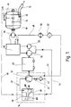
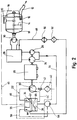
- the mixing and conveying devices shown schematically in the drawing essentially consist of a mixing vessel 18 that can be filled with mixed material via the closable filling opening 10, is connected to a conveying line 12, contains an agitator 14 and can be pressurized with compressed air via the openings 16, and is preferably designed as a diesel engine Drive motor 20, a screw compressor 22 which can be driven by the drive motor for generating the compressed air, and two hydraulic pumps 24, 26 which are driven jointly by the drive motor 20 and which operate via a hydraulic control block 28 act on a hydraulic motor 30 for driving the agitator 14 with pressure oil.
- the screw compressor 22 comprises a screw compressor 32 and an oil / air container 34 with a compressed air separator 36 and an oil sump 38.
- the screw compressor 32 can be supplied with atmospheric air via an air filter 40 and a shut-off throttle valve 42 and with lubricating and cooling oil via an injection line 44, 44 ' .
- the oil / air mixture emerging from the screw compressor under a pressure of 5 to 7 bar reaches the oil / air container 34 via a channel or a line 46.
- compressed air reaches the air inlet openings 16 via the air separator 36 and the compressed air line 46 and promotes this Mixing and conveyed material located in the mixing container 18 plugs out through the conveying line 12.
- the hydraulic circuit leading to the hydraulic pump 30 and the lubricating and cooling oil circuit of the screw compressor are jointly supplied with oil from the oil sump 38 of the oil / air container. Likewise, only one oil cooler 50 and one oil filter 52 are provided for both oil circuits.
- the low-pressure side of the hydraulic pumps 24, 26 is connected directly to the oil sump 38 via the supply line 54, while in the exemplary embodiment according to FIG. 2 a pre-compressor pump 56 is arranged in the supply line 54, in which the oil flows out the oil sump 38 pre-compressed to a pressure of about 30 bar and thereby from the air contained therein is freed.
- the compressed air separated in the pre-compressor 56 is returned to the oil / air tank via line 58.
- Another difference between the two exemplary embodiments is that the oil arriving via the return line 48, the cooler 50 and the filter 52 in the case of FIG. 1 via the line 44 to the oil injection point of the screw compressor 32 and in the case of FIG. 2 in the Oil sump 38 of the oil / air tank is passed.
- the oil injection line 44 'leading to the screw compressor is branched off directly from the oil sump 38 of the oil / air container 34.
- a cooler 50 'and an oil filter 52' are additionally arranged in the oil injection line 44 'branched off from the oil sump 38.
- the oil sump is divided into an inlet zone 60 and an outlet zone 62 by an air separator 64 or a bulkhead. It is thereby achieved that the air-laden oil coming into the oil / air container via the lines 46 and 48 is degassed at the air separating screen 64 or the bulkhead, so that the exit zone 62, to which the lines 44, 44 'and 54 are connected, contains largely gas-free oil.
- the invention relates to a mixing and compressed air conveying device, in particular for mortar or concrete as mixed and conveyed material, with a material that can be fed with the mixed and conveyed material, connected to a conveying line 12, and contains a motor-driven agitator 14 Mixing tank 18 which can be pressurized with compressed air, a drive motor 20 and a screw compressor 32 which can be driven by the drive motor for generating the compressed air.
- the agitator can be driven by means of a hydraulic motor 30 which can be pressurized with pressure oil via at least one hydraulic pump 24, 26 driven by the drive motor 20.
- the screw compressor 32 is arranged in a lubricating and cooling oil circuit containing an oil / air container 34 with an air separator 36 and an oil sump 38.
- the hydraulic circuit of the agitator drive and the lubricating and cooling oil circuit of the screw compressor 32 have a common oil tank formed by the oil sump 38 of the oil / air container and a common oil cooler 50 and oil filter 52.
Landscapes
- Engineering & Computer Science (AREA)
- Mechanical Engineering (AREA)
- Structural Engineering (AREA)
- Supply Devices, Intensifiers, Converters, And Telemotors (AREA)
- Fluid-Pressure Circuits (AREA)
- Refuse Collection And Transfer (AREA)
- Preparation Of Clay, And Manufacture Of Mixtures Containing Clay Or Cement (AREA)
- On-Site Construction Work That Accompanies The Preparation And Application Of Concrete (AREA)
- Nozzles (AREA)
Description
- Die Erfindung betrifft ein Misch- und Druckluftfördergerät, insbesondere für Mörtel oder Beton als Misch- und Fördergut, mit einem mit dem Misch- und Fördergut beschickbaren, an eine Förderleitung angeschlossenen, ein motorisch angetriebenes Rührwerk enthaltenden und mit Druckluft beaufschlagbaren Mischkessel, einem Antriebsmotor und einem durch den Antriebsmotor antreibbaren Schraubenverdichter für die Erzeugung der Druckluft, wobei das Rührwerk mittels eines Hydromotors antreibbar ist, der über mindestens eine durch den Antriebsmotor angetriebene Hydropumpe mit Drucköl beaufschlagbar und zusammen mit diesem in einem einen Ölkühler und einen Ölfilter enthaltenden Hydraulikkreis angeordnet ist, und wobei der Schraubenverdichter in einem einen Öl/Luftbehälter mit Luftabscheider und Ölsumpf, einen Ölkühler und einen Ölfilter enthaltenden Schmier- und Kühlölkreis angeordnet ist.
- Misch- und Druckluftfördergeräte dieser Art dienen in der Bauindustrie zur Mischung und Förderung von Dickstoffen, wie Mörtel, Estrich, Beton oder dergleichen. Das beispielsweise aus Sand und einem Bindemittel bestehende Mischgut wird unter Wasserzugabe über eine Einfüllöffnung dem Mischkessel zugeführt. Dort wird bei laufendem Rührwerk das Mischgut gründlich durchgemischt. Zur Förderung wird nach Fertigstellung der Mischung der Deckel des Mischkessels geschlossen und komprimierte Luft über den Schraubenverdichter dem Mischkessel zugeführt. Unter der Einwirkung der Druckluft wird das Misch- und Fördergut in Form von durch Druckluftpolster voneinander getrennten Pfropfen durch die Förderleitung gefördert. Die hydraulische Kraftübertragung zwischen Antriebsmotor und Rührwerk bringt wegen der Verschleißfreiheit erhebliche Vorteile sowohl in der Standzeit als auch bei der Realisierbarkeit eines hydraulisch geregelten Überlastschutzes für Motoren und Mischer mit sich (EP 367 912 A1). Andererseits ist hierfür ein Hydraulikkreis mit relativ aufwendigen Bauteilen, wie Öltank, Ölfilter und Ölkühler erforderlich. Weiter enthalten die bekannten Misch- und Druckluftförderer üblicherweise einen Schraubenverdichter mit Öleinspritzkühlung und -schmierung. Der Schraubenverdichter ist zu diesem Zweck in einem Schmier- und Kühlölkreislauf angeordnet, der u.a. einen Öl/Luftbehälter mit Luftabscheider und Ölsumpf, einen Ölfilter und einen Ölkühler enthält.
- Ausgehend hiervon liegt der Erfindung die Aufgabe zugrunde, das bekannte Misch- und Druckluftfördergerät der eingangs angegebenen Art dahingehend zu verbessern daß eine leichtere Bauweise, ein geringerer Montage- und Verrohrungsaufwand und ein geringerer Wartungsaufwand erzielt werden kann.
- Zur Lösung dieser Aufgabe wird die im Patentanspruch 1 angegebene Merkmalskombination vorgeschlagen. Vorteilhafte Ausgestaltungen und Weiterbildungen der Erfindung ergeben sich aus den Unteransprüchen.
- Die erfindungsgemäße Lösung geht von dem Gedanken aus, daß der Hydraulikkreis des Rührwerkantriebs und der Schmier- und Kühlölkreis des Schraubenverdichters trotz der grundsätzlich verschiedenen Aufgaben zu einem einheitlichen Hydrauliksystem zusammengefaßt werden können. Um dies zu erreichen, wird gemäß der Erfindung vorgeschlagen, daß der Hydraulikkreis des Rührwerkantriebs und der Schmier- und Kühlölkreis des Schraubenverdichters einen gemeinsamen Öltank aufweisen, der vorzugsweise durch den Ölsumpf des Öl/Luftbehälters gebildet ist. Eine weitere Vereinfachung in dieser Hinsicht wird dadurch erzielt, daß der Hydraulikkreis und der Schmier- und Kühlölkreis auch einen gemeinsamen Ölfilter und/oder Ölkühler aufweisen.
- Eine bevorzugte Ausgestaltung der Erfindung sieht vor, daß die Hydropumpe des Rührwerkantriebs saugseitig unmittelbar oder über eine Vorverdichterpumpe mit Öl aus dem Ölsumpf des Öl/Luftbehälters des Schraubenverdichters beaufschlagbar ist. Bei Verwendung einer Vorverdichterpumpe wird etwaige Luft, die im angesaugten Öl noch enthalten ist, abgeschieden, bevor das Öl der Hydraulikpumpe zugeführt wird. Mit der Vorverdichterpumpe wird das Hydrauliköl auf beispielsweise 30 bar vorverdichtet und dabei die in ihm enthaltende Luft abgeschieden. Die abgeschiedene Luft kann über eine Druckluftleitung in den Öl/Luftbehälter zurückgeführt werden. Zur Verbesserung der Luftabscheidung kann im Öl/Luftbehälter zusätzlich mindestens eine Luftabscheidestufe vorgesehen werden, die aus Lochblechen bestehen kann, von denen auch mehrere hintereinander im Öl/Luftbehälter angeordnet werden können. Der Schraubenblock des Schraubenverdichters kann entweder integrierter oder separater Bestandteil des Öl/Luftbehälters sein.
- Für den Fall, daß das Hydrauliköl für die Antriebshydraulik noch zu viel Luft enthalten sollte, können dem Hydrauliköl auch an sich bekannte Chemikalien zugesetzt werden, die dafür sorgen, daß die noch vorhandene Luft entfernt oder in geeigneter Weise gebunden wird. Andererseits ist es auch denkbar, für den Antriebshydraulikkreis luftresistente Hydraulikaggregate und Armaturen auszuwählen.
- Gemäß einer weiteren vorteilhaften Ausgestaltung der Erfindung ist der Hydromotor des Rührwerkantriebs rückflußseitig über den Ölkühler und Ölfilter nach Art einer Serienschaltung mit dem Schmier- und Öleintritt des Schraubenverdichters verbunden.
- Alternativ dazu kann der Hydromotor des Rührwerkantriebs unmittelbar oder mittelbar über den Ölfilter und/oder Ölkühler in den Öl/Luftbehälter münden, während der Schraubenverdichter unmittelbar oder mittelbar über einen weiteren Ölkühler und/oder Ölfilter aus dem Ölsumpf des Öl/Luftbehälters mit Schmier- und Kühlöl beaufschlagbar ist. Grundsätzlich ist es auch möglich, daß der Hydromotor des Rührwerkantriebs rückflußseitig unmittelbar in den Öl/Luftbehälter mündet, während der Schraubenverdichter aus dem Ölsumpf des Öl/Luftbehälters unter Zwischenschaltung des Ölfilters und/oder Ölkühlers mit Schmier- und Kühlöl beaufschlagbar ist.
- Im folgenden wird die Erfindung anhand der in der Zeichnung in schematischer Weise dargestellten Ausführungsbeispiele näher erläutert. Es zeigen
- Fig. 1
- ein hydraulisches Schaltschema eines Misch- und Druckluftfördergeräts;
- Fig. 2
- ein hydraulisches Schaltschema eines gegenüber Fig. 1 abgewandelten Misch- und Druckluftfördergeräts;
- Fig. 3
- ein hydraulisches Schaltschema eines weiteren, gegenüber Fig. 1 abgewandelten Misch- und Druckluftfördergeräts.
- Die in der Zeichnung schematisch dargestellten Misch- und Fördergeräte bestehen im wesentlichen aus einem über die verschließbare Einfüllöffnung 10 mit Mischgut beschickbaren, an eine Förderleitung 12 angeschlossenen, ein Rührwerk 14 enthaltenden und über die Öffnungen 16 mit Druckluft beaufschlagbaren Mischkessel 18, einem vorzugsweise als Dieselmotor ausgebildeten Antriebsmotor 20, einem durch den Antriebsmotor antreibbaren Schraubenkompressor 22 für die Erzeugung der Druckluft sowie zwei gemeinsam durch den Antriebsmotor 20 angetriebenen Hydropumpen 24,26, die über einen Hydraulik-Steuerblock 28 einen Hydromotor 30 für den Antrieb des Rührwerks 14 mit Drucköl beaufschlagen. Der Schraubenkompressor 22 umfaßt einen Schraubenverdichter 32 und einen Öl/Luftbehälter 34 mit Druckluftabscheider 36 und Ölsumpf 38. Der Schraubenverdichter 32 ist saugseitig über ein Luftfilter 40 und eine absperrbare Drosselklappe 42 mit Atmosphärenluft und über eine Einspritzleitung 44,44' mit Schmier- und Kühlöl beaufschlagbar. Das aus dem Schraubenverdichter unter einem Druck von 5 bis 7 bar austretende Öl/Luftgemisch gelangt über einen Kanal oder eine Leitung 46 in den Öl/Luftbehälter 34. Beim Fördervorgang gelangt Druckluft über den Luftabscheider 36 und die Druckluftleitung 46 zu den Lufteintrittsoffnungen 16 und fördert das im Mischbehälter 18 befindliche Misch- und Fördergut propfenweise durch die Förderleitung 12 nach außen.
- Der zur Hydropumpe 30 führende Hydraulikkreis und der Schmier- und Kühlolkreis des Schraubenkompressors werden gemeinsam aus dem Ölsumpf 38 des Öl/Luftbehälters mit Öl versorgt. Ebenso ist nur ein Ölkühler 50 und ein Ölfilter 52 für beide Ölkreise vorgesehen.
- Bei dem in Fig. 1 gezeigten Ausführungsbeispiel ist die Niederdruckseite der Hydropumpen 24,26 unmittelbar über die Versorgungsleitung 54 mit dem Ölsumpf 38 verbunden, während bei dem Ausführungsbeispiel nach Fig. 2 in der Versorgungsleitung 54 eine Vorverdichterpumpe 56 angeordnet ist, in der das Öl aus dem Ölsumpf 38 auf einen Druck von ca. 30 bar vorverdichtet und dabei von der darin noch enthaltenen Luft befreit wird. Die im Vorverdichter 56 abgeschiedene Druckluft wird über die Leitung 58 in den Öl/Luftbehälter zurückgeführt.
- Ein weiterer Unterschied zwischen den beiden Ausführungsbeispielen besteht darin, daß das über die Rücklaufleitung 48, den Kühler 50 und den Filter 52 ankommende Öl im Falle der Fig. 1 über die Leitung 44 zur Öleinspritzstelle des Schraubenverdichters 32 und im Falle der Fig. 2 in den Ölsumpf 38 des Öl/Luftbehälters geleitet wird. Im letzteren Falle ist die zum Schraubenverdichter führende Öleinspritzleitung 44' unmittelbar vom Ölsumpf 38 des Öl/Luftbehälters 34 abgezweigt.
- Bei dem in Fig. 3 gezeigten Ausführungsbeispiel ist in der vom Ölsumpf 38 abgezweigten Öleinspritzleitung 44' zusätzlich ein Kühler 50' und ein Ölfilter 52' angeordnet.
- Um zu gewährleisten, daß aus dem Ölsumpf weitgehend gasfreies Öl abgezweigt wird, ist der Ölsumpf durch einen Luftabscheider 64 oder eine Schottwand in eine Eingangszone 60 und eine Ausgangszone 62 unterteilt. Dadurch wird erreicht, daß das über die Leitungen 46 und 48 in den Öl/Luftbehälter gelangende, luftbeladene Öl am Luftabscheidesieb 64 bzw. der Schottwand entgast wird, so daß die Ausgangszone 62, an die die Leitungen 44,44' und 54 angeschlossen sind, weitgehend gasfreies Öl enthält.
- Zusammenfassend ist folgendes festzustellen: Die Erfindung bezieht sich auf ein Misch- und Druckluftfördergerät, insbesondere für Mörtel oder Beton als Misch- und Fördergut, mit einem mit dem Misch- und Fördergut beschickbaren, an eine Förderleitung 12 angeschlossenen, ein motorisch angetriebenes Rührwerk 14 enthaltenden und mit Druckluft beaufschlagbaren Mischkessel 18, einem Antriebsmotor 20 und einem durch den Antriebsmotor antreibbaren Schraubenverdichter 32 für die Erzeugung der Druckluft. Das Rührwerk ist mittels eines Hydromotors 30 antreibbar, der über mindestens eine durch den Antriebsmotor 20 angetriebene Hydropumpe 24,26 mit Drucköl beaufschlagbar ist. Der Schraubenverdichter 32 ist in einem einen Öl/Luftbehälter 34 mit Luftabscheider 36 und Ölsumpf 38 enthaltenden Schmier- und Kühlölkreis angeordnet. Um eine leichte Bauweise und eine einfache Montage und Wartung zu gewährleisten, weisen der Hydraulikkreis des Rührwerkantriebs und der Schmier- und Kühlölkreis des Schraubenverdichters 32 einen gemeinsamen, durch den Ölsumpf 38 des Öl/Luftbehälters gebildeten Öltank sowie einen gemeinsamen Ölkühler 50 und Ölfilter 52 auf.
Claims (8)
- Misch- und Druckluftfördergerät, insbesondere für Mörtel oder Beton als Misch- und Fördergut mit einem mit dem Misch- und Fördergut beschickbaren, an eine Förderleitung (12) angeschlossenen, ein motorisch angetriebenes Rührwerk (14) enthaltenden und mit Druckluft (16,46) beaufschlagbaren Mischkessel, einem Antriebsmotor (20) und einem durch den Antriebsmotor antreibbaren Schraubenverdichter (32) für die Erzeugung der Druckluft, wobei das Rührwerk (14) mittels eines Hydromotors (30) antreibbar ist, der über mindestens eine durch den Antriebsmotor (20) angetriebene Hydropumpe (24,26) mit Drucköl beaufschlagbar und zusammen mit diesem in einem einen Öltank (38), einen Ölkühler (50) und einen Ölfilter (52) enthaltenden Hydraulikkreis angeordnet ist, und wobei der Schraubenverdichter (32) in einem einen Öl/Luftbehälter (34) mit Luftabscheider (36) und Ölsumpf (38), einen Ölkühler (50) und einen Ölfilter (52) enthaltenden Schmier- und Kühlölkreis angeordnet ist, dadurch gekennzeichnet, daß der Hydraulikkreis (24,26,28,30) des Rührwerkantriebs und der Schmier- und Kühlölkreis des Schraubenverdichters (32) einen gemeinsamen, durch den Ölsumpf (38) des Öl/Luftbehälters (34) gebildeten Öltank aufweisen.
- Misch- und Druckluftfördergerät nach Anspruch 1, dadurch gekennzeichnet, daß der Hydraulikkreis (24, 26,28,30) des Rührwerkantriebs und der Schmier- und Kühlölkreis des Schraubenverdichters (32) einen gemeinsamen Ölkühler (50) und/oder Ölfilter (52) aufweisen.
- Misch- und Druckluftfördergerät nach Anspruch 1 oder 2, dadurch gekennzeichnet, daß die Hydropumpe (24,26) des Rührwerkantriebs saugseitig unmittelbar oder über eine Vorverdichterpumpe (56) mit Öl aus dem Ölsumpf (38) des Öl/Luftbehälters des Schraubenverdichters (32) beaufschlagbar ist.
- Misch- und Druckluftfördergerät nach Anspruch 3, dadurch gekennzeichnet, daß die Vorverdichterpumpe (56) einen Luftabscheider mit einer in den Öl/Luftbehälter (34) zurückgeführten Druckluftleitung (58) aufweist.
- Misch- und Druckluftfördergerät nach einem der Ansprüche 1 bis 4, dadurch gekennzeichnet, daß der Hydromotor (30) des Rührwerkantriebs rückflußseitig über den Ölkühler (50) und den Ölfilter (52) mit dem Schmier- und Kühlöleintritt des Schraubenverdichters (32) verbunden ist.
- Misch- und Druckluftfördergerät nach einem der Ansprüche 1 bis 4, dadurch gekennzeichnet, daß der Hydromotor (30) des Rührwerkantriebs rückflußseitig unmittelbar oder mittelbar über den Ölkühler (50) und/oder den Ölfilter (52) in den Öl/Luftbehälter (34) mündet und daß der Schraubenverdichter (32) unmittelbar oder mittelbar über einen weiteren Ölkühler und/oder Ölfilter aus dem Ölsumpf (38) des Öl/Luftbehälters (34) mit Schmier- und Kühlöl beaufschlagbar ist.
- Misch- und Fördergerät nach einem der Ansprüche 1 bis 6, dadurch gekennzeichnet, daß der Ölsumpf (38) des Öl/Luftbehälters (34) in eine Eingangszone (60) mit gasbeladenem Öl und eine Ausgangszone (62) mit entgastem Öl unterteilt ist.
- Misch- und Fördergerät nach Anspruch 7, dadurch gekennzeichnet, daß die Eingangszone (60) und die Ausgangszone (62) durch ein in den Ölsumpf eintauchendes Luftabscheidesieb (64) oder eine entsprechende Schottwand flüssigkeitsdurchlässig voneinander getrennt sind.
Applications Claiming Priority (3)
| Application Number | Priority Date | Filing Date | Title |
|---|---|---|---|
| DE4211139 | 1992-04-03 | ||
| DE4211139A DE4211139A1 (de) | 1992-04-03 | 1992-04-03 | Misch- und Druckluftfördergerät |
| PCT/EP1993/000764 WO1993019914A1 (de) | 1992-04-03 | 1993-03-30 | Misch- und druckluftfördergerät |
Publications (2)
| Publication Number | Publication Date |
|---|---|
| EP0633831A1 EP0633831A1 (de) | 1995-01-18 |
| EP0633831B1 true EP0633831B1 (de) | 1996-09-11 |
Family
ID=6455935
Family Applications (1)
| Application Number | Title | Priority Date | Filing Date |
|---|---|---|---|
| EP93907853A Expired - Lifetime EP0633831B1 (de) | 1992-04-03 | 1993-03-30 | Misch- und druckluftfördergerät |
Country Status (4)
| Country | Link |
|---|---|
| EP (1) | EP0633831B1 (de) |
| AT (1) | ATE142553T1 (de) |
| DE (2) | DE4211139A1 (de) |
| WO (1) | WO1993019914A1 (de) |
Families Citing this family (6)
| Publication number | Priority date | Publication date | Assignee | Title |
|---|---|---|---|---|
| EP1120216B1 (de) | 2000-01-27 | 2006-05-24 | Kaeser Kompressoren GmbH | Verfahren und Vorrichtung zum Mischen und Fördern von Beton |
| JP5649177B2 (ja) * | 2011-03-24 | 2015-01-07 | カヤバ工業株式会社 | ミキサドラム駆動装置 |
| CN103174652B (zh) * | 2013-03-09 | 2015-08-12 | 宁德市优力维特电梯配件有限公司 | 一种螺杆空压机及其配套稀土永磁电机 |
| CN106738317A (zh) * | 2016-12-13 | 2017-05-31 | 顾广才 | 一种高效水泥搅拌装置 |
| DE102017104780A1 (de) * | 2017-03-07 | 2018-09-13 | Putzmeister Engineering Gmbh | Druckloser Mischer mit Fördereinrichtung |
| CN114604088A (zh) * | 2022-03-31 | 2022-06-10 | 宁波英德菲尔机械科技有限公司 | 安装于车载罐体的空气压缩机组合和车载罐体 |
Family Cites Families (8)
| Publication number | Priority date | Publication date | Assignee | Title |
|---|---|---|---|---|
| FR1240836A (fr) * | 1958-11-07 | 1960-09-09 | Ready Mixed Concrete Ltd | Installation de transmission de force hydraulique |
| US3209850A (en) * | 1963-02-26 | 1965-10-05 | Gen Dynamics Corp | Trailer having longitudinally adjustable and driven rear wheels |
| FR1374358A (fr) * | 1963-05-22 | 1964-10-09 | Richier Sa | Installation de malaxage à cuve fixe |
| DE2302752C3 (de) * | 1973-01-20 | 1982-01-28 | Zahnradfabrik Friedrichshafen Ag, 7990 Friedrichshafen | Ringtrog-Zwangsmischer |
| DE3013373C2 (de) * | 1980-04-05 | 1986-09-11 | Karl Dipl.-Ing. 7000 Stuttgart Schlecht | Misch- und Fördergerät |
| DE8430087U1 (de) * | 1984-10-12 | 1985-01-10 | TEKA Maschinenbau GmbH, 6732 Edenkoben | Vorrichtung zum einfuehren von leitungen in ringtrogmischer |
| DE3624832A1 (de) * | 1986-07-23 | 1988-01-28 | Teka Maschinenbau Gmbh | Vorrichtung zum antreiben eines zwangsmischers |
| DE3836930A1 (de) * | 1988-10-29 | 1990-05-03 | Putzmeister Maschf | Misch- und druckluftfoerdergeraet |
-
1992
- 1992-04-03 DE DE4211139A patent/DE4211139A1/de not_active Withdrawn
-
1993
- 1993-03-30 AT AT93907853T patent/ATE142553T1/de not_active IP Right Cessation
- 1993-03-30 DE DE59303765T patent/DE59303765D1/de not_active Expired - Fee Related
- 1993-03-30 WO PCT/EP1993/000764 patent/WO1993019914A1/de not_active Ceased
- 1993-03-30 EP EP93907853A patent/EP0633831B1/de not_active Expired - Lifetime
Also Published As
| Publication number | Publication date |
|---|---|
| ATE142553T1 (de) | 1996-09-15 |
| WO1993019914A1 (de) | 1993-10-14 |
| DE59303765D1 (de) | 1996-10-17 |
| DE4211139A1 (de) | 1993-10-07 |
| EP0633831A1 (de) | 1995-01-18 |
Similar Documents
| Publication | Publication Date | Title |
|---|---|---|
| DE2600488A1 (de) | Verfahren und vorrichtung zur ableitung von in einem an das hochdruckende eines kompressors mit fluessigkeitseinspritzung angeschlossenen nachabscheider abgeschiedener fluessigkeit | |
| DE102004046316A1 (de) | Verfahren und Vorrichtung zum Verdichten eines gasförmigen Mediums | |
| DE3100443A1 (de) | Verfahren und vorrichtung zur herstellung und gegebenenfalls foerderung von aufgeschaeumten gemischen aus bindemitteln oder bindemitteln mit zuschlagstoffen | |
| DE4210687A1 (de) | Vorrichtung für die Abgabe zähflüssiger, aushärtender Stoffe, sowie Verfahren zum Betrieb einer derartigen Vorrichtung | |
| DE3127831A1 (de) | "system und vorrichtung zum pumpen" | |
| EP1194694B2 (de) | Vorrichtung zum pumpen grosser fördermengen einer flüssigkeit | |
| DE2736153A1 (de) | Filter- und mischeinrichtung zur vermischung von schmieroel und kraftstoff | |
| EP0633831A1 (de) | Misch- und druckluftfördergerät. | |
| DE3310663C2 (de) | Hochdruckreinigungsgerät | |
| EP3942181A1 (de) | Mobile dickstoffpumpe | |
| DE19848234A1 (de) | Verfahren und Verdichter zum Komprimieren von Gasen | |
| DE2507580A1 (de) | Vorrichtung zum zufuehren fliessfaehigen materials unter druck | |
| DE10115233A1 (de) | Horizontalbohranlage | |
| DE3013373C2 (de) | Misch- und Fördergerät | |
| DE102018209202B4 (de) | Fluidstromgenerator, Fördervorrichtung und Transportfahrzeug | |
| EP0102603B1 (de) | Vorrichtung für die Zufuhr von fein verteilter Flüssigkeit | |
| DE3400659C1 (de) | Drehkolbenschieber fuer pneumatische Setzmaschinen | |
| DE202007011666U1 (de) | Vorrichtung zum Mischen von Polyurethan o.dgl. Mehrkomponentenkunststoffen | |
| EP0662875B1 (de) | Misch- und fördergerät | |
| DE3004846C2 (de) | Verfahren zur schnellen, unmittelbaren reversiblen Mengenänderung de Wirbelschichtmasse einer Wirbelschichtfeuerung | |
| DE102004045123B3 (de) | Vorrichtung zur Erzeugung von Druckluft mit einer Kompressoranordnung | |
| DE3021071A1 (de) | Verfahren zum herstellen eines fluessigen verbrennungsmaterials | |
| EP0540892B1 (de) | Wechselbehälter mit Misch-Einsatz | |
| AT223926B (de) | Verfahren zur Herstellung von mit Kohlensäure imprägnierten Getränken und Anlage zur Durchführung des Verfahrens | |
| EP1095673A2 (de) | Zumischeinrichtung für Feuerlöschanlagen |
Legal Events
| Date | Code | Title | Description |
|---|---|---|---|
| PUAI | Public reference made under article 153(3) epc to a published international application that has entered the european phase |
Free format text: ORIGINAL CODE: 0009012 |
|
| 17P | Request for examination filed |
Effective date: 19940915 |
|
| AK | Designated contracting states |
Kind code of ref document: A1 Designated state(s): AT CH DE ES FR GB IT LI NL |
|
| 17Q | First examination report despatched |
Effective date: 19951109 |
|
| GRAH | Despatch of communication of intention to grant a patent |
Free format text: ORIGINAL CODE: EPIDOS IGRA |
|
| GRAH | Despatch of communication of intention to grant a patent |
Free format text: ORIGINAL CODE: EPIDOS IGRA |
|
| GRAA | (expected) grant |
Free format text: ORIGINAL CODE: 0009210 |
|
| AK | Designated contracting states |
Kind code of ref document: B1 Designated state(s): AT CH DE ES FR GB IT LI NL |
|
| PG25 | Lapsed in a contracting state [announced via postgrant information from national office to epo] |
Ref country code: NL Free format text: LAPSE BECAUSE OF FAILURE TO SUBMIT A TRANSLATION OF THE DESCRIPTION OR TO PAY THE FEE WITHIN THE PRESCRIBED TIME-LIMIT Effective date: 19960911 Ref country code: GB Effective date: 19960911 Ref country code: ES Free format text: THE PATENT HAS BEEN ANNULLED BY A DECISION OF A NATIONAL AUTHORITY Effective date: 19960911 |
|
| REF | Corresponds to: |
Ref document number: 142553 Country of ref document: AT Date of ref document: 19960915 Kind code of ref document: T |
|
| REF | Corresponds to: |
Ref document number: 59303765 Country of ref document: DE Date of ref document: 19961017 |
|
| ET | Fr: translation filed | ||
| ITF | It: translation for a ep patent filed | ||
| NLV1 | Nl: lapsed or annulled due to failure to fulfill the requirements of art. 29p and 29m of the patents act | ||
| GBV | Gb: ep patent (uk) treated as always having been void in accordance with gb section 77(7)/1977 [no translation filed] |
Effective date: 19960911 |
|
| PG25 | Lapsed in a contracting state [announced via postgrant information from national office to epo] |
Ref country code: AT Free format text: LAPSE BECAUSE OF NON-PAYMENT OF DUE FEES Effective date: 19970330 |
|
| PG25 | Lapsed in a contracting state [announced via postgrant information from national office to epo] |
Ref country code: LI Effective date: 19970331 Ref country code: CH Effective date: 19970331 |
|
| RAP2 | Party data changed (patent owner data changed or rights of a patent transferred) |
Owner name: PUTZMEISTER AKTIENGESELLSCHAFT |
|
| PLBE | No opposition filed within time limit |
Free format text: ORIGINAL CODE: 0009261 |
|
| STAA | Information on the status of an ep patent application or granted ep patent |
Free format text: STATUS: NO OPPOSITION FILED WITHIN TIME LIMIT |
|
| 26N | No opposition filed | ||
| REG | Reference to a national code |
Ref country code: CH Ref legal event code: PL |
|
| PGFP | Annual fee paid to national office [announced via postgrant information from national office to epo] |
Ref country code: FR Payment date: 20030211 Year of fee payment: 11 |
|
| PGFP | Annual fee paid to national office [announced via postgrant information from national office to epo] |
Ref country code: DE Payment date: 20030326 Year of fee payment: 11 |
|
| PG25 | Lapsed in a contracting state [announced via postgrant information from national office to epo] |
Ref country code: DE Free format text: LAPSE BECAUSE OF NON-PAYMENT OF DUE FEES Effective date: 20041001 |
|
| PG25 | Lapsed in a contracting state [announced via postgrant information from national office to epo] |
Ref country code: FR Free format text: LAPSE BECAUSE OF NON-PAYMENT OF DUE FEES Effective date: 20041130 |
|
| REG | Reference to a national code |
Ref country code: FR Ref legal event code: ST |
|
| PG25 | Lapsed in a contracting state [announced via postgrant information from national office to epo] |
Ref country code: IT Free format text: LAPSE BECAUSE OF NON-PAYMENT OF DUE FEES;WARNING: LAPSES OF ITALIAN PATENTS WITH EFFECTIVE DATE BEFORE 2007 MAY HAVE OCCURRED AT ANY TIME BEFORE 2007. THE CORRECT EFFECTIVE DATE MAY BE DIFFERENT FROM THE ONE RECORDED. Effective date: 20050330 |