EP0632953A2 - Machine pour le travail du sol - Google Patents
Machine pour le travail du sol Download PDFInfo
- Publication number
- EP0632953A2 EP0632953A2 EP94109538A EP94109538A EP0632953A2 EP 0632953 A2 EP0632953 A2 EP 0632953A2 EP 94109538 A EP94109538 A EP 94109538A EP 94109538 A EP94109538 A EP 94109538A EP 0632953 A2 EP0632953 A2 EP 0632953A2
- Authority
- EP
- European Patent Office
- Prior art keywords
- frame
- tractor
- force
- tools
- soil cultivation
- Prior art date
- Legal status (The legal status is an assumption and is not a legal conclusion. Google has not performed a legal analysis and makes no representation as to the accuracy of the status listed.)
- Granted
Links
- 239000002689 soil Substances 0.000 title claims description 39
- 238000003971 tillage Methods 0.000 claims description 48
- 230000005540 biological transmission Effects 0.000 claims description 14
- 238000009331 sowing Methods 0.000 description 16
- 239000003337 fertilizer Substances 0.000 description 8
- 239000012530 fluid Substances 0.000 description 5
- 238000005056 compaction Methods 0.000 description 3
- 230000035515 penetration Effects 0.000 description 3
- 239000004575 stone Substances 0.000 description 3
- 238000000418 atomic force spectrum Methods 0.000 description 2
- 230000015572 biosynthetic process Effects 0.000 description 2
- 230000001154 acute effect Effects 0.000 description 1
- 230000000712 assembly Effects 0.000 description 1
- 238000000429 assembly Methods 0.000 description 1
- 238000013016 damping Methods 0.000 description 1
- 230000007423 decrease Effects 0.000 description 1
- 230000003628 erosive effect Effects 0.000 description 1
- 230000010355 oscillation Effects 0.000 description 1
- 239000011814 protection agent Substances 0.000 description 1
- 238000009420 retrofitting Methods 0.000 description 1
- XLYOFNOQVPJJNP-UHFFFAOYSA-N water Substances O XLYOFNOQVPJJNP-UHFFFAOYSA-N 0.000 description 1
Images

Classifications
-
- A—HUMAN NECESSITIES
- A01—AGRICULTURE; FORESTRY; ANIMAL HUSBANDRY; HUNTING; TRAPPING; FISHING
- A01B—SOIL WORKING IN AGRICULTURE OR FORESTRY; PARTS, DETAILS, OR ACCESSORIES OF AGRICULTURAL MACHINES OR IMPLEMENTS, IN GENERAL
- A01B59/00—Devices specially adapted for connection between animals or tractors and agricultural machines or implements
- A01B59/06—Devices specially adapted for connection between animals or tractors and agricultural machines or implements for machines mounted on tractors
- A01B59/066—Devices specially adapted for connection between animals or tractors and agricultural machines or implements for machines mounted on tractors of the type comprising at least two lower arms and one upper arm generally arranged in a triangle (e.g. three-point hitches)
- A01B59/067—Devices specially adapted for connection between animals or tractors and agricultural machines or implements for machines mounted on tractors of the type comprising at least two lower arms and one upper arm generally arranged in a triangle (e.g. three-point hitches) the lower arms being lifted or lowered by power actuator means internally incorporated in the tractor
-
- A—HUMAN NECESSITIES
- A01—AGRICULTURE; FORESTRY; ANIMAL HUSBANDRY; HUNTING; TRAPPING; FISHING
- A01B—SOIL WORKING IN AGRICULTURE OR FORESTRY; PARTS, DETAILS, OR ACCESSORIES OF AGRICULTURAL MACHINES OR IMPLEMENTS, IN GENERAL
- A01B63/00—Lifting or adjusting devices or arrangements for agricultural machines or implements
- A01B63/02—Lifting or adjusting devices or arrangements for agricultural machines or implements for implements mounted on tractors
- A01B63/10—Lifting or adjusting devices or arrangements for agricultural machines or implements for implements mounted on tractors operated by hydraulic or pneumatic means
- A01B63/11—Lifting or adjusting devices or arrangements for agricultural machines or implements for implements mounted on tractors operated by hydraulic or pneumatic means for controlling weight transfer between implements and tractor wheels
Definitions
- the invention relates to a tillage machine that can be attached to a tractor, in particular a seed drill, with a frame and a plurality of tillage tools mounted on the frame, a four-axis link arrangement with lower link arms of the tractor that can be raised in parallel and an overlying one arranged between the frame and the tractor. pivotable upper link is provided.
- the soil tillage machine is understood to mean any device with soil tillage tools which engage in the soil or otherwise work on the soil.
- the extent to which sawdust, fertilizer, crop protection agents or the like are applied to the soil or introduced into the soil is immaterial. It is only important that the soil cultivation tools are put up with a resistance. This resistance acts on the frame via the tillage tools.
- the present invention deals with the problem area of direct sowing, i. H. the introduction of sawdust into unprocessed or only slightly pre-processed soils. At least with direct sowing, there is no plowing of the soil before the seed is brought in. In this way, both the natural soil structure inside the soil and the soil surface stabilized, for example, by root formation, are preserved.
- the stabilized surface structure shows a significantly improved resistance to wind and water erosion compared to soil prepared by plowing for sowing seeds.
- the omitted plowing step naturally also reduces the total labor and energy required when ordering the soils.
- a seed drill of the type described at the outset to provide generously dimensioned force transmitters for a restoring force between the electrode processing tools and the frame.
- the tillage tools are mounted in groups on the frame via parallelogram link arrangements and can be pivoted upwards against the restoring force between the tillage tools and the frame.
- the force transmitters act on the parallelogram linkage arrangements to produce the restoring forces between the frame and the tillage tools.
- Each group of tillage tools includes a sowing unit with a rotating coulter, a support wheel that determines the maximum penetration depth of the coulter into the ground and a closing wheel downstream of the coulter Press the seed furrow again.
- a coil spring which is arranged between the respective upper links and the respective lower links, acts as a force generator and causes the restoring force between the frame and the tillage tools, which acts on the soil tillage tools.
- the forces that can be provided in this way are limited, however, since they must be taken up by the frame in the sum of all the tools and push it upwards.
- the frame has only its own weight and the lifting resistance of the four-axle handlebar arrangement between the tractor and the frame to counteract the upward force. This sets narrow limits for the restoring forces that can be provided between the frame and the tools.
- the spiral spring has a comparatively unfavorable path-force curve.
- the restoring force exerted by the spring increases. This increases the risk of the tools being damaged by the stone.
- the restoring force at the maximum depth of penetration of the tools into the ground, i.e. in the normal working position is comparatively low.
- the spring can lead to undesired, undamped vibrations between the tools on the one hand and the frame on the other.
- the restoring force applied by the spring can only be adapted to the respective ground conditions with great effort.
- Another known seed drill with a frame and a plurality of tillage tools mounted on the frame, the tillage tools being mounted on the frame via parallelogram link arrangements, has particularly heavy-duty tools or additional weights attached to the tools in order to achieve the desired engagement of the tools in the Ensure ground.
- the total weight the seed drill reaches the order of more than one ton. Accordingly, all components of the seeder must be designed to be very stable in a complex manner, and lifting the seeder with the tractor is difficult.
- the retrofitting between the different support wheels is complex.
- the invention has for its object to further develop a tillage machine of the type described in the introduction in such a way that the force required for pressing the tillage tools into the soil is reliably made available without increasing the mass of the tillage machine.
- a force sensor engaging the four-axis link arrangement which causes a restoring force acting on the frame downward between the tractor and the frame.
- the lower links of conventional tractors can only be raised arbitrarily and lower due to their own weight or the machines attached to them.
- the force transmitter on the four-axis handlebar arrangement is the new soil tillage machine intended.
- the specific type and arrangement of the force transmitter is basically irrelevant. All that matters is that the force transmitter acts on the tractor, the frame, the lower links of the tractor and / or the upper link in such a way that the frame is pressed downwards relative to the tractor.
- the force transmitter can also be a spiral spring, but it proves to be advantageous if the force transmitter is a hydraulic cylinder connected to a gas-filled pressure accumulator. With sufficient dimensioning of the pressure accumulator, this results in a negligible path-force dependency. H. the force generator leads to a constant loading of the frame towards the floor. In addition, the combination of the hydraulic cylinder with the gas-filled pressure accumulator acts as a damper arrangement, so that the occurrence of vibrations between the frame and the tractor is effectively avoided.
- the weight of conventional tractors is typically 2.5 to 4 tons, with about 40% of the weight on the front axle and about 60% on the rear axle.
- a weight equivalent to one ton ie a weight of approx. 100 kN
- soil compaction is reduced by the tractor's rear wheels.
- An adjustability of the force transmitter ensures that only as much of the weight of the tractor is transferred to the frame as the frame itself has to absorb from the tools. In no case, however, is more soil compaction caused than by a tractor with an attached conventional tillage machine of a light series.
- the power transmitter can engage on the one hand on the frame and on a lever arm of a two-armed power transmission lever on the other hand, the power transmission lever being pivotable about the axis of rotation between the frame and the lower links of the tractor and being supported on the lower links with its other lever arm.
- the force transmission lever allows the force transmitter to be arranged vertically and thus parallel to the mounting plane of the frame on the lower links and the upper links.
- the power transmission lever can be pivoted about the same axis of rotation as the frame relative to the lower links of the tractor.
- a special attachment of the power transmission lever to the lower links is not necessary, since the power transmission lever is supported on one side on the lower links.
- the support is provided on the underside of the lower links, and in the case of a contracting power transmitter on the upper side of the lower links.
- the power transmitters are preferably designed as hydraulic cylinders which are connected to the same pressure accumulator as the power transmitter acting on the four-axis handlebar arrangement between the tractor and the frame.
- the hydraulic cylinders as force transmitters for the restoring force between the frame and the tools can be adjusted in the simplest way with regard to the size of the restoring force by the pressure prevailing in the pressure accumulator.
- the hydraulic cylinders in conjunction with the gas-filled pressure accumulator also dampen vibrations occurring between the tools and the frame.
- the path-force curve of the hydraulic cylinders which is comparable to a constant force, also leads to a low risk of damage to the tools if they have to dodge upwards in front of stones, for example.
- the hydraulic cylinders acting on the parallelogram linkage arrangements can act on the respective upper links on the one hand and on the tools, the point of engagement of the force transmitters on the tillage tools lying in front of the plane which, due to the axes of rotation, lies between the upper links and the tillage tools and between the respective lower links and the tillage tools. In this way, a compact attachment of the hydraulic cylinders in a vertical arrangement in front of the actual tools is possible.
- the gas volume of the pressure accumulator in the working position of the tillage machine is preferably at least four times as large as the volume that can be displaced by all hydraulic cylinders. Such dimensioning of the pressure accumulator ensures that there is an almost constant and thus undesirable oscillations and damage to the tool counteracting restoring force with all evasive movements of the tools.
- the pressure accumulator can be pressurized by means of a hydraulic system of the tractor and can be shut off from the hydraulic system. It is sufficient to bring the pressure accumulator to the desired pressure at the beginning of use of the tillage machine and then to lock this pressure against the tractor's hydraulic system. This means that the pressure system of the tillage machine is independent of leaks in the tractor's hydraulic system. An adjustment of the pressure in the pressure accumulator is only necessary if the soil conditions and thus the resistance of the soil to the tools changes. If necessary, release pressure from the pressure accumulator or increase the pressure.
- the pressure accumulator can be provided for a working pressure of 30 to 300 bar, a manometer indicating the working pressure.
- a working pressure of 30 to 300 bar
- a manometer indicating the working pressure.
- This high pressure also enables a compact design for the individual to apply the Restoring forces used hydraulic cylinders.
- the manometer for displaying the working pressure is required to set and monitor the desired working pressure.
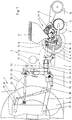
- Figures 1 to 3 each show a seeder as an embodiment of the new tillage machine.
- the tillage machine 1 shown in a longitudinal section in FIG. 1 is attached to a tractor 2.
- the seeder 2 has a frame 3 which rolls over the floor 5 via two lateral wheels 4.
- a number of single-grain sowing units 6 are each pivotably mounted in the vertical direction via a parallelogram link arrangement with upper links 7 and lower links 8.
- Each precision seed drill 6 has a rotating coulter 9 and a closing wheel 10 for the seed furrow provided by the coulter 9 as tillage tools.
- the depth of engagement of the coulter 9 in the ground 5 is determined by a support wheel 11 which rolls on the ground 5 when the desired depth of engagement is reached.
- the locking wheel 10 is pivotally supported by an arm 12 with respect to the other components of the precision seed drill 6 and is biased by the arm 12 in the direction of the ground 5.
- a spiral spring not shown here, is provided for this purpose.
- the single-grain sowing unit 6 also has a storage container 13 for the sawn and a separating device 14, from which individual seeds of the sawn are deposited in the seed furrow opened by the coulter 9.
- the separating device 14 has a gear connection to the impeller 4 of the frame 3 and is driven by the impeller 4. However, a separate motor drive for the separating device 14 can also be provided.
- the coulter 9 has a more or less tendency to escape from the ground 5.
- a hydraulic cylinder 15 acts on the parallelogram link arrangement between the frame 3 and the sowing unit 6.
- the first point of application 16 of the hydraulic cylinder 15 on the parallelogram linkage arrangement is located on the upper links 7.
- the second point of application 17 is located on an extension arm 18, which is rigidly connected to the sowing unit 6 and can be pivoted about the lower link 8 about a common axis of rotation 19 .
- the hydraulic cylinder 15 is connected via a branch line 20 to a gas-filled pressure accumulator 21. With a comparatively large gas volume in the pressure accumulator 21 in relation to the volume of hydraulic fluid displaced by the hydraulic cylinder, the hydraulic cylinder 15 acts on the precision seed drill 6 with an almost constant, ie path-independent, restoring force on the ground 5.
- This restoring force also acts on the frame 3, which tends to be raised by the restoring force.
- the frame 3 is attached to the tractor 2 via a four-axis handlebar arrangement.
- the four axes of rotation 22 to 25 of the link arrangement are arranged at the ends of lower links 26 of the tractor 2 that can be raised and on the ends of a pivotable upper link 27 arranged above them.
- the lower links 26 of the tractor 2 can be raised hydraulically by means of lifting rods 28 and lifting arms 29 and are reduced by their own weight or by means of attached weights.
- the length of the upper link 27 can be varied in order to adjust the inclination of the frame 3 relative to the floor 5.
- two hydraulic cylinders 30 assigned to the lower links 26 are provided.
- the hydraulic cylinders 30 engage on the one hand on the frame 3 and on a lever arm 31 a two-armed power transmission lever 31, 32 on the other hand.
- the second lever arm 32 of the power transmission lever 31, 32 engages the respective lower link 26 from below.
- the lever axis of the power transmission lever 31, 32 coincides with the axis of rotation 23. In this way, the hydraulic cylinder, when acted upon, causes a restoring force which presses the frame 3 downward relative to the tractor 2.
- the hydraulic cylinder 30 causes part of the weight on the rear wheels 33 of the tractor 2 to be transferred to the frame 3.
- the hydraulic cylinder 30 is acted upon by a line 34 from the pressure accumulator 21.
- the working pressure in the pressure accumulator 21 is indicated by a manometer 35.
- the working pressure in the pressure accumulator 21 is provided by the hydraulic system 37 of the tractor 2 via a pressure line 36.
- the pressure line 36 is an extension of the line 34.
- the pressure accumulator 21 does not have to be continuously supplied with pressure, but it is sufficient to fill it up once.
- the pressure system comprising the hydraulic cylinders 15 and 30, the branch lines 20, the line 34, the pressure gauge 35 and the pressure accumulator 21 can then be locked with a check valve 38.
- the pressure system is thus independent of leaks in the hydraulic system 37.
- the gas volume of the pressure accumulator 21 is advantageously many times larger than the volumes of hydraulic fluid that can be displaced by the individual hydraulic cylinders 15, 30. The restoring forces are therefore almost constant over the spring deflection of the hydraulic cylinders.
- the combination of the hydraulic cylinders 15, 30 with the gas-filled pressure accumulator 21 further advantageously leads to damping of vibrations between the frame 3 and the tractor 2 on the one hand and the frame 3 and the precision sowing units 6 on the other hand.
- the seed drill 2 shown in FIG. 2 differs from that shown in FIG. 1 by additional fertilizer lances 39 rigidly mounted on the frame 3.
- the fertilizer lances 39 are each assigned to a sowing unit 6 and are used to introduce fertilizers into the respective sowing track.
- the fertilizer lances 39 are soil cultivation tools which penetrate the soil 5 and tend to be pushed upwards out of the soil 5.
- the fertilizer lances 39 also transmit an upward force to the frame 3. This force is counteracted by the hydraulic cylinders 30 in the four-axis link arrangement 26, 27 between the tractor 1 and the frame 3 in order to prevent the frame 3 from escaping upwards.
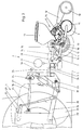
- the seed drill according to FIG. 3 differs from that according to FIG. 1 by the arrangement of the hydraulic cylinders 30 in the four-axis link arrangement 26, 27. While the hydraulic cylinders 30 according to FIG. 1 are designed as pressure cylinders with a circular area acted upon by the hydraulic fluid, the latter are Hydraulic cylinders 30 according to FIG. 3 around pull cylinders with annular surfaces acted upon by the hydraulic fluid. In this case, the hydraulic cylinders 30 according to FIG. 3 act on the lever arms 32 facing the lower links of the force transmission levers 32 which are designed here with only one arm. The power transmission levers 32 are also here from below to the lower links 26 pressed and lead to an action of the frame 3 on the floor 5.
- the hydraulic cylinders 15 in the parallelogram link arrangement 7, 8 are also designed as pull cylinders with an annular surface acted upon by the hydraulic fluid. In addition, they differ in the location of their points of attack. According to FIG. 3, the hydraulic cylinders 15 act exclusively on the upper links 7 and the lower links 8 of the parallelogram linkages 7, 8. The resultant action on the sowing units 6 is, however, also directed downwards onto the floor 5 here.
Landscapes
- Life Sciences & Earth Sciences (AREA)
- Engineering & Computer Science (AREA)
- Mechanical Engineering (AREA)
- Soil Sciences (AREA)
- Environmental Sciences (AREA)
- Soil Working Implements (AREA)
- Zoology (AREA)
- Sowing (AREA)
- Agricultural Machines (AREA)
Applications Claiming Priority (4)
| Application Number | Priority Date | Filing Date | Title |
|---|---|---|---|
| DE4321579 | 1993-06-29 | ||
| DE4321579 | 1993-06-29 | ||
| DE4323154 | 1993-07-10 | ||
| DE4323154A DE4323154C2 (de) | 1993-06-29 | 1993-07-10 | Bodenbearbeitungsmaschine |
Publications (3)
| Publication Number | Publication Date |
|---|---|
| EP0632953A2 true EP0632953A2 (fr) | 1995-01-11 |
| EP0632953A3 EP0632953A3 (fr) | 1996-04-03 |
| EP0632953B1 EP0632953B1 (fr) | 1999-12-29 |
Family
ID=25927224
Family Applications (1)
| Application Number | Title | Priority Date | Filing Date |
|---|---|---|---|
| EP94109538A Expired - Lifetime EP0632953B1 (fr) | 1993-06-29 | 1994-06-21 | Machine pour le travail du sol |
Country Status (5)
| Country | Link |
|---|---|
| EP (1) | EP0632953B1 (fr) |
| AT (1) | ATE188083T1 (fr) |
| DE (1) | DE4323154C2 (fr) |
| DK (1) | DK0632953T3 (fr) |
| ES (1) | ES2141783T3 (fr) |
Cited By (8)
| Publication number | Priority date | Publication date | Assignee | Title |
|---|---|---|---|---|
| WO1996029852A1 (fr) * | 1995-03-29 | 1996-10-03 | Kverneland Klepp A/S | Outil agricole remorquable |
| WO1998014045A1 (fr) * | 1996-10-02 | 1998-04-09 | Kverneland Klepp As | Engin agricole pouvant etre remorque |
| EP1438886A1 (fr) * | 2003-01-16 | 2004-07-21 | Deere & Company | Dispositif d'accouplement |
| EP2363013A1 (fr) * | 2010-03-02 | 2011-09-07 | Lemken GmbH & Co. KG | Combiné de semis doté d'un dispositif pour maintenir une valeur limite de glissement |
| FR2961656A1 (fr) * | 2010-06-28 | 2011-12-30 | Kuhn | Semoir de precision avec au moins un groupe d'outils de travail en bandes integre |
| EP2769609A1 (fr) * | 2013-02-22 | 2014-08-27 | Amazonen-Werke H. Dreyer GmbH & Co. KG | Machine agricole tractée pouvant être attachée à un tracteur |
| EP2769608A1 (fr) * | 2013-02-22 | 2014-08-27 | Amazonen-Werke H. Dreyer GmbH & Co. KG | Machine agricole tractée pouvant être attachée à un tracteur |
| EP3020261A1 (fr) * | 2014-11-12 | 2016-05-18 | Deere & Company | Combinaison d'un vehicule de traction agricole et d'un semoir direct |
Families Citing this family (1)
| Publication number | Priority date | Publication date | Assignee | Title |
|---|---|---|---|---|
| DE10238685A1 (de) * | 2002-08-19 | 2004-03-11 | Josef Kerner | Säschiene mit mehreren gestaffelt angeordneten Säscharen mit nachgeordneten Druckrollen |
Citations (9)
| Publication number | Priority date | Publication date | Assignee | Title |
|---|---|---|---|---|
| DE803811C (de) * | 1949-06-23 | 1951-04-09 | Heinrich Lanz Akt Ges | Zugmaschine mit motorischem Kraftheber |
| DE1149615B (de) * | 1956-09-29 | 1963-05-30 | Bosch Gmbh Robert | Hydraulische Kraftuebertragungsanlage mit Druckspeicher |
| DE1920898A1 (de) * | 1968-09-13 | 1970-11-05 | Rabewerk Clausing Heinrich | Anordnung zur zusaetzlichen intermittierenden Belastung der Hinterraeder eines Schleppers mit angehaengtem Aufsattelpflug |
| DE2060871A1 (de) * | 1969-12-17 | 1971-07-01 | Junnila Lauri Johannes | Hebe- und Gewichtsverlagerungsmechanismus fuer Arbeitsgeraete zum Anschluss an einen Schlepper |
| FR2505130A1 (fr) * | 1981-05-06 | 1982-11-12 | Amazonen Werke Dreyer H | Semoir mecanique avec dispositif d'attelage |
| FR2521817A1 (fr) * | 1982-02-19 | 1983-08-26 | Amazonen Werke Dreyer H | Combinaison d'appareils agricoles tels cultivateur, rouleau et semoir mecanique |
| DE3327568A1 (de) * | 1983-07-30 | 1985-02-07 | Ernst 7326 Heiningen Weichel | Mehrfach-geraetekombination fuer traktoren zur bodenlockerung, saatbettherrichtung und bestellung |
| DE3607257A1 (de) * | 1986-03-05 | 1987-09-10 | Fritzmeier Georg Gmbh & Co | Vorrichtung zur zusaetzlichen belastung eines an einen landwirtschaftlichen schlepper in schwimmstellung angebauten arbeitsgeraets |
| US4858698A (en) * | 1988-06-10 | 1989-08-22 | Yetter Manufacturing Company | Weight transfer linkage arrangement |
Family Cites Families (1)
| Publication number | Priority date | Publication date | Assignee | Title |
|---|---|---|---|---|
| DE3607267A1 (de) * | 1986-03-05 | 1987-09-10 | Fritzmeier Georg Gmbh & Co | Durchsaatvorrichtung |
-
1993
- 1993-07-10 DE DE4323154A patent/DE4323154C2/de not_active Expired - Lifetime
-
1994
- 1994-06-21 EP EP94109538A patent/EP0632953B1/fr not_active Expired - Lifetime
- 1994-06-21 AT AT94109538T patent/ATE188083T1/de not_active IP Right Cessation
- 1994-06-21 DK DK94109538T patent/DK0632953T3/da active
- 1994-06-21 ES ES94109538T patent/ES2141783T3/es not_active Expired - Lifetime
Patent Citations (9)
| Publication number | Priority date | Publication date | Assignee | Title |
|---|---|---|---|---|
| DE803811C (de) * | 1949-06-23 | 1951-04-09 | Heinrich Lanz Akt Ges | Zugmaschine mit motorischem Kraftheber |
| DE1149615B (de) * | 1956-09-29 | 1963-05-30 | Bosch Gmbh Robert | Hydraulische Kraftuebertragungsanlage mit Druckspeicher |
| DE1920898A1 (de) * | 1968-09-13 | 1970-11-05 | Rabewerk Clausing Heinrich | Anordnung zur zusaetzlichen intermittierenden Belastung der Hinterraeder eines Schleppers mit angehaengtem Aufsattelpflug |
| DE2060871A1 (de) * | 1969-12-17 | 1971-07-01 | Junnila Lauri Johannes | Hebe- und Gewichtsverlagerungsmechanismus fuer Arbeitsgeraete zum Anschluss an einen Schlepper |
| FR2505130A1 (fr) * | 1981-05-06 | 1982-11-12 | Amazonen Werke Dreyer H | Semoir mecanique avec dispositif d'attelage |
| FR2521817A1 (fr) * | 1982-02-19 | 1983-08-26 | Amazonen Werke Dreyer H | Combinaison d'appareils agricoles tels cultivateur, rouleau et semoir mecanique |
| DE3327568A1 (de) * | 1983-07-30 | 1985-02-07 | Ernst 7326 Heiningen Weichel | Mehrfach-geraetekombination fuer traktoren zur bodenlockerung, saatbettherrichtung und bestellung |
| DE3607257A1 (de) * | 1986-03-05 | 1987-09-10 | Fritzmeier Georg Gmbh & Co | Vorrichtung zur zusaetzlichen belastung eines an einen landwirtschaftlichen schlepper in schwimmstellung angebauten arbeitsgeraets |
| US4858698A (en) * | 1988-06-10 | 1989-08-22 | Yetter Manufacturing Company | Weight transfer linkage arrangement |
Cited By (10)
| Publication number | Priority date | Publication date | Assignee | Title |
|---|---|---|---|---|
| WO1996029852A1 (fr) * | 1995-03-29 | 1996-10-03 | Kverneland Klepp A/S | Outil agricole remorquable |
| US5868207A (en) * | 1995-03-29 | 1999-02-09 | Kverneland Klepp As | Agricultural implement having a set of ground working tools |
| WO1998014045A1 (fr) * | 1996-10-02 | 1998-04-09 | Kverneland Klepp As | Engin agricole pouvant etre remorque |
| EP1438886A1 (fr) * | 2003-01-16 | 2004-07-21 | Deere & Company | Dispositif d'accouplement |
| EP2363013A1 (fr) * | 2010-03-02 | 2011-09-07 | Lemken GmbH & Co. KG | Combiné de semis doté d'un dispositif pour maintenir une valeur limite de glissement |
| FR2961656A1 (fr) * | 2010-06-28 | 2011-12-30 | Kuhn | Semoir de precision avec au moins un groupe d'outils de travail en bandes integre |
| EP2769609A1 (fr) * | 2013-02-22 | 2014-08-27 | Amazonen-Werke H. Dreyer GmbH & Co. KG | Machine agricole tractée pouvant être attachée à un tracteur |
| EP2769608A1 (fr) * | 2013-02-22 | 2014-08-27 | Amazonen-Werke H. Dreyer GmbH & Co. KG | Machine agricole tractée pouvant être attachée à un tracteur |
| EP3020261A1 (fr) * | 2014-11-12 | 2016-05-18 | Deere & Company | Combinaison d'un vehicule de traction agricole et d'un semoir direct |
| US9861023B2 (en) | 2014-11-12 | 2018-01-09 | Deere & Company | Combination of an agricultural towing vehicle and a seeder |
Also Published As
| Publication number | Publication date |
|---|---|
| ATE188083T1 (de) | 2000-01-15 |
| DE4323154C2 (de) | 1995-07-06 |
| DE4323154A1 (de) | 1995-01-12 |
| DK0632953T3 (da) | 2000-04-17 |
| EP0632953A3 (fr) | 1996-04-03 |
| EP0632953B1 (fr) | 1999-12-29 |
| ES2141783T3 (es) | 2000-04-01 |
Similar Documents
| Publication | Publication Date | Title |
|---|---|---|
| DE2813295A1 (de) | Saatgut- und/oder duengerstreumaschine | |
| DE2428917C3 (de) | Bodenbearbeitungsgerät | |
| DE102010006169B4 (de) | Doppelscheibenschar mit Tiefenführungsrolle | |
| EP3245855A1 (fr) | Cultivateur, dents plates associées et système de dents plates | |
| DE4323154C2 (de) | Bodenbearbeitungsmaschine | |
| DE2248186B2 (fr) | ||
| EP3242543B1 (fr) | Engin agricole à châssis de roulement supplémentaire | |
| DE19534740C2 (de) | Drillmaschine zum Ausbringen von Saatgut in vorbereitetem und nicht vorbereitetem Boden | |
| DE29605356U1 (de) | Sägerät, insbesondere für Mulchsaat | |
| EP3782443B1 (fr) | Machine de traitement du sol agricole destinée au traitement des cultures sur rang | |
| EP1929852B1 (fr) | Dispositif destiné à déraciner ou à récolter de plantes à racines | |
| EP3020261B1 (fr) | Combinaison d'un vehicule de traction agricole et d'un semoir direct | |
| DE7520589U (de) | Alandwirtschaftliches bodenbearbeitungsgeraet, insbesondere kruemler | |
| DE3607257A1 (de) | Vorrichtung zur zusaetzlichen belastung eines an einen landwirtschaftlichen schlepper in schwimmstellung angebauten arbeitsgeraets | |
| EP0982571A2 (fr) | Dispositif de détection du poids d'une machine agricole | |
| EP0640272B1 (fr) | Machine combinée pour le travail du sol | |
| DE102010046745A1 (de) | Aufsatteldrehpflug | |
| DE102015108279A1 (de) | Säschar mit Furchenöffner einer landwirtschaftlichen Maschine | |
| EP3698616B1 (fr) | Agencement de soc pourvu de rouleau de pression à régulation de la pression | |
| EP3909407A1 (fr) | Machine agricole tractée et procédé pour influencer une force d'appui d'une machine agricole tractée | |
| EP0556459A1 (fr) | Charrue réversible attelable ou accrochable | |
| DE9405681U1 (de) | Bodenbearbeitungsmaschine | |
| EP0359896A2 (fr) | Machine combinée | |
| DE102014223843A1 (de) | Kombination aus einem landwirtschaftlichen Zugfahrzeug und einer Direktsaat-Sämaschine | |
| DE102021134216A1 (de) | Landwirtschaftliche Arbeitsmaschine und Verfahren zur Gewichtsverlagerung an einer landwirtschaftlichen Arbeitsmaschine |
Legal Events
| Date | Code | Title | Description |
|---|---|---|---|
| PUAI | Public reference made under article 153(3) epc to a published international application that has entered the european phase |
Free format text: ORIGINAL CODE: 0009012 |
|
| AK | Designated contracting states |
Kind code of ref document: A2 Designated state(s): AT BE CH DK ES FR GB IT LI NL SE |
|
| PUAL | Search report despatched |
Free format text: ORIGINAL CODE: 0009013 |
|
| AK | Designated contracting states |
Kind code of ref document: A3 Designated state(s): AT BE CH DK ES FR GB IT LI NL SE |
|
| 17P | Request for examination filed |
Effective date: 19960626 |
|
| 17Q | First examination report despatched |
Effective date: 19980813 |
|
| GRAG | Despatch of communication of intention to grant |
Free format text: ORIGINAL CODE: EPIDOS AGRA |
|
| GRAG | Despatch of communication of intention to grant |
Free format text: ORIGINAL CODE: EPIDOS AGRA |
|
| GRAH | Despatch of communication of intention to grant a patent |
Free format text: ORIGINAL CODE: EPIDOS IGRA |
|
| RAP1 | Party data changed (applicant data changed or rights of an application transferred) |
Owner name: FRANZ KLEINE AGRARTECHNIK GMBH |
|
| ITF | It: translation for a ep patent filed | ||
| GRAH | Despatch of communication of intention to grant a patent |
Free format text: ORIGINAL CODE: EPIDOS IGRA |
|
| GRAA | (expected) grant |
Free format text: ORIGINAL CODE: 0009210 |
|
| AK | Designated contracting states |
Kind code of ref document: B1 Designated state(s): AT BE CH DK ES FR GB IT LI NL SE |
|
| REF | Corresponds to: |
Ref document number: 188083 Country of ref document: AT Date of ref document: 20000115 Kind code of ref document: T |
|
| REG | Reference to a national code |
Ref country code: CH Ref legal event code: EP |
|
| REG | Reference to a national code |
Ref country code: CH Ref legal event code: NV Representative=s name: RIEDERER HASLER & PARTNER PATENTANWAELTE AG |
|
| ET | Fr: translation filed | ||
| REG | Reference to a national code |
Ref country code: ES Ref legal event code: FG2A Ref document number: 2141783 Country of ref document: ES Kind code of ref document: T3 |
|
| REG | Reference to a national code |
Ref country code: DK Ref legal event code: T3 |
|
| GBT | Gb: translation of ep patent filed (gb section 77(6)(a)/1977) |
Effective date: 20000328 |
|
| PLBE | No opposition filed within time limit |
Free format text: ORIGINAL CODE: 0009261 |
|
| STAA | Information on the status of an ep patent application or granted ep patent |
Free format text: STATUS: NO OPPOSITION FILED WITHIN TIME LIMIT |
|
| 26N | No opposition filed | ||
| REG | Reference to a national code |
Ref country code: GB Ref legal event code: IF02 |
|
| PGFP | Annual fee paid to national office [announced via postgrant information from national office to epo] |
Ref country code: GB Payment date: 20050613 Year of fee payment: 12 |
|
| PGFP | Annual fee paid to national office [announced via postgrant information from national office to epo] |
Ref country code: NL Payment date: 20050620 Year of fee payment: 12 |
|
| PG25 | Lapsed in a contracting state [announced via postgrant information from national office to epo] |
Ref country code: IT Free format text: LAPSE BECAUSE OF NON-PAYMENT OF DUE FEES;WARNING: LAPSES OF ITALIAN PATENTS WITH EFFECTIVE DATE BEFORE 2007 MAY HAVE OCCURRED AT ANY TIME BEFORE 2007. THE CORRECT EFFECTIVE DATE MAY BE DIFFERENT FROM THE ONE RECORDED. Effective date: 20050621 |
|
| PGFP | Annual fee paid to national office [announced via postgrant information from national office to epo] |
Ref country code: BE Payment date: 20050623 Year of fee payment: 12 |
|
| PGFP | Annual fee paid to national office [announced via postgrant information from national office to epo] |
Ref country code: CH Payment date: 20050624 Year of fee payment: 12 |
|
| PGFP | Annual fee paid to national office [announced via postgrant information from national office to epo] |
Ref country code: DK Payment date: 20050627 Year of fee payment: 12 |
|
| PGFP | Annual fee paid to national office [announced via postgrant information from national office to epo] |
Ref country code: ES Payment date: 20050628 Year of fee payment: 12 Ref country code: AT Payment date: 20050628 Year of fee payment: 12 |
|
| PGFP | Annual fee paid to national office [announced via postgrant information from national office to epo] |
Ref country code: SE Payment date: 20050629 Year of fee payment: 12 |
|
| PG25 | Lapsed in a contracting state [announced via postgrant information from national office to epo] |
Ref country code: GB Free format text: LAPSE BECAUSE OF NON-PAYMENT OF DUE FEES Effective date: 20060621 Ref country code: AT Free format text: LAPSE BECAUSE OF NON-PAYMENT OF DUE FEES Effective date: 20060621 |
|
| PG25 | Lapsed in a contracting state [announced via postgrant information from national office to epo] |
Ref country code: SE Free format text: LAPSE BECAUSE OF NON-PAYMENT OF DUE FEES Effective date: 20060622 Ref country code: ES Free format text: LAPSE BECAUSE OF NON-PAYMENT OF DUE FEES Effective date: 20060622 |
|
| PG25 | Lapsed in a contracting state [announced via postgrant information from national office to epo] |
Ref country code: LI Free format text: LAPSE BECAUSE OF NON-PAYMENT OF DUE FEES Effective date: 20060630 Ref country code: DK Free format text: LAPSE BECAUSE OF NON-PAYMENT OF DUE FEES Effective date: 20060630 Ref country code: CH Free format text: LAPSE BECAUSE OF NON-PAYMENT OF DUE FEES Effective date: 20060630 Ref country code: BE Free format text: LAPSE BECAUSE OF NON-PAYMENT OF DUE FEES Effective date: 20060630 |
|
| PG25 | Lapsed in a contracting state [announced via postgrant information from national office to epo] |
Ref country code: NL Free format text: LAPSE BECAUSE OF NON-PAYMENT OF DUE FEES Effective date: 20070101 |
|
| REG | Reference to a national code |
Ref country code: DK Ref legal event code: EBP |
|
| REG | Reference to a national code |
Ref country code: CH Ref legal event code: PL |
|
| EUG | Se: european patent has lapsed | ||
| GBPC | Gb: european patent ceased through non-payment of renewal fee |
Effective date: 20060621 |
|
| NLV4 | Nl: lapsed or anulled due to non-payment of the annual fee |
Effective date: 20070101 |
|
| REG | Reference to a national code |
Ref country code: ES Ref legal event code: FD2A Effective date: 20060622 |
|
| BERE | Be: lapsed |
Owner name: FRANZ *KLEINE AGRARTECHNIK G.M.B.H. Effective date: 20060630 |
|
| PGFP | Annual fee paid to national office [announced via postgrant information from national office to epo] |
Ref country code: FR Payment date: 20130703 Year of fee payment: 20 |