EP0632476B1 - Relais perfectionné - Google Patents
Relais perfectionné Download PDFInfo
- Publication number
- EP0632476B1 EP0632476B1 EP94401276A EP94401276A EP0632476B1 EP 0632476 B1 EP0632476 B1 EP 0632476B1 EP 94401276 A EP94401276 A EP 94401276A EP 94401276 A EP94401276 A EP 94401276A EP 0632476 B1 EP0632476 B1 EP 0632476B1
- Authority
- EP
- European Patent Office
- Prior art keywords
- piece
- base
- electromagnet
- support
- assembly
- Prior art date
- Legal status (The legal status is an assumption and is not a legal conclusion. Google has not performed a legal analysis and makes no representation as to the accuracy of the status listed.)
- Expired - Lifetime
Links
- 239000002184 metal Substances 0.000 claims abstract description 4
- 230000015572 biosynthetic process Effects 0.000 claims description 15
- 238000005755 formation reaction Methods 0.000 claims description 15
- 230000007246 mechanism Effects 0.000 claims description 11
- 238000004804 winding Methods 0.000 claims description 2
- 230000014759 maintenance of location Effects 0.000 claims 2
- 230000000903 blocking effect Effects 0.000 claims 1
- 230000037431 insertion Effects 0.000 claims 1
- 238000003780 insertion Methods 0.000 claims 1
- 239000000470 constituent Substances 0.000 description 2
- 238000010276 construction Methods 0.000 description 2
- 230000000694 effects Effects 0.000 description 2
- 230000004907 flux Effects 0.000 description 2
- 206010003830 Automatism Diseases 0.000 description 1
- 230000004075 alteration Effects 0.000 description 1
- 230000007423 decrease Effects 0.000 description 1
- 238000010616 electrical installation Methods 0.000 description 1
- 238000004519 manufacturing process Methods 0.000 description 1
- 239000000463 material Substances 0.000 description 1
- 230000035755 proliferation Effects 0.000 description 1
- 229920002994 synthetic fiber Polymers 0.000 description 1
- 238000003466 welding Methods 0.000 description 1
Images


Classifications
-
- H—ELECTRICITY
- H01—ELECTRIC ELEMENTS
- H01H—ELECTRIC SWITCHES; RELAYS; SELECTORS; EMERGENCY PROTECTIVE DEVICES
- H01H71/00—Details of the protective switches or relays covered by groups H01H73/00 - H01H83/00
- H01H71/10—Operating or release mechanisms
- H01H71/12—Automatic release mechanisms with or without manual release
- H01H71/24—Electromagnetic mechanisms
- H01H71/32—Electromagnetic mechanisms having permanently magnetised part
- H01H71/321—Electromagnetic mechanisms having permanently magnetised part characterised by the magnetic circuit or active magnetic elements
- H01H71/323—Electromagnetic mechanisms having permanently magnetised part characterised by the magnetic circuit or active magnetic elements with rotatable armature
-
- H—ELECTRICITY
- H01—ELECTRIC ELEMENTS
- H01H—ELECTRIC SWITCHES; RELAYS; SELECTORS; EMERGENCY PROTECTIVE DEVICES
- H01H71/00—Details of the protective switches or relays covered by groups H01H73/00 - H01H83/00
- H01H71/02—Housings; Casings; Bases; Mountings
- H01H71/0207—Mounting or assembling the different parts of the circuit breaker
- H01H2071/0242—Assembling parts of a circuit breaker by using snap mounting techniques
-
- H—ELECTRICITY
- H01—ELECTRIC ELEMENTS
- H01H—ELECTRIC SWITCHES; RELAYS; SELECTORS; EMERGENCY PROTECTIVE DEVICES
- H01H71/00—Details of the protective switches or relays covered by groups H01H73/00 - H01H83/00
- H01H71/10—Operating or release mechanisms
- H01H71/12—Automatic release mechanisms with or without manual release
- H01H71/24—Electromagnetic mechanisms
- H01H71/32—Electromagnetic mechanisms having permanently magnetised part
- H01H71/325—Housings, assembly or disposition of different elements in the housing
Definitions
- Said devices consist in principle of an electromagnet and a metal part capable of being moved under the control of this last between two or more positions for the performance of a function any definite concrete which can be, for example, closure and opening a duct, etc.
- EP-A-0 369 111 describes a relay constituted by a containing carcass provided with a closing base, however a mechanism is provided inside formed of an electromagnet and a moving part which is arranged in assembly tilting on a corresponding support, the central part of the moving part leaning on the support.
- the central part of a flat "U” shaped spring supports the moving part at the end thereof which is distant from the electromagnet, while the ends of the flat spring are in turn supported by a bar provided on said support.
- a coil spring arranged in the vertical direction is connected to the tilting piece at the end of which is supported by the flat spring, in order to apply a force to this part intended to interrupt the contact between it and the electromagnet.
- the present invention provides a relay constituted by a carcass container provided with a closing base and means used for fixing to the place application, however that there is provided inside a mechanism formed of a electromagnet and a moving part which is arranged in tilting mounting on a corresponding support, characterized in that the moving part is arranged on the support by fitting into the latter by lateral pins which play the role of axes of rotation, said part being drawn to the rear, where it forms a end folded upwards in a "U" shape, by means of a built-in spring between the free edge of the mentioned extreme configuration and the support mounting.
- this recommended relay certainly has very benefits that give its realization a life of its own and a preferable compared to conventional relays.
- Figure 1 shows an exploded perspective view of the assembly constituting the relay that we recommend.
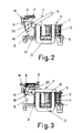
- FIG. 2 is a side view in section of the assembled assembly of the functional mechanism of said relay object of the invention, in the disarmed position.
- Figure 3 is a view similar to that of the previous figure, in the position of the armed mechanism.
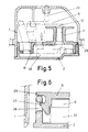
- FIG. 4 is an exploded perspective of the structural assembly of the relay, without the functional mechanism, compliant to a particular example of practical realization.
- Figure 5 is a sectional view of the mounted assembly of said previous embodiment example.
- Figure 6 is an enlarged drawing corresponding to the safety catch of the mounting of the basic part which carries the coil body of the electromagnet, in accordance with the aforementioned previous embodiment example.
- the object of the invention consists of a relay of the type of those that we use as a functional device for realization of various control and command functions in electrical installations, said relay being essentially constituted by a functional mechanism which is housed inside a carcass (1) which, according to an embodiment, is closed by means of a base (2) which is fixed by fitting lateral pins (3) in corresponding holes (4) of the carcass (1) while the latter is in turn provided with formations (5) for the fixing, by screwing or any other similar means, at the place of application.
- the functional mechanism for its part, consists of a classic way, an electromagnet (6) and a part mobile (7) can be controlled by it but, so particular, said movable part (7) being arranged in a tilting mounting, mounted on a respective support (8) by relationship to which it is also attracted in terms of its rear part by a spring (9) which tends to hold it away from the electromagnet (6) as can be seen on Figure 2.
- the mechanism further includes a base piece (10) which, like the carcass (1), the base (2) and the support (8), is made of an insulating synthetic material, this base part (10) forming a flat body in the form of a plate, on which rises a solidarity formation (11) which constitutes the reel body for winding the reel corresponding (12) of the electromagnet (6).
- the core of the mentioned electromagnet (6) consists in turn by a metal part (13) in the shape of a "U”, which fits axially by one of its branches to through the coil body (11), forming the core proper, while the other branch goes through a respective opening (14) of the flat body of the part (10), by fitting on the other side into a defined housing (21) by the support (8) of the tilting part (7), so that thus, by means of said part (13) which constitutes the core, both fixing the support (8) mentioned and the formation of the functional core of the electromagnet (6) mentioned; the part (13) mentioned disposing supported by a permanent magnet (22) which is housed in the base (2).
- the part tilting (7) mentioned is constituted by a plate metallic (15) in the form of a pallet and a supporting part (16) in the shape of a "U", the two being joined by fixing secured by matting, spot welding or any another conventional form, said load-bearing part (16) defining a small formation (17) in its upper part, for the attachment of the spring (9) in the tension thereof by relation to another reciprocal attachment formation (18) defined in the support (8); while, laterally, this part (16) in the form of small pins (19) which serve as axes tilting for mounting on the support (8), in this direction that the latter fit into housing slots corresponding (20).
Landscapes
- Physics & Mathematics (AREA)
- Electromagnetism (AREA)
- Electromagnets (AREA)
- Control Of Motors That Do Not Use Commutators (AREA)
- Glass Compositions (AREA)
- Fluid-Damping Devices (AREA)
- Non-Silver Salt Photosensitive Materials And Non-Silver Salt Photography (AREA)
- Percussion Or Vibration Massage (AREA)
- Vending Machines For Individual Products (AREA)
Applications Claiming Priority (2)
| Application Number | Priority Date | Filing Date | Title |
|---|---|---|---|
| ES9301805 | 1993-06-30 | ||
| ES9301805U ES1025149Y (es) | 1993-06-30 | 1993-06-30 | Rele perfeccionado. |
Publications (2)
| Publication Number | Publication Date |
|---|---|
| EP0632476A1 EP0632476A1 (fr) | 1995-01-04 |
| EP0632476B1 true EP0632476B1 (fr) | 1998-01-28 |
Family
ID=8282861
Family Applications (1)
| Application Number | Title | Priority Date | Filing Date |
|---|---|---|---|
| EP94401276A Expired - Lifetime EP0632476B1 (fr) | 1993-06-30 | 1994-06-08 | Relais perfectionné |
Country Status (5)
| Country | Link |
|---|---|
| EP (1) | EP0632476B1 (da) |
| AT (1) | ATE162905T1 (da) |
| DE (1) | DE69408217T2 (da) |
| DK (1) | DK0632476T3 (da) |
| ES (1) | ES1025149Y (da) |
Family Cites Families (3)
| Publication number | Priority date | Publication date | Assignee | Title |
|---|---|---|---|---|
| DE3643510A1 (de) * | 1986-12-19 | 1988-06-30 | Felten & Guilleaume Energie | Magnetsystem fuer schnellabschaltung |
| DE3838444A1 (de) * | 1988-11-12 | 1990-05-17 | Felten & Guilleaume Energie | Magnetsystem fuer schnellabschaltung |
| DE4111092A1 (de) * | 1991-04-07 | 1992-10-08 | Schiele Gmbh & Co Kg | Fehlerstromrelais |
-
1993
- 1993-06-30 ES ES9301805U patent/ES1025149Y/es not_active Expired - Fee Related
-
1994
- 1994-06-08 DE DE69408217T patent/DE69408217T2/de not_active Expired - Lifetime
- 1994-06-08 EP EP94401276A patent/EP0632476B1/fr not_active Expired - Lifetime
- 1994-06-08 AT AT94401276T patent/ATE162905T1/de not_active IP Right Cessation
- 1994-06-08 DK DK94401276T patent/DK0632476T3/da active
Also Published As
| Publication number | Publication date |
|---|---|
| ATE162905T1 (de) | 1998-02-15 |
| ES1025149U (es) | 1993-11-16 |
| ES1025149Y (es) | 1994-06-01 |
| DE69408217D1 (de) | 1998-03-05 |
| EP0632476A1 (fr) | 1995-01-04 |
| DE69408217T2 (de) | 1998-09-17 |
| DK0632476T3 (da) | 1998-09-21 |
Similar Documents
| Publication | Publication Date | Title |
|---|---|---|
| EP0469950B1 (fr) | Montre-bracelet avec boîtier à couvercle interchangeable | |
| CA1097385A (fr) | Plinthe automatique | |
| CH558645A (en) | Rocking garden seat - mechanism incorporates slider actuated by electrical contact breaker | |
| EP0343494A1 (fr) | Dispositif d'alarme pour pièce d'horlogerie | |
| FR2541754A1 (fr) | Lampe de lecture portative | |
| CH690206A5 (fr) | Montre de poche et de table avec dispositif de suspension et de support. | |
| EP0632476B1 (fr) | Relais perfectionné | |
| CA1203825A (fr) | Dispositif amovible de verrouillage d'un contacteur dans sa position de travail | |
| EP0837957B1 (fr) | Dispositif pour la selection de crochets dans une mecanique d'armure de metier a tisser | |
| EP0643410B1 (fr) | Relais | |
| FR2510302A1 (fr) | Relais electromagnetique | |
| EP0866483B1 (fr) | Coupe-batterie bi-stable à verrouillage mécanique | |
| FR2820079A1 (fr) | Mecanisme de fermeture pour classeur | |
| EP0159075A1 (fr) | Cassette pour bande vidéo | |
| FR2520156A1 (fr) | Interrupteur electrique actionne par flotteur | |
| EP1089144B1 (fr) | Bride de contact de poussoir multifonction | |
| EP0013228B1 (fr) | Entrebâilleur de fenêtre | |
| EP0791865B1 (fr) | Montre de poche et de table avec dispositif de suspension et de support | |
| FR2549264A1 (fr) | Dispositif d'affichage ou indicateur | |
| EP1558973A1 (fr) | Dispositif de commande pour poussoir, notamment de piece d'horlogerie, et instrument electronique portable comprenant un tel dispositif | |
| FR2744538A1 (fr) | Montre de poche et de table avec dispositif de suspension et de support | |
| FR2892558A1 (fr) | Systeme de contact pour un interrupteur a basse tension | |
| EP2442337B1 (fr) | Dispositif de contacteur clé | |
| FR2807089A1 (fr) | Serrure electromagnetique | |
| FR2705485A1 (fr) | Mouvement pour boîte à musique avec détente d'arrêt. |
Legal Events
| Date | Code | Title | Description |
|---|---|---|---|
| PUAI | Public reference made under article 153(3) epc to a published international application that has entered the european phase |
Free format text: ORIGINAL CODE: 0009012 |
|
| AK | Designated contracting states |
Kind code of ref document: A1 Designated state(s): AT BE CH DE DK FR GB GR IE IT LI LU MC NL PT SE |
|
| 17P | Request for examination filed |
Effective date: 19950524 |
|
| 17Q | First examination report despatched |
Effective date: 19960708 |
|
| RAP3 | Party data changed (applicant data changed or rights of an application transferred) |
Owner name: ELECTRICAL DISTRIBUTION AND CONTROL ESPANA, S.A. |
|
| RAP3 | Party data changed (applicant data changed or rights of an application transferred) |
Owner name: ELECTRICAL DISTRIBUTION & CONTROL ESPANA, S.A. |
|
| GRAG | Despatch of communication of intention to grant |
Free format text: ORIGINAL CODE: EPIDOS AGRA |
|
| GRAG | Despatch of communication of intention to grant |
Free format text: ORIGINAL CODE: EPIDOS AGRA |
|
| GRAG | Despatch of communication of intention to grant |
Free format text: ORIGINAL CODE: EPIDOS AGRA |
|
| GRAH | Despatch of communication of intention to grant a patent |
Free format text: ORIGINAL CODE: EPIDOS IGRA |
|
| GRAH | Despatch of communication of intention to grant a patent |
Free format text: ORIGINAL CODE: EPIDOS IGRA |
|
| GRAA | (expected) grant |
Free format text: ORIGINAL CODE: 0009210 |
|
| AK | Designated contracting states |
Kind code of ref document: B1 Designated state(s): AT BE CH DE DK FR GB GR IE IT LI LU MC NL PT SE |
|
| REF | Corresponds to: |
Ref document number: 162905 Country of ref document: AT Date of ref document: 19980215 Kind code of ref document: T |
|
| RIN1 | Information on inventor provided before grant (corrected) |
Inventor name: RIQUELME LOPEZ, PEDRO J. Inventor name: BONILLA HERNANDEZ, JORGE J. Inventor name: PEREZ LOPEZ, PEDRO |
|
| REG | Reference to a national code |
Ref country code: CH Ref legal event code: EP |
|
| GBT | Gb: translation of ep patent filed (gb section 77(6)(a)/1977) |
Effective date: 19980203 |
|
| REF | Corresponds to: |
Ref document number: 69408217 Country of ref document: DE Date of ref document: 19980305 |
|
| ITF | It: translation for a ep patent filed | ||
| REG | Reference to a national code |
Ref country code: CH Ref legal event code: NV Representative=s name: MICHELI & CIE INGENIEURS-CONSEILS |
|
| REG | Reference to a national code |
Ref country code: IE Ref legal event code: FG4D Free format text: 78663 |
|
| REG | Reference to a national code |
Ref country code: PT Ref legal event code: SC4A Free format text: AVAILABILITY OF NATIONAL TRANSLATION Effective date: 19980327 |
|
| REG | Reference to a national code |
Ref country code: DK Ref legal event code: T3 |
|
| PLBE | No opposition filed within time limit |
Free format text: ORIGINAL CODE: 0009261 |
|
| STAA | Information on the status of an ep patent application or granted ep patent |
Free format text: STATUS: NO OPPOSITION FILED WITHIN TIME LIMIT |
|
| 26N | No opposition filed | ||
| REG | Reference to a national code |
Ref country code: GB Ref legal event code: IF02 |
|
| PGFP | Annual fee paid to national office [announced via postgrant information from national office to epo] |
Ref country code: DK Payment date: 20080620 Year of fee payment: 15 Ref country code: CH Payment date: 20080613 Year of fee payment: 15 |
|
| PGFP | Annual fee paid to national office [announced via postgrant information from national office to epo] |
Ref country code: SE Payment date: 20080619 Year of fee payment: 15 Ref country code: NL Payment date: 20080624 Year of fee payment: 15 Ref country code: LU Payment date: 20080728 Year of fee payment: 15 Ref country code: IE Payment date: 20080625 Year of fee payment: 15 |
|
| PGFP | Annual fee paid to national office [announced via postgrant information from national office to epo] |
Ref country code: GB Payment date: 20080620 Year of fee payment: 15 |
|
| PGFP | Annual fee paid to national office [announced via postgrant information from national office to epo] |
Ref country code: BE Payment date: 20080710 Year of fee payment: 15 |
|
| PGFP | Annual fee paid to national office [announced via postgrant information from national office to epo] |
Ref country code: MC Payment date: 20090519 Year of fee payment: 16 |
|
| PGFP | Annual fee paid to national office [announced via postgrant information from national office to epo] |
Ref country code: PT Payment date: 20090521 Year of fee payment: 16 Ref country code: AT Payment date: 20090520 Year of fee payment: 16 |
|
| PGFP | Annual fee paid to national office [announced via postgrant information from national office to epo] |
Ref country code: GR Payment date: 20090430 Year of fee payment: 16 |
|
| BERE | Be: lapsed |
Owner name: S.A. *ELECTRICAL DISTRIBUTION & CONTROL ESPANA Effective date: 20090630 |
|
| REG | Reference to a national code |
Ref country code: CH Ref legal event code: PL |
|
| REG | Reference to a national code |
Ref country code: DK Ref legal event code: EBP |
|
| GBPC | Gb: european patent ceased through non-payment of renewal fee |
Effective date: 20090608 |
|
| NLV4 | Nl: lapsed or anulled due to non-payment of the annual fee |
Effective date: 20100101 |
|
| REG | Reference to a national code |
Ref country code: IE Ref legal event code: MM4A |
|
| PG25 | Lapsed in a contracting state [announced via postgrant information from national office to epo] |
Ref country code: LI Free format text: LAPSE BECAUSE OF NON-PAYMENT OF DUE FEES Effective date: 20090630 Ref country code: IE Free format text: LAPSE BECAUSE OF NON-PAYMENT OF DUE FEES Effective date: 20090608 Ref country code: CH Free format text: LAPSE BECAUSE OF NON-PAYMENT OF DUE FEES Effective date: 20090630 |
|
| PG25 | Lapsed in a contracting state [announced via postgrant information from national office to epo] |
Ref country code: GB Free format text: LAPSE BECAUSE OF NON-PAYMENT OF DUE FEES Effective date: 20090608 |
|
| PG25 | Lapsed in a contracting state [announced via postgrant information from national office to epo] |
Ref country code: BE Free format text: LAPSE BECAUSE OF NON-PAYMENT OF DUE FEES Effective date: 20090630 |
|
| PG25 | Lapsed in a contracting state [announced via postgrant information from national office to epo] |
Ref country code: NL Free format text: LAPSE BECAUSE OF NON-PAYMENT OF DUE FEES Effective date: 20100101 Ref country code: DK Free format text: LAPSE BECAUSE OF NON-PAYMENT OF DUE FEES Effective date: 20090630 |
|
| REG | Reference to a national code |
Ref country code: PT Ref legal event code: MM4A Free format text: LAPSE DUE TO NON-PAYMENT OF FEES Effective date: 20101209 |
|
| PG25 | Lapsed in a contracting state [announced via postgrant information from national office to epo] |
Ref country code: MC Free format text: LAPSE BECAUSE OF NON-PAYMENT OF DUE FEES Effective date: 20100630 |
|
| PG25 | Lapsed in a contracting state [announced via postgrant information from national office to epo] |
Ref country code: PT Free format text: LAPSE BECAUSE OF NON-PAYMENT OF DUE FEES Effective date: 20101209 |
|
| PG25 | Lapsed in a contracting state [announced via postgrant information from national office to epo] |
Ref country code: LU Free format text: LAPSE BECAUSE OF NON-PAYMENT OF DUE FEES Effective date: 20090608 |
|
| PG25 | Lapsed in a contracting state [announced via postgrant information from national office to epo] |
Ref country code: SE Free format text: LAPSE BECAUSE OF NON-PAYMENT OF DUE FEES Effective date: 20090609 Ref country code: AT Free format text: LAPSE BECAUSE OF NON-PAYMENT OF DUE FEES Effective date: 20100608 |
|
| PG25 | Lapsed in a contracting state [announced via postgrant information from national office to epo] |
Ref country code: GR Free format text: LAPSE BECAUSE OF NON-PAYMENT OF DUE FEES Effective date: 20110104 |
|
| PGFP | Annual fee paid to national office [announced via postgrant information from national office to epo] |
Ref country code: DE Payment date: 20130627 Year of fee payment: 20 |
|
| PGFP | Annual fee paid to national office [announced via postgrant information from national office to epo] |
Ref country code: IT Payment date: 20130624 Year of fee payment: 20 Ref country code: FR Payment date: 20130702 Year of fee payment: 20 |
|
| REG | Reference to a national code |
Ref country code: DE Ref legal event code: R071 Ref document number: 69408217 Country of ref document: DE |
|
| PG25 | Lapsed in a contracting state [announced via postgrant information from national office to epo] |
Ref country code: DE Free format text: LAPSE BECAUSE OF EXPIRATION OF PROTECTION Effective date: 20140611 |
|
| REG | Reference to a national code |
Ref country code: GR Ref legal event code: ML Ref document number: 980400930 Country of ref document: GR Effective date: 20110104 |