EP0632202A1 - Procédé pour la mise en oeuvre d'un instrument de positionnement ou de préhension ou de serrage actionné par un medium de tension - Google Patents
Procédé pour la mise en oeuvre d'un instrument de positionnement ou de préhension ou de serrage actionné par un medium de tension Download PDFInfo
- Publication number
- EP0632202A1 EP0632202A1 EP94250131A EP94250131A EP0632202A1 EP 0632202 A1 EP0632202 A1 EP 0632202A1 EP 94250131 A EP94250131 A EP 94250131A EP 94250131 A EP94250131 A EP 94250131A EP 0632202 A1 EP0632202 A1 EP 0632202A1
- Authority
- EP
- European Patent Office
- Prior art keywords
- pressure
- positioning
- pressure medium
- zone
- gripping
- Prior art date
- Legal status (The legal status is an assumption and is not a legal conclusion. Google has not performed a legal analysis and makes no representation as to the accuracy of the status listed.)
- Granted
Links
Images


Classifications
-
- F—MECHANICAL ENGINEERING; LIGHTING; HEATING; WEAPONS; BLASTING
- F15—FLUID-PRESSURE ACTUATORS; HYDRAULICS OR PNEUMATICS IN GENERAL
- F15B—SYSTEMS ACTING BY MEANS OF FLUIDS IN GENERAL; FLUID-PRESSURE ACTUATORS, e.g. SERVOMOTORS; DETAILS OF FLUID-PRESSURE SYSTEMS, NOT OTHERWISE PROVIDED FOR
- F15B15/00—Fluid-actuated devices for displacing a member from one position to another; Gearing associated therewith
- F15B15/20—Other details, e.g. assembly with regulating devices
- F15B15/28—Means for indicating the position, e.g. end of stroke
-
- B—PERFORMING OPERATIONS; TRANSPORTING
- B23—MACHINE TOOLS; METAL-WORKING NOT OTHERWISE PROVIDED FOR
- B23Q—DETAILS, COMPONENTS, OR ACCESSORIES FOR MACHINE TOOLS, e.g. ARRANGEMENTS FOR COPYING OR CONTROLLING; MACHINE TOOLS IN GENERAL CHARACTERISED BY THE CONSTRUCTION OF PARTICULAR DETAILS OR COMPONENTS; COMBINATIONS OR ASSOCIATIONS OF METAL-WORKING MACHINES, NOT DIRECTED TO A PARTICULAR RESULT
- B23Q15/00—Automatic control or regulation of feed movement, cutting velocity or position of tool or work
- B23Q15/20—Automatic control or regulation of feed movement, cutting velocity or position of tool or work before or after the tool acts upon the workpiece
- B23Q15/22—Control or regulation of position of tool or workpiece
- B23Q15/24—Control or regulation of position of tool or workpiece of linear position
-
- G—PHYSICS
- G05—CONTROLLING; REGULATING
- G05D—SYSTEMS FOR CONTROLLING OR REGULATING NON-ELECTRIC VARIABLES
- G05D3/00—Control of position or direction
- G05D3/12—Control of position or direction using feedback
- G05D3/14—Control of position or direction using feedback using an analogue comparing device
- G05D3/1445—Control of position or direction using feedback using an analogue comparing device with a plurality of loops
-
- G—PHYSICS
- G05—CONTROLLING; REGULATING
- G05B—CONTROL OR REGULATING SYSTEMS IN GENERAL; FUNCTIONAL ELEMENTS OF SUCH SYSTEMS; MONITORING OR TESTING ARRANGEMENTS FOR SUCH SYSTEMS OR ELEMENTS
- G05B2219/00—Program-control systems
- G05B2219/30—Nc systems
- G05B2219/41—Servomotor, servo controller till figures
- G05B2219/41309—Hydraulic or pneumatic drive
-
- G—PHYSICS
- G05—CONTROLLING; REGULATING
- G05B—CONTROL OR REGULATING SYSTEMS IN GENERAL; FUNCTIONAL ELEMENTS OF SUCH SYSTEMS; MONITORING OR TESTING ARRANGEMENTS FOR SUCH SYSTEMS OR ELEMENTS
- G05B2219/00—Program-control systems
- G05B2219/30—Nc systems
- G05B2219/42—Servomotor, servo controller kind till VSS
- G05B2219/42123—Position loop then force, current loop
Definitions
- the invention relates to a method for operating a pressure medium-operated positioning or gripping tool and a pressure medium-operated positioning or gripping or clamping tool according to the preamble of claims 1 and 8.
- Pressure medium-operated positioning or gripping or clamping tools are widely known from the prior art.
- the position of an actuator is determined and, depending on the position, the valve-actuated pressure medium supply to the actuator is regulated.
- the actuator is often allowed to move abruptly into the end position for the purpose of quick, time-saving starting of the tool, in which the remaining kinetic energy must then be absorbed. This leads to increased wear.
- the target position is approached in a controlled manner, such a shock in the end position is reduced, but this leads to a longer positioning time.
- the effect is that the welding electrodes yield in the target position with increased application of force.
- the elasticity of the system elements with regard to the target position control is not taken into account.
- the invention is therefore based on the object, in a method and in a tool of the generic type, to take into account the elasticity of the system elements in the target position and to be able to be influenced after reaching the target position, in particular when actuating welding guns in welding robots.
- the solution according to the invention with regard to the method consists in that, in addition to the position-dependent regulated pressure medium supply, the pressure of the pressure medium is included in the regulation of the valve-operated pressure medium supply.
- the zoning determines at which point in time or at which position pressure-dependent or position-dependent control is used.
- position-dependent regulated means that the pressure medium supply depends on that of Path or position determination system determined position value is regulated.
- the travel path intended for a positioning task after the travel path intended for a positioning task has been recorded for the first time, it is divided into different zones.
- a differentiated assessment of the intended travel path is already carried out, which will later be regulated depending on the zone. This leads to a time optimization of the positioning task.
- the actuating path is divided into at least two zones, the first zone being from a starting position S pos to a freely selectable tolerance limit T pos near a target position Z pos and the second zone being from the tolerance limit T pos to the target zone Z pos extends.
- the pressure medium supply to the actuator in the first zone is then largely controlled as a function of position and in the second zone essentially as a function of pressure. The result of this is that the first zone essentially serves to run through an overdrive in order to reach the target position as quickly as possible. Shortly before the target position, there is then only pressure-dependent regulation, which can otherwise take place in a braked form.
- this second zone is again divided into two sub-zones, the pressure medium supply in the first sub-zone being regulated largely as a function of position in the region from T pos and only in a pressure-dependent manner in the second sub-zone to Z pos .
- the parameter storage of the zone division, as well as the position and pressure values can be done adaptively for repetitive positioning tasks.
- the pressure medium supply is regulated as a function of time and / or event. Due to the exclusively pressure-dependent controlled pressure medium supply in the last phase in Area of the target position is achieved that the shock is drastically reduced when reaching the target position.
- the pressure-dependent control in particular in the last phase of the positioning path, can be clearly recognized by evaluating the pressure curve at which point of the closing process, for example, contact the electrodes of the welding robot on the workpiece. Since the method is designed to be adaptive, the travel path is determined and the target position is recognized when the positioning task is carried out for the first time. After that, a concrete distinction can be made between reaching the target position, i.e. hitting the electrodes, and bending the individual holding elements. This then leads to the further advantage that in this phase, after the electrodes have hit the elastic phase, it can be recognized and used, for example, to regulate the contact pressure of the electrodes.
- the holding phase referred to in a further embodiment can then be regulated as a function of time and / or event. It is also advantageous here that a high spatial resolution of the position-determining device can be dispensed with, and the position-determining device can thus be simpler.
- the position determination system In the area of the actual overdrive, ie the rough positioning of the end position, it is important that the position determination system can cover a long way. In the second phase, it would be important for a position determination device, such as is used in known methods and devices, for the position determination system to have such a high spatial resolution that the small changes in location in the region near the target position or possibly in the elastic region of the system elements are sufficiently precise. As already mentioned above, the path or position determination systems must therefore be of high quality and therefore be complex.
- the position determination system is used essentially only for running through the overdrive, possibly also for the search phase, and therefore does not require a high spatial resolution, and that the further one is in the area of the target position or in the area of elasticity Regulation takes place depending on the pressure.
- the position determination system can be designed to be correspondingly simple, and by using the pressure-dependent positioning, the positioning in the elastic range is extremely sensitive.
- the attachment of pressure measuring elements is unproblematic and can be done in a simple manner by integration in valves or in the corresponding pressure lines.
- means are provided according to the invention for pressure detection of the pressure medium in the area of the pressure medium supply to the actuator. These can either be in the pressure medium supply system or in the part on the working line side the valves may be arranged. This means that a differentiated regulation in distinguishing the two states a) position change is registered since the target position has not yet been reached, and b) target position reached, position change due to elastic yielding of the individual elements, given.
- the point of impact of the electrodes can be "learned" after the first pass, so that there is no constant “bang” in the target position during subsequent continuous operation. Overall, the whole regulation is also time-optimized.
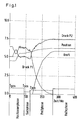
- the ordinate is arbitrarily fixed to the corresponding units.
- the positioning phase which is essentially referred to as overdrive, the pressure medium-operated actuator is pressurized.
- a working cylinder designed according to FIG. 2 is used here by way of example, the piston dividing the cylinder interior into two pressure chambers. To extend the cylinder in one direction, one of the pressures must be increased and the other reduced. Therefore, the pressure profiles of pressure 1 and pressure 2 run in opposite directions.
- the pressure level in cylinder space Z1 is lowered, whereas the pressure in cylinder space 2 increases accordingly in one direction for extension.
- the zoning can also be redefined, since the system is adaptive. If the actuator now reaches the limit of the positioning phase, in this example it goes into a second phase, the so-called search phase. In this search phase, position-dependent and / or speed-dependent regulation takes place, but only with small changes in location. This can now be seen by comparing the position curve shown in FIG. 1.
- the position profile in the pressing phase only has a small gradient, whereas the pressure profiles of pressure P1 and pressure P2 have large gradients. It is clear from this that due to the correspondingly large pressure gradients compared to the relatively small position gradient, taking pressure into account is much more sensitive than determining the position in this area.
- the elasticity of the system elements is then taken into account in this pressing phase.
- the pressure gradients of pressure P1 and pressure P2 become zero, and thus the elastic range is exhausted.
- the welding process can be influenced in this holding phase.
- This welding process can then be regulated in a pressure-controlled manner either as a function of time or as an event. For example, it is possible to either determine the welding duration or to influence the individual welding phases that are present in the welding process.
- the electrodes first hit the workpiece.
- the electrode and the workpiece remain in the heating state, that is to say in the solid state, up to the moment of ignition and even beyond. If the melting point is reached after a short time, the electrode and the workpiece melt in the contact area so that the electrodes no longer have a firm resistance. This transition into the liquid phase can be recognized in the present method by a change in position, so that the contact pressure of the electrodes can be changed. This leads to a considerable increase in the quality of the welded joints.
- the term “... in the holding phase is regulated depending on time and / or event " means exactly such a procedure.
- FIG. 2 shows an example of a structure in which the invention goes according to the device and method.
- a working cylinder with a piston 1 and a piston rod 2 is shown, which is guided in a working cylinder and divides the cylinder space there into the pressure spaces Z1 and Z2.
- the piston extends piston rod 3 to contact point 4.
- this represents an electrode actuation in welding robots.
- the workpieces to be welded would have to be inserted between the tip of the piston rod 3 and the contact point 4. If the piston is now to extend the piston rod 3 or the electrode into the contact position, the cylinder space Z2 is pressurized via the working line A2 and the valve V2, that is to say vented.
- the pressure chamber 1 is then more or less vented at high speed at this moment.
- the piston 1 is braked by applying pressure to the pressure chamber Z1 via the valve V1, that is to say by venting it.
- the piston position is determined using an indicated position determination or measuring system M1.
- Valves V1 and V2 are pressure servo valves with integrated pressure sensors.
- a small change in position takes place for the reasons mentioned above for the elasticity of the system elements 2.
- the monitored pressure values and the control of the servo valves are carried out via a digital controller DR, which is in correspondence with a PLC.
- the pressure values of the valves V1 and V2 and the position values from the measuring system M1 are fed into the digital controller.
- the corresponding control signals for the servo valves are output.
- the pressure medium inlet of valves V1 and V2 is labeled P and the two working lines are labeled A1 and A2.
- FIG 3 shows an overview of the structure of the control loop again.
- the pressure regulator 10 is represented, representing valve and cylinder volume to be controlled, a black box with the designation 20 and a further black box 30 taking into account the piston position and the mass. All values come together in the positioning controller 40.
- the actual position value at the summation point S1 is superimposed on the position setpoint in terms of control technology and goes as a difference into the positioning controller 40. This determines a pressure setpoint which is present at a second control technology summation point S2.
Landscapes
- Engineering & Computer Science (AREA)
- Physics & Mathematics (AREA)
- Mechanical Engineering (AREA)
- General Physics & Mathematics (AREA)
- Automation & Control Theory (AREA)
- Fluid Mechanics (AREA)
- General Engineering & Computer Science (AREA)
- Resistance Welding (AREA)
Applications Claiming Priority (2)
| Application Number | Priority Date | Filing Date | Title |
|---|---|---|---|
| DE4319022A DE4319022A1 (de) | 1993-06-01 | 1993-06-01 | Verfahren zum Betrieb eines druckmittelbetriebenen Positionier- oder Greif- bzw. Spannwerkzeuges |
| DE4319022 | 1993-06-01 |
Publications (2)
| Publication Number | Publication Date |
|---|---|
| EP0632202A1 true EP0632202A1 (fr) | 1995-01-04 |
| EP0632202B1 EP0632202B1 (fr) | 1998-04-08 |
Family
ID=6489905
Family Applications (1)
| Application Number | Title | Priority Date | Filing Date |
|---|---|---|---|
| EP94250131A Expired - Lifetime EP0632202B1 (fr) | 1993-06-01 | 1994-05-18 | Procédé pour la mise en oeuvre d'un instrument de positionnement ou de préhension ou de serrage actionné par un medium de tension |
Country Status (3)
| Country | Link |
|---|---|
| US (1) | US5457959A (fr) |
| EP (1) | EP0632202B1 (fr) |
| DE (2) | DE4319022A1 (fr) |
Cited By (2)
| Publication number | Priority date | Publication date | Assignee | Title |
|---|---|---|---|---|
| US7062832B2 (en) | 2003-03-20 | 2006-06-20 | Smc Corporation | High-speed driving method of pressure cylinder |
| EP2839169B1 (fr) | 2012-04-20 | 2020-04-01 | Bimba Manufacturing Company | Système de prédiction d'actionneur |
Families Citing this family (8)
| Publication number | Priority date | Publication date | Assignee | Title |
|---|---|---|---|---|
| US5704268A (en) * | 1995-07-26 | 1998-01-06 | Thermo Fibertek Inc. | Electro-hydraulic shower oscillator for papermaking |
| DE10021744A1 (de) * | 2000-05-04 | 2001-11-15 | Festo Ag & Co | Vorrichtung zur Einstellung des Differenzdrucks in einem Fluidzylinder |
| JP3970864B2 (ja) * | 2004-04-20 | 2007-09-05 | 本田技研工業株式会社 | 接触機構の制御装置 |
| JP4457299B2 (ja) * | 2004-08-19 | 2010-04-28 | Smc株式会社 | エアシリンダの圧力制御方法及び装置 |
| DE102005033786B3 (de) * | 2005-07-20 | 2007-04-12 | Rexroth Mecman Gmbh | Elektropneumatische Druckmittelmengensteuerung |
| DE102008007651B3 (de) * | 2008-02-06 | 2009-09-24 | Samson Aktiengesellschaft | Stellungsregler für doppeltwirkenden, pneumatischen Stellantrieb, doppeltwirkender, pneumatischer Stellantrieb und Verfahren zum Betreiben des doppeltwirkenden, pneumatischen Stellantriebs |
| WO2009133956A1 (fr) * | 2008-05-02 | 2009-11-05 | 国立大学法人筑波大学 | Actionneur, procédé de commande d’actionneur et programme de commande d’actionneur |
| DE102019210599A1 (de) * | 2019-07-18 | 2021-01-21 | Festo Se & Co. Kg | Reglervorrichtung, fluidisches System und Verfahren zur Regelung eines fluidischen Aktors |
Citations (1)
| Publication number | Priority date | Publication date | Assignee | Title |
|---|---|---|---|---|
| DE2937998A1 (de) * | 1979-09-20 | 1981-04-02 | Beche & Grohs GmbH, 5609 Hückeswagen | Verfahren zur steuerung des arbeitsablaufes einer druckmittelbeaufschlagten arbeitsmaschine sowie druckmittelbeauschlagte arbeitsmaschine mit druckmittelsteuerung |
Family Cites Families (7)
| Publication number | Priority date | Publication date | Assignee | Title |
|---|---|---|---|---|
| US3542274A (en) * | 1968-03-25 | 1970-11-24 | Caterpillar Tractor Co | Speed-programmed friction welder control |
| JPS57192603A (en) * | 1981-05-23 | 1982-11-26 | Shoketsu Kinzoku Kogyo Co Ltd | Fluid pressure cylinder control device |
| DE3642642C3 (de) * | 1986-12-13 | 1994-09-01 | Rexroth Mannesmann Gmbh | Schaltungsanordnung zur Lage- und Vorschubregelung eines hydraulischen Antriebes |
| DE3708989C2 (de) * | 1987-03-19 | 1993-10-14 | Festo Kg | Steuervorrichtung für einen in einem doppeltwirkenden Zylinder verschiebbaren Kolben |
| US5012722A (en) * | 1989-11-06 | 1991-05-07 | International Servo Systems, Inc. | Floating coil servo valve |
| US5111658A (en) * | 1990-02-12 | 1992-05-12 | Linde Aktiengesellschaft | Method of braking a vehicle |
| US5343994A (en) * | 1993-03-23 | 1994-09-06 | Caterpillar Inc. | End of fill detector for a hydraulic clutch |
-
1993
- 1993-06-01 DE DE4319022A patent/DE4319022A1/de not_active Ceased
-
1994
- 1994-05-18 EP EP94250131A patent/EP0632202B1/fr not_active Expired - Lifetime
- 1994-05-18 DE DE59405615T patent/DE59405615D1/de not_active Expired - Fee Related
- 1994-05-31 US US08/251,518 patent/US5457959A/en not_active Expired - Fee Related
Patent Citations (1)
| Publication number | Priority date | Publication date | Assignee | Title |
|---|---|---|---|---|
| DE2937998A1 (de) * | 1979-09-20 | 1981-04-02 | Beche & Grohs GmbH, 5609 Hückeswagen | Verfahren zur steuerung des arbeitsablaufes einer druckmittelbeaufschlagten arbeitsmaschine sowie druckmittelbeauschlagte arbeitsmaschine mit druckmittelsteuerung |
Cited By (4)
| Publication number | Priority date | Publication date | Assignee | Title |
|---|---|---|---|---|
| US7062832B2 (en) | 2003-03-20 | 2006-06-20 | Smc Corporation | High-speed driving method of pressure cylinder |
| EP2839169B1 (fr) | 2012-04-20 | 2020-04-01 | Bimba Manufacturing Company | Système de prédiction d'actionneur |
| US11572904B2 (en) | 2012-04-20 | 2023-02-07 | Bimba Llc | Actuator predictive system |
| US11879484B2 (en) | 2012-04-20 | 2024-01-23 | Bimba Llc | Actuator predictive system |
Also Published As
| Publication number | Publication date |
|---|---|
| EP0632202B1 (fr) | 1998-04-08 |
| DE4319022A1 (de) | 1994-12-08 |
| DE59405615D1 (de) | 1998-05-14 |
| US5457959A (en) | 1995-10-17 |
Similar Documents
| Publication | Publication Date | Title |
|---|---|---|
| DE3708989C2 (de) | Steuervorrichtung für einen in einem doppeltwirkenden Zylinder verschiebbaren Kolben | |
| DE102005014416B4 (de) | Luftservozylindervorrichtung und Steuerverfahren hierfür | |
| DE102004012294B4 (de) | Hochgeschwindigkeitsantriebsverfahren und -system für Druckzylinder | |
| EP2105280B1 (fr) | Procédé d'utilisation d'un outil de soudure par ultrasons doté d'un entraînement fluidique | |
| EP1830979B1 (fr) | Procede pour commander une unite a cylindre de compensation destinee en particulier a un dispositif de soudure | |
| EP0288878B1 (fr) | Procédé de revêtement automatique de pièces en série | |
| DE2442865A1 (de) | Programmierbare vorrichtung zur mechanischen ausfuehrung von arbeitsgaengen | |
| EP0687211B1 (fr) | Systeme de regulation pour pince porte-electrodes | |
| EP0632202B1 (fr) | Procédé pour la mise en oeuvre d'un instrument de positionnement ou de préhension ou de serrage actionné par un medium de tension | |
| EP1882102B1 (fr) | Mecanisme d'entrainement a commande fluidique et procede de commande correspondant | |
| DE10021744A1 (de) | Vorrichtung zur Einstellung des Differenzdrucks in einem Fluidzylinder | |
| DE102017004803A1 (de) | Verfahren zum Betrieb einer Pulverpresse mit Lagenregelung und Pulverpresse zur Ausführung des Verfahrens | |
| DE4111106A1 (de) | Mehrdruck-steueranlage | |
| DE3803632A1 (de) | Mehr-stoessel-schmiedemaschine | |
| DE3521699C2 (de) | Anordnung zum Regeln für steuerbare Pneumatikkissen | |
| DE3929669C2 (de) | Bolzenanschweißvorrichtung | |
| EP1430985B1 (fr) | Pince de soudage comprenant un entraînement linéaire programmable avec deux boucles indépendantes d'asservissement et procédé de commande de l'entraînement linéaire d'une telle pince de soudage | |
| DE19545772A1 (de) | Zylinder-Positionier-Steuergerät | |
| DE4405909A1 (de) | Verfahren und Schaltungsanordnung zum Unterbrechen und Fortführen des Ziehprozesses an zweifachwirkenden Pressen, insbesondere hydraulischen Pressen | |
| EP0284903B1 (fr) | Presse à piston | |
| CH655882A5 (de) | Sicherheitsabschaltvorrichtung an einer zahnradschleifmaschine. | |
| EP0288719B1 (fr) | Dispositif de commande pour installation de puissance pneumatique-hydraulique | |
| DE102020214453B4 (de) | Verfahren zum Betreiben einer Punktschweißzange und Punktschweißzange | |
| CH681244A5 (fr) | ||
| DE3438600C2 (fr) |
Legal Events
| Date | Code | Title | Description |
|---|---|---|---|
| PUAI | Public reference made under article 153(3) epc to a published international application that has entered the european phase |
Free format text: ORIGINAL CODE: 0009012 |
|
| AK | Designated contracting states |
Kind code of ref document: A1 Designated state(s): DE FR GB IT |
|
| 17P | Request for examination filed |
Effective date: 19941212 |
|
| 17Q | First examination report despatched |
Effective date: 19960903 |
|
| GRAG | Despatch of communication of intention to grant |
Free format text: ORIGINAL CODE: EPIDOS AGRA |
|
| GRAG | Despatch of communication of intention to grant |
Free format text: ORIGINAL CODE: EPIDOS AGRA |
|
| GRAH | Despatch of communication of intention to grant a patent |
Free format text: ORIGINAL CODE: EPIDOS IGRA |
|
| GRAH | Despatch of communication of intention to grant a patent |
Free format text: ORIGINAL CODE: EPIDOS IGRA |
|
| GRAH | Despatch of communication of intention to grant a patent |
Free format text: ORIGINAL CODE: EPIDOS IGRA |
|
| GRAA | (expected) grant |
Free format text: ORIGINAL CODE: 0009210 |
|
| AK | Designated contracting states |
Kind code of ref document: B1 Designated state(s): DE FR GB IT |
|
| PG25 | Lapsed in a contracting state [announced via postgrant information from national office to epo] |
Ref country code: IT Free format text: LAPSE BECAUSE OF FAILURE TO SUBMIT A TRANSLATION OF THE DESCRIPTION OR TO PAY THE FEE WITHIN THE PRE;WARNING: LAPSES OF ITALIAN PATENTS WITH EFFECTIVE DATE BEFORE 2007 MAY HAVE OCCURRED AT ANY TIME BEFORE 2007. THE CORRECT EFFECTIVE DATE MAY BE DIFFERENT FROM THE ONE RECORDED.SCRIBED TIME-LIMIT Effective date: 19980408 Ref country code: GB Free format text: LAPSE BECAUSE OF FAILURE TO SUBMIT A TRANSLATION OF THE DESCRIPTION OR TO PAY THE FEE WITHIN THE PRESCRIBED TIME-LIMIT Effective date: 19980408 Ref country code: FR Free format text: LAPSE BECAUSE OF FAILURE TO SUBMIT A TRANSLATION OF THE DESCRIPTION OR TO PAY THE FEE WITHIN THE PRESCRIBED TIME-LIMIT Effective date: 19980408 |
|
| REF | Corresponds to: |
Ref document number: 59405615 Country of ref document: DE Date of ref document: 19980514 |
|
| EN | Fr: translation not filed | ||
| GBV | Gb: ep patent (uk) treated as always having been void in accordance with gb section 77(7)/1977 [no translation filed] |
Effective date: 19980408 |
|
| PLBE | No opposition filed within time limit |
Free format text: ORIGINAL CODE: 0009261 |
|
| STAA | Information on the status of an ep patent application or granted ep patent |
Free format text: STATUS: NO OPPOSITION FILED WITHIN TIME LIMIT |
|
| 26N | No opposition filed | ||
| PGFP | Annual fee paid to national office [announced via postgrant information from national office to epo] |
Ref country code: DE Payment date: 20010726 Year of fee payment: 8 |
|
| PG25 | Lapsed in a contracting state [announced via postgrant information from national office to epo] |
Ref country code: DE Free format text: LAPSE BECAUSE OF NON-PAYMENT OF DUE FEES Effective date: 20021203 |