EP0632202A1 - Process for the operation of a pressure medium actuated positioner or gripping clamping device - Google Patents
Process for the operation of a pressure medium actuated positioner or gripping clamping device Download PDFInfo
- Publication number
- EP0632202A1 EP0632202A1 EP94250131A EP94250131A EP0632202A1 EP 0632202 A1 EP0632202 A1 EP 0632202A1 EP 94250131 A EP94250131 A EP 94250131A EP 94250131 A EP94250131 A EP 94250131A EP 0632202 A1 EP0632202 A1 EP 0632202A1
- Authority
- EP
- European Patent Office
- Prior art keywords
- pressure
- positioning
- pressure medium
- zone
- gripping
- Prior art date
- Legal status (The legal status is an assumption and is not a legal conclusion. Google has not performed a legal analysis and makes no representation as to the accuracy of the status listed.)
- Granted
Links
Images


Classifications
-
- F—MECHANICAL ENGINEERING; LIGHTING; HEATING; WEAPONS; BLASTING
- F15—FLUID-PRESSURE ACTUATORS; HYDRAULICS OR PNEUMATICS IN GENERAL
- F15B—SYSTEMS ACTING BY MEANS OF FLUIDS IN GENERAL; FLUID-PRESSURE ACTUATORS, e.g. SERVOMOTORS; DETAILS OF FLUID-PRESSURE SYSTEMS, NOT OTHERWISE PROVIDED FOR
- F15B15/00—Fluid-actuated devices for displacing a member from one position to another; Gearing associated therewith
- F15B15/20—Other details, e.g. assembly with regulating devices
- F15B15/28—Means for indicating the position, e.g. end of stroke
-
- B—PERFORMING OPERATIONS; TRANSPORTING
- B23—MACHINE TOOLS; METAL-WORKING NOT OTHERWISE PROVIDED FOR
- B23Q—DETAILS, COMPONENTS, OR ACCESSORIES FOR MACHINE TOOLS, e.g. ARRANGEMENTS FOR COPYING OR CONTROLLING; MACHINE TOOLS IN GENERAL CHARACTERISED BY THE CONSTRUCTION OF PARTICULAR DETAILS OR COMPONENTS; COMBINATIONS OR ASSOCIATIONS OF METAL-WORKING MACHINES, NOT DIRECTED TO A PARTICULAR RESULT
- B23Q15/00—Automatic control or regulation of feed movement, cutting velocity or position of tool or work
- B23Q15/20—Automatic control or regulation of feed movement, cutting velocity or position of tool or work before or after the tool acts upon the workpiece
- B23Q15/22—Control or regulation of position of tool or workpiece
- B23Q15/24—Control or regulation of position of tool or workpiece of linear position
-
- G—PHYSICS
- G05—CONTROLLING; REGULATING
- G05D—SYSTEMS FOR CONTROLLING OR REGULATING NON-ELECTRIC VARIABLES
- G05D3/00—Control of position or direction
- G05D3/12—Control of position or direction using feedback
- G05D3/14—Control of position or direction using feedback using an analogue comparing device
- G05D3/1445—Control of position or direction using feedback using an analogue comparing device with a plurality of loops
-
- G—PHYSICS
- G05—CONTROLLING; REGULATING
- G05B—CONTROL OR REGULATING SYSTEMS IN GENERAL; FUNCTIONAL ELEMENTS OF SUCH SYSTEMS; MONITORING OR TESTING ARRANGEMENTS FOR SUCH SYSTEMS OR ELEMENTS
- G05B2219/00—Program-control systems
- G05B2219/30—Nc systems
- G05B2219/41—Servomotor, servo controller till figures
- G05B2219/41309—Hydraulic or pneumatic drive
-
- G—PHYSICS
- G05—CONTROLLING; REGULATING
- G05B—CONTROL OR REGULATING SYSTEMS IN GENERAL; FUNCTIONAL ELEMENTS OF SUCH SYSTEMS; MONITORING OR TESTING ARRANGEMENTS FOR SUCH SYSTEMS OR ELEMENTS
- G05B2219/00—Program-control systems
- G05B2219/30—Nc systems
- G05B2219/42—Servomotor, servo controller kind till VSS
- G05B2219/42123—Position loop then force, current loop
Definitions
- the invention relates to a method for operating a pressure medium-operated positioning or gripping tool and a pressure medium-operated positioning or gripping or clamping tool according to the preamble of claims 1 and 8.
- Pressure medium-operated positioning or gripping or clamping tools are widely known from the prior art.
- the position of an actuator is determined and, depending on the position, the valve-actuated pressure medium supply to the actuator is regulated.
- the actuator is often allowed to move abruptly into the end position for the purpose of quick, time-saving starting of the tool, in which the remaining kinetic energy must then be absorbed. This leads to increased wear.
- the target position is approached in a controlled manner, such a shock in the end position is reduced, but this leads to a longer positioning time.
- the effect is that the welding electrodes yield in the target position with increased application of force.
- the elasticity of the system elements with regard to the target position control is not taken into account.
- the invention is therefore based on the object, in a method and in a tool of the generic type, to take into account the elasticity of the system elements in the target position and to be able to be influenced after reaching the target position, in particular when actuating welding guns in welding robots.
- the solution according to the invention with regard to the method consists in that, in addition to the position-dependent regulated pressure medium supply, the pressure of the pressure medium is included in the regulation of the valve-operated pressure medium supply.
- the zoning determines at which point in time or at which position pressure-dependent or position-dependent control is used.
- position-dependent regulated means that the pressure medium supply depends on that of Path or position determination system determined position value is regulated.
- the travel path intended for a positioning task after the travel path intended for a positioning task has been recorded for the first time, it is divided into different zones.
- a differentiated assessment of the intended travel path is already carried out, which will later be regulated depending on the zone. This leads to a time optimization of the positioning task.
- the actuating path is divided into at least two zones, the first zone being from a starting position S pos to a freely selectable tolerance limit T pos near a target position Z pos and the second zone being from the tolerance limit T pos to the target zone Z pos extends.
- the pressure medium supply to the actuator in the first zone is then largely controlled as a function of position and in the second zone essentially as a function of pressure. The result of this is that the first zone essentially serves to run through an overdrive in order to reach the target position as quickly as possible. Shortly before the target position, there is then only pressure-dependent regulation, which can otherwise take place in a braked form.
- this second zone is again divided into two sub-zones, the pressure medium supply in the first sub-zone being regulated largely as a function of position in the region from T pos and only in a pressure-dependent manner in the second sub-zone to Z pos .
- the parameter storage of the zone division, as well as the position and pressure values can be done adaptively for repetitive positioning tasks.
- the pressure medium supply is regulated as a function of time and / or event. Due to the exclusively pressure-dependent controlled pressure medium supply in the last phase in Area of the target position is achieved that the shock is drastically reduced when reaching the target position.
- the pressure-dependent control in particular in the last phase of the positioning path, can be clearly recognized by evaluating the pressure curve at which point of the closing process, for example, contact the electrodes of the welding robot on the workpiece. Since the method is designed to be adaptive, the travel path is determined and the target position is recognized when the positioning task is carried out for the first time. After that, a concrete distinction can be made between reaching the target position, i.e. hitting the electrodes, and bending the individual holding elements. This then leads to the further advantage that in this phase, after the electrodes have hit the elastic phase, it can be recognized and used, for example, to regulate the contact pressure of the electrodes.
- the holding phase referred to in a further embodiment can then be regulated as a function of time and / or event. It is also advantageous here that a high spatial resolution of the position-determining device can be dispensed with, and the position-determining device can thus be simpler.
- the position determination system In the area of the actual overdrive, ie the rough positioning of the end position, it is important that the position determination system can cover a long way. In the second phase, it would be important for a position determination device, such as is used in known methods and devices, for the position determination system to have such a high spatial resolution that the small changes in location in the region near the target position or possibly in the elastic region of the system elements are sufficiently precise. As already mentioned above, the path or position determination systems must therefore be of high quality and therefore be complex.
- the position determination system is used essentially only for running through the overdrive, possibly also for the search phase, and therefore does not require a high spatial resolution, and that the further one is in the area of the target position or in the area of elasticity Regulation takes place depending on the pressure.
- the position determination system can be designed to be correspondingly simple, and by using the pressure-dependent positioning, the positioning in the elastic range is extremely sensitive.
- the attachment of pressure measuring elements is unproblematic and can be done in a simple manner by integration in valves or in the corresponding pressure lines.
- means are provided according to the invention for pressure detection of the pressure medium in the area of the pressure medium supply to the actuator. These can either be in the pressure medium supply system or in the part on the working line side the valves may be arranged. This means that a differentiated regulation in distinguishing the two states a) position change is registered since the target position has not yet been reached, and b) target position reached, position change due to elastic yielding of the individual elements, given.
- the point of impact of the electrodes can be "learned" after the first pass, so that there is no constant “bang” in the target position during subsequent continuous operation. Overall, the whole regulation is also time-optimized.
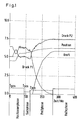
- the ordinate is arbitrarily fixed to the corresponding units.
- the positioning phase which is essentially referred to as overdrive, the pressure medium-operated actuator is pressurized.
- a working cylinder designed according to FIG. 2 is used here by way of example, the piston dividing the cylinder interior into two pressure chambers. To extend the cylinder in one direction, one of the pressures must be increased and the other reduced. Therefore, the pressure profiles of pressure 1 and pressure 2 run in opposite directions.
- the pressure level in cylinder space Z1 is lowered, whereas the pressure in cylinder space 2 increases accordingly in one direction for extension.
- the zoning can also be redefined, since the system is adaptive. If the actuator now reaches the limit of the positioning phase, in this example it goes into a second phase, the so-called search phase. In this search phase, position-dependent and / or speed-dependent regulation takes place, but only with small changes in location. This can now be seen by comparing the position curve shown in FIG. 1.
- the position profile in the pressing phase only has a small gradient, whereas the pressure profiles of pressure P1 and pressure P2 have large gradients. It is clear from this that due to the correspondingly large pressure gradients compared to the relatively small position gradient, taking pressure into account is much more sensitive than determining the position in this area.
- the elasticity of the system elements is then taken into account in this pressing phase.
- the pressure gradients of pressure P1 and pressure P2 become zero, and thus the elastic range is exhausted.
- the welding process can be influenced in this holding phase.
- This welding process can then be regulated in a pressure-controlled manner either as a function of time or as an event. For example, it is possible to either determine the welding duration or to influence the individual welding phases that are present in the welding process.
- the electrodes first hit the workpiece.
- the electrode and the workpiece remain in the heating state, that is to say in the solid state, up to the moment of ignition and even beyond. If the melting point is reached after a short time, the electrode and the workpiece melt in the contact area so that the electrodes no longer have a firm resistance. This transition into the liquid phase can be recognized in the present method by a change in position, so that the contact pressure of the electrodes can be changed. This leads to a considerable increase in the quality of the welded joints.
- the term “... in the holding phase is regulated depending on time and / or event " means exactly such a procedure.
- FIG. 2 shows an example of a structure in which the invention goes according to the device and method.
- a working cylinder with a piston 1 and a piston rod 2 is shown, which is guided in a working cylinder and divides the cylinder space there into the pressure spaces Z1 and Z2.
- the piston extends piston rod 3 to contact point 4.
- this represents an electrode actuation in welding robots.
- the workpieces to be welded would have to be inserted between the tip of the piston rod 3 and the contact point 4. If the piston is now to extend the piston rod 3 or the electrode into the contact position, the cylinder space Z2 is pressurized via the working line A2 and the valve V2, that is to say vented.
- the pressure chamber 1 is then more or less vented at high speed at this moment.
- the piston 1 is braked by applying pressure to the pressure chamber Z1 via the valve V1, that is to say by venting it.
- the piston position is determined using an indicated position determination or measuring system M1.
- Valves V1 and V2 are pressure servo valves with integrated pressure sensors.
- a small change in position takes place for the reasons mentioned above for the elasticity of the system elements 2.
- the monitored pressure values and the control of the servo valves are carried out via a digital controller DR, which is in correspondence with a PLC.
- the pressure values of the valves V1 and V2 and the position values from the measuring system M1 are fed into the digital controller.
- the corresponding control signals for the servo valves are output.
- the pressure medium inlet of valves V1 and V2 is labeled P and the two working lines are labeled A1 and A2.
- FIG 3 shows an overview of the structure of the control loop again.
- the pressure regulator 10 is represented, representing valve and cylinder volume to be controlled, a black box with the designation 20 and a further black box 30 taking into account the piston position and the mass. All values come together in the positioning controller 40.
- the actual position value at the summation point S1 is superimposed on the position setpoint in terms of control technology and goes as a difference into the positioning controller 40. This determines a pressure setpoint which is present at a second control technology summation point S2.
Abstract
Description
Die Erfindung betrifft ein Verfahren zum Betrieb eines druckmittelbetriebenen Positionier- oder Greifwerkzeuges sowie ein druckmittelbetriebenes Positionier- oder Greif- bzw. Spannwerkzeug gemäß Oberbegriff der Patentansprüche 1 und 8.The invention relates to a method for operating a pressure medium-operated positioning or gripping tool and a pressure medium-operated positioning or gripping or clamping tool according to the preamble of
Druckmittelbetriebene Positionier oder Greif- bzw. Spannwerkzeuge sind aus dem Stand der Technik vielfach bekannt. Dabei wird die Position eines Stellorganes ermittelt und positionsabhängig die ventilbetätigte Druckmittelzufuhr zum Stellorgan geregelt. Bei Verfahren sowie Einrichtungen bekannter Art läßt man oftmals das Stellorgan zum Zwecke eines schnellen zeitsparenden Anstellens des Werkzeuges, stoßartig in Endposition fahren, in der dann die restliche kinetische Energie aufgenommen werden muß. Dies führt dabei zu erhöhtem Verschleiß. Bei einem geregelten Anfahren der Zielposition wird ein solcher Stoß in Endposition zwar vermindert, jedoch führt dies zu einer längeren Positionierdauer.Pressure medium-operated positioning or gripping or clamping tools are widely known from the prior art. The position of an actuator is determined and, depending on the position, the valve-actuated pressure medium supply to the actuator is regulated. In methods and devices of a known type, the actuator is often allowed to move abruptly into the end position for the purpose of quick, time-saving starting of the tool, in which the remaining kinetic energy must then be absorbed. This leads to increased wear. When the target position is approached in a controlled manner, such a shock in the end position is reduced, but this leads to a longer positioning time.
Bei speziellen Anwendungen, beispielsweise bei Schweißzangenbetätigungen an Schweißrobotern hat man den Effekt, daß die Schweißelektroden in Zielposition unter erhöhter Kraftanwendung nachgeben. Bei bekannten Einrichtungen sowie Verfahren zur Schweißzangenbetätigung bei Robotern werden die Anlagenelemente in ihrer Elastizität hinsichtlich der Zielpositionansteuerung nicht berücksichtigt.In special applications, for example in welding gun actuation on welding robots, the effect is that the welding electrodes yield in the target position with increased application of force. In known devices and methods for actuating welding guns in robots, the elasticity of the system elements with regard to the target position control is not taken into account.
Der Erfindung liegt daher die Aufgabe zugrunde, bei einem Verfahren sowie bei einem Werkzeug der gattungsgemäßen Art eine Mitberücksichtigung der Elastizität der Anlagenelemente in der Zielposition sowie eine Beeinflußbarkeit nach Erreichen der Zielposition insbesondere bei der Schweißzangenbetätigung in Schweißrobotern zu ermöglichen.The invention is therefore based on the object, in a method and in a tool of the generic type, to take into account the elasticity of the system elements in the target position and to be able to be influenced after reaching the target position, in particular when actuating welding guns in welding robots.
Die gestellte Aufgabe ist hinsichtlich eines Verfahrens der gattungsgemäßen Art erfindungsgemäß durch die kennzeichnenden Merkmale des Patentanspruches 1 gelöst. Hinsichtlich eines druckmittelbetriebenen Positionier- oder Greif- bzw. Spannwerkzeuges gemäß Oberbegriff des Patentanspruches 8 ist die gestellte Aufgabe erfindungsgemäß durch das kennzeichnende Merkmal des Patentanspruches 8 gelöst. Weitere vorteilhafte Ausgestaltungen hinsichtlich des Verfahrens sowie hinsichtlich des Werkzeuges sind in den Unteransprüchen angegeben.The stated object is achieved according to the invention with respect to a method of the generic type by the characterizing features of
Die erfindungsgemäße Lösung hinsichtlich des Verfahrens besteht darin, daß zusätzlich zur positionsabhängig geregelten Druckmittelzufuhr der Druck des Druckmittels in die Regelung der ventilbetätigten Druckmittelzufuhr eingeht. Zu welchem Zeitpunkt bzw. bei welcher Position druckabhängig oder positionsabhängig geregelt wird, ist durch die Zoneneinteilung bestimmt. Die Bezeichnung "positionsabhängig" geregelt bedeutet, daß die Druckmittelzufuhr abhängig von dem vom Weg- bzw. Positionsermittlungssystem ermittelten Positionswert geregelt wird.The solution according to the invention with regard to the method consists in that, in addition to the position-dependent regulated pressure medium supply, the pressure of the pressure medium is included in the regulation of the valve-operated pressure medium supply. The zoning determines at which point in time or at which position pressure-dependent or position-dependent control is used. The term "position-dependent" regulated means that the pressure medium supply depends on that of Path or position determination system determined position value is regulated.
In weiterer Ausgestaltung des Verfahrens wird daher nach erstmaliger Erfassung des für eine Postionieraufgabe vorgesehenen Stellweges derselbe in verschiedene Zonen eingeteilt. Hier erfolgt bereits eine differenzierte Bewertung des vorgesehenen Stellweges, bei dem dann später zonenabhängig geregelt wird. Dies führt zu einer Zeitoptimierung der Positionieraufgabe.In a further embodiment of the method, therefore, after the travel path intended for a positioning task has been recorded for the first time, it is divided into different zones. Here, a differentiated assessment of the intended travel path is already carried out, which will later be regulated depending on the zone. This leads to a time optimization of the positioning task.
In weiterer Ausgestaltung ist der Stellweg in mindestens zwei Zonen eingeteilt, wobei sich die erste Zone von einer Startpostition Spos bis zu einer frei wählbaren Toleranzgrenze Tpos nahe einer Zielposition Zpos und die zweite Zone sich von der Toleranzgrenze Tpos bis zur Zielzone Zpos erstreckt. Dabei wird dann die Druckmittelzufuhr zum Stellorgan in der ersten Zone weitgehend positionsabhängig und in der zweiten Zone im wesentlichen druckabhängig geregelt. Dies hat zur Folge, daß die erste Zone im wesentlichen zum Durchlaufen eines Schnellganges dient, um die Zielposition möglichst schnell zu erreichen. Kurz vor der Zielposition erfolgt dann nur noch eine druckabhängige Regelung die dabei im übrigen in gebremster Form von statten gehen kann. In weiterer Ausgestaltung der Erfindung ist jedoch diese zweite Zone nochmals in zwei Teilzonen eingeteilt, wobei die Druckmittelzufuhr in der ersten Teilzone im Bereich von Tpos weitgehend positionsabhängig und in der zweiten Teilzone bis Zpos nur druckabhängig geregelt wird. Die Parameterabspeicherung der Zoneneinteilung, sowie der Positions- und Druckwerte kann bei sich wiederholenden Positionieraufgaben adaptiv erfolgen. In weiterer Ausgestaltung folgt nach Erreichen der Zielposition eine Haltephase, in welcher die Druckmittelzufuhr zeit- und/oder ereignisabhängig geregelt wird. Durch die ausschließlich druckabhängig geregelte Druckmittelzufuhr in der letzten Phase im Bereich der Zielposition wird erreicht, daß der Stoß beim Erreichen der Zielposition drastisch gemindert wird. Bei Elektrodenbetätigungen von Schweißrobotern ergibt sich das Problem, daß die Elektroden samt Halter nach Erreichen der "Kontaktposition" apparativ und geometrisch bedingt nachfedern. Je nach Anlenkung der Schweißzangenelemente registriert die Positionserfassung am Stellorgan dennoch eine Positionsänderung. Dies würde bei herkömmlichen Regelverfahren sowie Einrichtungen dazu führen, daß das Stellorgan weiterhin mit einer Stellgröße beaufschlagt wird. Bei bekannten Verfahren und Einrichtungen würde dies solange erfolgen, bis die einzelnen Elemente mechanisch nicht weiter nachgeben. Ein durch eine solche Vorgehensweise resultierender Verschleiß ist bei der erfindungsgemäßen Lösung hingegen vermieden. Außerdem kann bei bekannten Einrichtungen gerade diese "elastische" Zone technisch nicht genutzt werden, um beispielsweise den Anpreßdruck während des Schweißvorganges zu regeln. Durch die druckabhängige Regelung, insbesondere in der letzten Phase des Positionierweges, kann durch Bewertung des Druckverlaufes eindeutig erkannt werden, an welchem Punkt des Schließvorganges beispielsweise die Elektroden des Schweißroboters am Werkstück kontaktieren. Da das Verfahren adaptiv angelegt ist, wird bei erstmaliger Erfassung beim Durchlaufen der Positionieraufgabe der Stellweg festgelegt und die Zielposition erkannt. Danach kann eine konkrete Unterscheidung zwischen Erreichen der Zielposition, also Auftreffen der Elektroden, und Durchbiegen der einzelnen Halteelemente vorgenommen werden. Dies führt dann im weiteren zu dem Vorteil, daß gerade in dieser Phase nach Auftreffen der Elektroden die elastische Phase erkannt und beispielsweise zur Regelung des Anpressdruckes der Elektroden herangezogen werden kann. Die in weiterer Ausgestaltung bezeichnete Haltephase kann dann zeit- und/oder ereignisabhängig geregelt werden. Vorteilhaft ist hierbei ebenfalls, daß man auf eine hohe Ortsauflösung der Positionsermittlungseinrichtung verzichten kann, und die Positionsermittlungseinrichtung somit einfacher sein kann.In a further embodiment, the actuating path is divided into at least two zones, the first zone being from a starting position S pos to a freely selectable tolerance limit T pos near a target position Z pos and the second zone being from the tolerance limit T pos to the target zone Z pos extends. The pressure medium supply to the actuator in the first zone is then largely controlled as a function of position and in the second zone essentially as a function of pressure. The result of this is that the first zone essentially serves to run through an overdrive in order to reach the target position as quickly as possible. Shortly before the target position, there is then only pressure-dependent regulation, which can otherwise take place in a braked form. In a further embodiment of the invention, however, this second zone is again divided into two sub-zones, the pressure medium supply in the first sub-zone being regulated largely as a function of position in the region from T pos and only in a pressure-dependent manner in the second sub-zone to Z pos . The parameter storage of the zone division, as well as the position and pressure values can be done adaptively for repetitive positioning tasks. In a further embodiment, after the target position has been reached, there is a holding phase in which the pressure medium supply is regulated as a function of time and / or event. Due to the exclusively pressure-dependent controlled pressure medium supply in the last phase in Area of the target position is achieved that the shock is drastically reduced when reaching the target position. When actuating electrodes of welding robots, the problem arises that the electrodes and holder spring back after reaching the "contact position" due to the apparatus and geometry. Depending on the articulation of the welding gun elements, the position detection on the actuator still registers a change in position. In the case of conventional control methods and devices, this would result in the actuating element still being subjected to a manipulated variable. In the case of known methods and devices, this would take place until the individual elements no longer yield mechanically. However, wear resulting from such a procedure is avoided in the solution according to the invention. In addition, this "elastic" zone cannot be used technically in known devices, for example in order to regulate the contact pressure during the welding process. The pressure-dependent control, in particular in the last phase of the positioning path, can be clearly recognized by evaluating the pressure curve at which point of the closing process, for example, contact the electrodes of the welding robot on the workpiece. Since the method is designed to be adaptive, the travel path is determined and the target position is recognized when the positioning task is carried out for the first time. After that, a concrete distinction can be made between reaching the target position, i.e. hitting the electrodes, and bending the individual holding elements. This then leads to the further advantage that in this phase, after the electrodes have hit the elastic phase, it can be recognized and used, for example, to regulate the contact pressure of the electrodes. The holding phase referred to in a further embodiment can then be regulated as a function of time and / or event. It is also advantageous here that a high spatial resolution of the position-determining device can be dispensed with, and the position-determining device can thus be simpler.
Dies ergibt sich aus folgendem Grund.
Im Bereich des eigentlichen Schnellganges, also des groben Anpositionierens der Endposition kommt es darauf an, daß das Positionsermittlungssystem einen großen Weg erfassen kann. In der zweiten Phase käme es bei einer Positionsermittlungseinrichtung, wie sie bei bekannten Verfahren und Einrichtungen verwendet wird darauf an, daß das Positionsermittlungssystem eine solch hohe Ortsauflösung aufweist, daß die kleinen Ortsänderungen im Bereich nahe der Zielposition oder möglicherweise im Elastizitätsbereich der Anlagenelemente hinreichend genau ist. Wie oben bereits gesagt, müssen die Weg- bzw. Positionsermittlungssysteme daher von großer Güte, und damit aufwendig sein. Bei der vorliegenden Erfindung ergibt sich dagegen der Vorteil, daß das Positionsermittlungssystem im wesentlichen nur für das Durchlaufen des Schnellganges, möglicherweise auch noch für die Suchphase herangezogen wird, und daher keine hohe Ortsauflösung braucht, und daß im Bereich der Zielposition bzw. im Elastizitätsbereiches die weitere Regelung druckabhängig erfolgt. Das heißt das Postionsermittlungssystem kann entsprechend einfach ausgebildet sein, und durch die Zuhilfenahme der druckabhängigen Positionierung ist die Positionierung im elastischen Bereich extrem feinfühlig. Die Anbringung von Druckmeßelementen ist unproblematisch und kann auf einfache Weise durch die Integration in Ventile oder in die entsprechenden Druckleitungen erfolgen.This is because of the following reason.
In the area of the actual overdrive, ie the rough positioning of the end position, it is important that the position determination system can cover a long way. In the second phase, it would be important for a position determination device, such as is used in known methods and devices, for the position determination system to have such a high spatial resolution that the small changes in location in the region near the target position or possibly in the elastic region of the system elements are sufficiently precise. As already mentioned above, the path or position determination systems must therefore be of high quality and therefore be complex. In the present invention, on the other hand, there is the advantage that the position determination system is used essentially only for running through the overdrive, possibly also for the search phase, and therefore does not require a high spatial resolution, and that the further one is in the area of the target position or in the area of elasticity Regulation takes place depending on the pressure. This means that the position determination system can be designed to be correspondingly simple, and by using the pressure-dependent positioning, the positioning in the elastic range is extremely sensitive. The attachment of pressure measuring elements is unproblematic and can be done in a simple manner by integration in valves or in the corresponding pressure lines.
Hinsichtlich eines druckmittelbetriebenen Positionier- oder Greif- bzw. Spannwerkzeuges gemäß Oberbegriff des Patentanspruches 8 sind erfindungsgemäß Mittel zur Druckerfassung des Druckmittels im Bereich der Druckmittelzufuhr zum Stellorgan vorgesehen. Diese können wahlweise im Druckmittelzuleitungssystem aber auch im arbeitsleitungsseitigen Teil der Ventile angeordnet sein. Hiermit ist also eine differenzierte Regelung in Unterscheidung der beiden Zustände a) Positionsänderung registriert da Zielposition noch nicht erreicht, und
b) Zielposition erreicht, Positionsänderung wegen elastischem Nachgeben der einzelnen Elemente,
gegeben.With regard to a pressure medium-operated positioning or gripping or tensioning tool according to the preamble of claim 8, means are provided according to the invention for pressure detection of the pressure medium in the area of the pressure medium supply to the actuator. These can either be in the pressure medium supply system or in the part on the working line side the valves may be arranged. This means that a differentiated regulation in distinguishing the two states a) position change is registered since the target position has not yet been reached, and
b) target position reached, position change due to elastic yielding of the individual elements,
given.
Außerdem kann der Auftreffpunkt der Elektroden nach erstmaligen Durchlauf "gelernt" werden, so daß beim nachfolgenden Dauerbetrieb ein fortwährendes "Aufknallen" in der Zielposition ausbleibt. Insgesamt erfolgt die ganze Regelung auch noch zeitoptimiert.In addition, the point of impact of the electrodes can be "learned" after the first pass, so that there is no constant "bang" in the target position during subsequent continuous operation. Overall, the whole regulation is also time-optimized.
Die Erfindung ist der Zeichnung dargestellt und im Nachfolgenden näher beschrieben.The invention is shown in the drawing and described in more detail below.
Es zeigt:
- Figur 1:
- Position als Funktion der Zeit zur Darstellung des Verfahrens,
- Figur 2:
- schematische Darstellung des Stellorganes sowie der Stellglieder samt Regelung.
- Figur 3:
- Struktur des Regelkreises
- Figure 1:
- Position as a function of time to represent the process,
- Figure 2:
- schematic representation of the actuator and the actuators including control.
- Figure 3:
- Structure of the control loop
Figur 1 zeigt die Darstellung des erfindungsgemäßen Verfahrens, bei dem die Parameter Druck 1 und Druck 2 in Bezug auf die Position sowie die Kraft aufgetragen sind. Die Abzisse trägt die Zeiteinteilung, wobei diese in diesem Beispiel in vier Phasen bzw. vier Zonen eingeteilt ist.
- 1. Positionierphase
- 2. Suchphase
- 3. Preßphase
- 4. Haltephase.
- 1st positioning phase
- 2. Search phase
- 3rd pressing phase
- 4. Hold phase.
Die Ordinate ist willkürlich auf die entsprechenden Einheiten festgelegt. In der Positionierphase, welche im wesentlichen als Schnellgang bezeichnet wird, wird das druckmittelbetriebene Stellorgan mit Druck beaufschlagt. Hier sei beispielhaft ein nach Figur 2 ausgestalteter Arbeitszylinder herangezogen, wobei der Kolben den Zylinderinnenraum in zwei Druckräume einteilt. Um den Zylinder nun in eine Richtung auszufahren, muß einer der Drücke erhöht und der andere vermindert werden. Daher verlaufen hier die Druckverläufe von Druck 1 und Druck 2 gegenläufig. In der Positionierphase erfolgt hierbei eine Absenkung des Druckniveaus in Zylinderraum Z1, wohingegen der Druck in Zylinderraum 2 zum Ausfahren in eine Richtung entsprechend ansteigt. Die Einteilung in die dort dargestellten vier Zonen erfolgt natürlich nach einem Erstdurchlauf und ist festgelegt für alle folgenden Durchläufe. Ändert sich die Positionieraufgabe oder die Nebenbedingungen, so kann die Zoneneinteilung auch neu festgelegt werden, da das System adaptiv angelegt ist. Erreicht nun das Stellorgan die Grenze der Positionierphase, so geht diese in diesem Beispiel in eine zweite Phase, die sogenannte Suchphase über. In dieser Suchphase wird positionsabhängig und/oder geschwindigkeitsabhängig geregelt, jedoch nur noch mit kleinen Ortsänderungen. Dies läßt sich nun in Gegenüberstellung des in Figur 1 dargestellten Positionsverlaufes erkennen.The ordinate is arbitrarily fixed to the corresponding units. In the positioning phase, which is essentially referred to as overdrive, the pressure medium-operated actuator is pressurized. A working cylinder designed according to FIG. 2 is used here by way of example, the piston dividing the cylinder interior into two pressure chambers. To extend the cylinder in one direction, one of the pressures must be increased and the other reduced. Therefore, the pressure profiles of
In der Positionierphase erfolgt ein starker Anstieg, also eine hohe Änderung der Position, welche zunächst abgebremst und dann in die Suchphase übergeht. Die Abbremsung beim Übergang von Positionierphase in Suchphase ist durch die entsprechende Druckbeaufschlagung auch in den Druckverläufen von Druck P1 und Druck P2 zu erkennen. Hierbei ist beispielsweise zu erkennen, daß der zum Ausfahren des Zylinders in der Positionierphase angesteuerte Druck P2 im Bereich der Suchphase plötzlich abfällt und der zuvor abgesenkte Druck P1 hier zum Bremsen ansteigt. Beim Übergang des Stellorganes von der Suchphase in die Preßphase wird die Zielposition, daß heißt die Kontaktposition erreicht. Hier erfolgt der Übergang der Regelung in die ausschließliche Berücksichtigung des Druckes. Eine Positionsermittlung findet nicht mehr statt. Es wird besonders eindrucksvoll deutlich, daß der Positionsverlauf in der Pressphase nur noch einen kleinen Gradienten, hingegen die Druckverläufe von Druck P1 und Druck P2 große Gradienten aufweisen. Daran wird deutlich, daß durch die entsprechend großen Druckgradienten gegenüber dem relativ kleinen Positonsgradienten eine Berücksichtigung des Druckes wesentlich feinfühliger ist, als eine Positionsermittlung in diesem Bereich. In dieser Preßphase wird dann die Elastizität der Anlagenelemente berücksichtigt. Im Übergang zur Haltephase erkennt man, daß die Druckgradienten von Druck P1 und Druck P2 zu Null werden, und somit der Elastizitätsbereich ausgeschöpft ist. Bei dem Einsatz des Verfahrens bei Elektrodenbetätigung von Schweißrobotern kann in dieser Haltephase auf den Schweißvorgang Einfluß genommen werden. Dieser Schweißvorgang kann in druckgeregelter Weise dann entweder zeit- oder ereignisabhängig geregelt werden. So ist es beispielsweise möglich, entweder die Schweißdauer festzulegen, oder auch die im Schweißvorgang vorhandenen einzelnen Schweißphasen zu beeinflussen. Beim Schweißvorgang treffen zunächst die Elektroden auf das Werkstück.In the positioning phase there is a sharp increase, i.e. a large change in the position, which is first slowed down and then goes into the search phase. The braking during the transition from the positioning phase to the search phase can also be seen in the pressure curves of pressure P1 and pressure P2 due to the corresponding pressurization. It can be seen here, for example, that the pressure P2 which is actuated to extend the cylinder in the positioning phase suddenly drops in the region of the search phase and the previously lowered pressure P1 increases here for braking. When the actuator moves from the search phase to the press phase, the target position, that is to say the contact position, is reached. Here the regulation changes to the exclusive consideration of pressure. Position determination no longer takes place. It becomes particularly impressively clear that the position profile in the pressing phase only has a small gradient, whereas the pressure profiles of pressure P1 and pressure P2 have large gradients. It is clear from this that due to the correspondingly large pressure gradients compared to the relatively small position gradient, taking pressure into account is much more sensitive than determining the position in this area. The elasticity of the system elements is then taken into account in this pressing phase. In the transition to the holding phase, it can be seen that the pressure gradients of pressure P1 and pressure P2 become zero, and thus the elastic range is exhausted. When using the method for electrode actuation of welding robots, the welding process can be influenced in this holding phase. This welding process can then be regulated in a pressure-controlled manner either as a function of time or as an event. For example, it is possible to either determine the welding duration or to influence the individual welding phases that are present in the welding process. During the welding process, the electrodes first hit the workpiece.
Bis zum Zündaugenblick und auch noch darüber hinaus bleibt die Elektrode sowie das Werkstück im Aufheiz-Zustand, daß heißt im festen Zustand. Ist der Schmelzpunkt nach kurzer Zeit erreicht, so schmilzt die Elektrode sowie das Werkstück im Kontaktbereich auf, so daß die Elektroden keinen festen Widerhalt mehr haben. Dieser Übergang in die flüssige Phase kann beim vorliegenden erfindungsgemäßen Verfahren wieder durch eine Positionsänderung erkannt werden, sodaß der Anpreßdruck der Elektroden verändert werden kann. Dies führt zu einer erheblichen Qualitätssteigerung der Schweißverbindungen. Mit der Bezeichnung, "...in der Haltephase wird zeit- und/oder ereignisabhängig geregelt..." ist genau eine solche Vorgehensweise gemeint.The electrode and the workpiece remain in the heating state, that is to say in the solid state, up to the moment of ignition and even beyond. If the melting point is reached after a short time, the electrode and the workpiece melt in the contact area so that the electrodes no longer have a firm resistance. This transition into the liquid phase can be recognized in the present method by a change in position, so that the contact pressure of the electrodes can be changed. This leads to a considerable increase in the quality of the welded joints. The term "... in the holding phase is regulated depending on time and / or event ..." means exactly such a procedure.
Figur 2 zeigt beispielhaft einen Aufbau, in den die Erfindung vorrichtungs- und verfahrensgemäß eingeht. Hierbei ist ein Arbeitszylinder mit einem Kolben 1 und einer Kolbenstange 2 dargestellt, welcher in einem Arbeitszylinder geführt wird, und den dort vorhandenen Zylinderraum beweglich in die Druckräume Z1 und Z2 einteilt. Der Kolben fährt bei Druckbeaufschlagung die Kolbenstange 3 bis zum Anlagepunkt 4 aus. In vereinfachter Form stellt dies eine Elektrodenbetätigung bei Schweißrobotern dar. Zwischen der Spitze der Kolbenstange 3 und dem Kontaktpunkt 4 wären die zu verschweißenden Werkstücke einzubringen. Soll der Kolben nun die Kolbenstange 3 bzw. die Elektrode in die Kontaktposition ausfahren, so wird der Zylinderraum Z2 über die Arbeitsleitung A2 und das Ventil V2 mit Druck beaufschlagt, daß heißt belüftet. Im Schnellgang wird in diesem Augenblick dann der Druckraum 1 mehr oder weniger entlüftet. Am Ende der Positionierphase wird der Kolben 1 abgebremst, indem der Druckraum Z1 nun über das Ventil V1 mit Druck beaufschlagt, daß heißt belüftet wird. Die Kolbenposition wird über ein angedeutetes Positionsermittlungs- bzw. Meßsystem M1 ermittelt.Figure 2 shows an example of a structure in which the invention goes according to the device and method. Here, a working cylinder with a
Beim Übergang von der Suchphase in die spätere Preß- und Haltephase erfolgt dann auch der Übergang der Positionsberücksichtigung über das Positionsermittlungssystem M1 hin zur Druckberücksichtigung über die Drucksensoren D1, D2 in den Ventilen V1 und V2. Bei den Ventilen V1 und V2 handelt es sich um Druckservoventile mit integrierten Drucksensoren. In der genannten Pressphase erfolgt aus den oben genanten Gründen der Elastizität der Anlagenelemente 2 eine kleine Positionsänderung. Diese wird dann in verfahrensgemäßer Weise über die integrierten Drucksensoren überwacht. Die überwachten Druckwerte sowie die Ansteuerung der Servoventile erfolgt über einen Digitalregler DR, welcher in Korrespondenz mit einer SPS steht. In den Digitalregler werden die Druckwerte der Ventile V1 und V2 sowie die Positionswerte aus dem Meßsystem M1 eingespeist. In verfahrensgemäßer Weise werden die entsprechenden Ansteuersignale für die Servoventile ausgegeben. Der Druckmitteleingang der Ventile V1 und V2 ist mit P bezeichnet und die beiden Arbeitsleitungen mit A1 und A2.During the transition from the search phase to the later pressing and holding phase, the transition from the position consideration via the position determination system M1 to the pressure consideration via the pressure sensors D1, D2 in the valves V1 and V2 takes place. Valves V1 and V2 are pressure servo valves with integrated pressure sensors. In the press phase mentioned, a small change in position takes place for the reasons mentioned above for the elasticity of the
Figur 3 zeigt in einer Übersichtsdarstellung nochmals die Struktur des Regelkreises. Hierbei sind dargestellt der Druckregler 10, repräsentierend für Ventil- und anzusteuerndes Zylindervolumen, eine Blackbox mit der Bezeichnung 20 und eine weitere Blackbox 30 in Berücksichtigung der Kolbenposition und der Masse. Im Positionierregeler 40 kommen alle Werte zusammen. Nach Vorgabe eines Positions-Sollwertes wird der Positions-Istwert an der Summationsstelle S1 dem Positions-Sollwert regelungstechnisch überlagert und geht als Differenz in den Positionierregler 40. Dieser ermittelt einen Druck-Sollwert, welcher an einem zweiten regelungstechnischen Summationspunkt S2 ansteht.Figure 3 shows an overview of the structure of the control loop again. Here, the
An diesem Summationspunkt S2 wird der Druck-Istwert an den Ventilen regelungstechnisch dem Druck-Sollwert überlagert und das Ergebnis dem Druckregler 10 zugeführt.At this summation point S2, the actual pressure value at the valves is superimposed on the pressure setpoint in terms of control technology and the result is fed to the
In Gesamtschau aller erfindungsgemäß dargestellten Merkmale und deren verfahrensgemäße sowie vorrichtungsgemäße Realisierung führen diese insbesondere bei der Verwendung in Punktschweißanlagen bei Schweißrobotern zu erheblichen Vorteilen. Dazu gehören Minimierung der Öffnungs- und Schließzeiten, Minimierung des Elektrodenverschleißes durch kontrollierten Schließvorgang mit sanftem Aufsetzen der Elektroden, Erhöhung der Schweißqualität über Programmierung der Preßkraft, in oben genannter Weise, Erhöhung der Sicherheiten mittels Überwachung auf Elektrodenbrand und Elektrodenbruch, sowie Senkung der Betriebskosten, da geringer Luftverbrauch durch variable Einstellung des Öffnungshubes möglich ist.Overall, all the features shown according to the invention and their implementation in terms of the method and the device result in considerable advantages, particularly when used in spot welding systems for welding robots. This includes minimizing the opening and closing times, minimizing electrode wear through a controlled closing process with gentle placement of the electrodes, increasing the welding quality by programming the pressing force, in the above-mentioned manner, increasing the security by monitoring for electrode fire and electrode breakage, as well as reducing operating costs, because low air consumption is possible through variable adjustment of the opening stroke.
Claims (12)
dadurch gekennzeichnet,
daß zusätzlich zur positionsabhängig geregelten Druckmittelzufuhr der Druck des Druckmittels in die Regelung der ventilbetätigten Druckmittelzufuhr eingeht.Method for operating a pressure medium-operated positioning or gripping or clamping tool, in which the position of at least one control element is determined and the valve-actuated pressure medium supply to the control element is regulated as a function of position,
characterized,
that in addition to the position-dependent pressure medium supply, the pressure of the pressure medium is included in the control of the valve-operated pressure medium supply.
dadurch gekennzeichnet,
daß nach erstmaliger Erfassung des für eine Positionieraufgabe vorgesehenen Stellweges derselbe in verschiedene Zonen eingeteilt wird.Method according to claim 1,
characterized,
that after the initial detection of the positioning path provided for a positioning task, the same is divided into different zones.
dadurch gekennzeichnet,
daß der Stellweg in mindestens zwei Zonen eingeteilt wird, wobei sich die erste Zone als Positionierphase von einer Startposition Spos bis zu einer wählbaren Toleranzgrenze Tpos nahe einer Zielposition Zpos, und die zweite Zone als Suchphase sich von der Toleranzgrenze Tpos bis zur Zielzone Zpos erstreckt.Method according to claim 2,
characterized,
that the travel path is divided into at least two zones, the first zone being a positioning phase from a starting position S pos up to a selectable tolerance limit T pos near a target position Z pos , and the second zone being a search phase extending from the tolerance limit T pos to the target zone Z pos extends.
dadurch gekennzeichnet,
daß die Druckmittelzufuhr zum Stellorgan in der ersten Zone weitgehend positionsabhängig und in der zweiten Zone positions- und/oder geschwindigkeitsabhängig geregelt wird.Method according to claim 3,
characterized,
that the pressure medium supply to the actuator is largely controlled as a function of position in the first zone and as a function of position and / or speed in the second zone.
dadurch gekennzeichnet,
daß der zweiten Zone eine Preßzone folgt, in welcher ausschließlich druckabhängig geregelt wird.Method according to claim 3,
characterized,
that the second zone is followed by a press zone in which the pressure is controlled exclusively.
dadurch gekennzeichnet,
daß die Parameterabspeicherung der Zoneneinteilung sowie der Positions- und Druckwerte bei sich wiederholenden Positionieraufgaben adaptiv erfolgt.Method according to claim 4 or 5,
characterized,
that the parameter storage of the zone division as well as the position and pressure values takes place adaptively for repetitive positioning tasks.
dadurch gekennzeichnet,
daß nach Erreichen der Zielposition und Durchlaufen der Preßphase eine Haltephase folgt, in welcher die Druckmittelzufuhr zeit- und/oder ereignisabhängig geregelt wird.Method according to claim 6,
characterized,
that after reaching the target position and passing through the pressing phase, a holding phase follows, in which the pressure medium supply is regulated depending on time and / or event.
dadurch gekennzeichnet,
daß Mittel (D1, D2) zur Druckerfassung des Druckmittels im Bereich der Druckmittelzufuhr zum Stellorgan (1, Z1, Z2) vorgesehen sind.Pressure medium-operated positioning or gripping or clamping tool, in particular for mechanical electrode actuation in welding robots, with at least one valve-controlled pressure medium-operated actuator, and with means for position detection and position control of the actuator or actuators,
characterized,
that means (D1, D2) for pressure detection of the pressure medium in the area of the pressure medium supply to the actuator (1, Z1, Z2) are provided.
dadurch gekennzeichnet,
daß die Mittel (D1, D2) zur Druckerfassung aus mindestens einem Drucksensor pro Ventil (V1, V2) bestehen, welche im arbeitsseitigen Teil (A1, A2) des bzw. der Ventile (V1, V2) angeordnet ist bzw. angeordnet sind.Pressure-medium-operated positioning or gripping or clamping tool according to claim 8,
characterized,
that the means (D1, D2) for pressure detection consist of at least one pressure sensor per valve (V1, V2) which is or are arranged in the working part (A1, A2) of the valve (s) (V1, V2).
dadurch gekennzeichnet,
daß die Drucksensoren sowie das Positionsermittlungssystem (M1) zur Übermittlung der Meßwerte mit einem Digitalregler (DR) verschaltet sind.Pressure-driven positioning or gripping or clamping tool according to claim 9,
characterized,
that the pressure sensors and the position determination system (M1) are connected to a digital controller (DR) for transmitting the measured values.
dadurch gekennzeichnet,
daß der Digitalregler (DR) mit einer Speicherprogrammierbaren Steuerung (SPS) verbunden ist.Pressure-medium-operated positioning or gripping or clamping tool according to claim 10,
characterized,
that the digital controller (DR) is connected to a programmable logic controller (PLC).
dadurch gekennzeichnet,
daß die Ventile (V1, V2) über den Digitalregler (DR) ansteuerbar sind.Pressure-driven positioning or gripping or clamping tool according to claim 11,
characterized,
that the valves (V1, V2) can be controlled via the digital controller (DR).
Applications Claiming Priority (2)
| Application Number | Priority Date | Filing Date | Title |
|---|---|---|---|
| DE4319022A DE4319022A1 (en) | 1993-06-01 | 1993-06-01 | Method for operating a pressure medium-operated positioning or gripping or clamping tool |
| DE4319022 | 1993-06-01 |
Publications (2)
| Publication Number | Publication Date |
|---|---|
| EP0632202A1 true EP0632202A1 (en) | 1995-01-04 |
| EP0632202B1 EP0632202B1 (en) | 1998-04-08 |
Family
ID=6489905
Family Applications (1)
| Application Number | Title | Priority Date | Filing Date |
|---|---|---|---|
| EP94250131A Expired - Lifetime EP0632202B1 (en) | 1993-06-01 | 1994-05-18 | Process for the operation of a pressure medium actuated positioner or gripping clamping device |
Country Status (3)
| Country | Link |
|---|---|
| US (1) | US5457959A (en) |
| EP (1) | EP0632202B1 (en) |
| DE (2) | DE4319022A1 (en) |
Cited By (2)
| Publication number | Priority date | Publication date | Assignee | Title |
|---|---|---|---|---|
| US7062832B2 (en) | 2003-03-20 | 2006-06-20 | Smc Corporation | High-speed driving method of pressure cylinder |
| EP2839169B1 (en) | 2012-04-20 | 2020-04-01 | Bimba Manufacturing Company | Actuator predictive system |
Families Citing this family (8)
| Publication number | Priority date | Publication date | Assignee | Title |
|---|---|---|---|---|
| US5704268A (en) * | 1995-07-26 | 1998-01-06 | Thermo Fibertek Inc. | Electro-hydraulic shower oscillator for papermaking |
| DE10021744A1 (en) * | 2000-05-04 | 2001-11-15 | Festo Ag & Co | Device for adjusting the differential pressure in a fluid cylinder |
| JP3970864B2 (en) * | 2004-04-20 | 2007-09-05 | 本田技研工業株式会社 | Contact mechanism control device |
| JP4457299B2 (en) * | 2004-08-19 | 2010-04-28 | Smc株式会社 | Pressure control method and apparatus for air cylinder |
| DE102005033786B3 (en) * | 2005-07-20 | 2007-04-12 | Rexroth Mecman Gmbh | Device for controlling the flow of a pressure device comprises a pressure regulating valve to control the flow of the pressure device and having a working pressure side and a pressure sensor |
| DE102008007651B3 (en) * | 2008-02-06 | 2009-09-24 | Samson Aktiengesellschaft | Positioner for double acting pneumatic actuator, double acting pneumatic actuator and method for operating double acting pneumatic actuator |
| WO2009133956A1 (en) * | 2008-05-02 | 2009-11-05 | 国立大学法人筑波大学 | Actuator, actuator control method, and actuator control program |
| DE102019210599A1 (en) | 2019-07-18 | 2021-01-21 | Festo Se & Co. Kg | Regulator device, fluidic system and method for regulating a fluidic actuator |
Citations (1)
| Publication number | Priority date | Publication date | Assignee | Title |
|---|---|---|---|---|
| DE2937998A1 (en) * | 1979-09-20 | 1981-04-02 | Beche & Grohs GmbH, 5609 Hückeswagen | METHOD FOR CONTROLLING THE WORK PROCESS OF A PRESSURE-PRESSURIZED WORKING MACHINE, AND PRESSURE-BEANED WORKING MACHINE WITH PRESSURE CONTROLLER |
Family Cites Families (7)
| Publication number | Priority date | Publication date | Assignee | Title |
|---|---|---|---|---|
| US3542274A (en) * | 1968-03-25 | 1970-11-24 | Caterpillar Tractor Co | Speed-programmed friction welder control |
| JPS57192603A (en) * | 1981-05-23 | 1982-11-26 | Shoketsu Kinzoku Kogyo Co Ltd | Fluid pressure cylinder control device |
| DE3642642C3 (en) * | 1986-12-13 | 1994-09-01 | Rexroth Mannesmann Gmbh | Circuit arrangement for position and feed control of a hydraulic drive |
| DE3708989C2 (en) * | 1987-03-19 | 1993-10-14 | Festo Kg | Control device for a piston displaceable in a double-acting cylinder |
| US5012722A (en) * | 1989-11-06 | 1991-05-07 | International Servo Systems, Inc. | Floating coil servo valve |
| US5111658A (en) * | 1990-02-12 | 1992-05-12 | Linde Aktiengesellschaft | Method of braking a vehicle |
| US5343994A (en) * | 1993-03-23 | 1994-09-06 | Caterpillar Inc. | End of fill detector for a hydraulic clutch |
-
1993
- 1993-06-01 DE DE4319022A patent/DE4319022A1/en not_active Ceased
-
1994
- 1994-05-18 DE DE59405615T patent/DE59405615D1/en not_active Expired - Fee Related
- 1994-05-18 EP EP94250131A patent/EP0632202B1/en not_active Expired - Lifetime
- 1994-05-31 US US08/251,518 patent/US5457959A/en not_active Expired - Fee Related
Patent Citations (1)
| Publication number | Priority date | Publication date | Assignee | Title |
|---|---|---|---|---|
| DE2937998A1 (en) * | 1979-09-20 | 1981-04-02 | Beche & Grohs GmbH, 5609 Hückeswagen | METHOD FOR CONTROLLING THE WORK PROCESS OF A PRESSURE-PRESSURIZED WORKING MACHINE, AND PRESSURE-BEANED WORKING MACHINE WITH PRESSURE CONTROLLER |
Cited By (4)
| Publication number | Priority date | Publication date | Assignee | Title |
|---|---|---|---|---|
| US7062832B2 (en) | 2003-03-20 | 2006-06-20 | Smc Corporation | High-speed driving method of pressure cylinder |
| EP2839169B1 (en) | 2012-04-20 | 2020-04-01 | Bimba Manufacturing Company | Actuator predictive system |
| US11572904B2 (en) | 2012-04-20 | 2023-02-07 | Bimba Llc | Actuator predictive system |
| US11879484B2 (en) | 2012-04-20 | 2024-01-23 | Bimba Llc | Actuator predictive system |
Also Published As
| Publication number | Publication date |
|---|---|
| DE4319022A1 (en) | 1994-12-08 |
| US5457959A (en) | 1995-10-17 |
| EP0632202B1 (en) | 1998-04-08 |
| DE59405615D1 (en) | 1998-05-14 |
Similar Documents
| Publication | Publication Date | Title |
|---|---|---|
| DE3708989C2 (en) | Control device for a piston displaceable in a double-acting cylinder | |
| DE102005014416B4 (en) | An air-cylinder device and control method therefor | |
| DE102004012294B4 (en) | High speed drive method and system for impression cylinders | |
| EP2105280B1 (en) | Method of operating an ultrasound welding tool with fluid drive | |
| EP1830979B1 (en) | Method for controlling a compensation cylinder unit, in particular for a welding device | |
| DE2442865A1 (en) | PROGRAMMABLE DEVICE FOR MECHANICAL EXECUTION OF WORK PASSES | |
| EP0687211B1 (en) | Welding electrode holder control | |
| EP0632202B1 (en) | Process for the operation of a pressure medium actuated positioner or gripping clamping device | |
| EP1882102B1 (en) | Fluid operated drive and method for control thereof | |
| DE10021744A1 (en) | Device for adjusting the differential pressure in a fluid cylinder | |
| DE102017004803A1 (en) | Method for operating a powder press with layer control and powder press for carrying out the method | |
| DE4111106A1 (en) | MULTI-PRESSURE CONTROL SYSTEM | |
| DE3803632A1 (en) | MULTI-PILOT FORGING MACHINE | |
| DE3929669C2 (en) | Stud welding device | |
| EP1430985B1 (en) | Welding gun comprising a programmable linear drive with two independent controlling circuits and process for driving the linear drive such a welding gun | |
| DE19545772A1 (en) | Position control for reciprocating cylinder drive | |
| DE4405909A1 (en) | Method and circuit arrangement for interrupting and continuing the drawing process on double-acting presses, in particular hydraulic presses | |
| EP0284903B1 (en) | Piston press | |
| CH655882A5 (en) | SAFETY SHUT-OFF DEVICE ON A GEAR GRINDING MACHINE. | |
| EP0288719B1 (en) | Control arrangement for pneumatic-hydraulic power drive | |
| CH681244A5 (en) | ||
| DE3438600C2 (en) | ||
| EP0282454A2 (en) | Device for adjusting the distance between or tool and a workpiece | |
| EP1462660B1 (en) | Hydraulic actuator, method for operating a hydraulic actuator and controller therefor | |
| DE3721693C2 (en) |
Legal Events
| Date | Code | Title | Description |
|---|---|---|---|
| PUAI | Public reference made under article 153(3) epc to a published international application that has entered the european phase |
Free format text: ORIGINAL CODE: 0009012 |
|
| AK | Designated contracting states |
Kind code of ref document: A1 Designated state(s): DE FR GB IT |
|
| 17P | Request for examination filed |
Effective date: 19941212 |
|
| 17Q | First examination report despatched |
Effective date: 19960903 |
|
| GRAG | Despatch of communication of intention to grant |
Free format text: ORIGINAL CODE: EPIDOS AGRA |
|
| GRAG | Despatch of communication of intention to grant |
Free format text: ORIGINAL CODE: EPIDOS AGRA |
|
| GRAH | Despatch of communication of intention to grant a patent |
Free format text: ORIGINAL CODE: EPIDOS IGRA |
|
| GRAH | Despatch of communication of intention to grant a patent |
Free format text: ORIGINAL CODE: EPIDOS IGRA |
|
| GRAH | Despatch of communication of intention to grant a patent |
Free format text: ORIGINAL CODE: EPIDOS IGRA |
|
| GRAA | (expected) grant |
Free format text: ORIGINAL CODE: 0009210 |
|
| AK | Designated contracting states |
Kind code of ref document: B1 Designated state(s): DE FR GB IT |
|
| PG25 | Lapsed in a contracting state [announced via postgrant information from national office to epo] |
Ref country code: IT Free format text: LAPSE BECAUSE OF FAILURE TO SUBMIT A TRANSLATION OF THE DESCRIPTION OR TO PAY THE FEE WITHIN THE PRE;WARNING: LAPSES OF ITALIAN PATENTS WITH EFFECTIVE DATE BEFORE 2007 MAY HAVE OCCURRED AT ANY TIME BEFORE 2007. THE CORRECT EFFECTIVE DATE MAY BE DIFFERENT FROM THE ONE RECORDED.SCRIBED TIME-LIMIT Effective date: 19980408 Ref country code: GB Free format text: LAPSE BECAUSE OF FAILURE TO SUBMIT A TRANSLATION OF THE DESCRIPTION OR TO PAY THE FEE WITHIN THE PRESCRIBED TIME-LIMIT Effective date: 19980408 Ref country code: FR Free format text: LAPSE BECAUSE OF FAILURE TO SUBMIT A TRANSLATION OF THE DESCRIPTION OR TO PAY THE FEE WITHIN THE PRESCRIBED TIME-LIMIT Effective date: 19980408 |
|
| REF | Corresponds to: |
Ref document number: 59405615 Country of ref document: DE Date of ref document: 19980514 |
|
| EN | Fr: translation not filed | ||
| GBV | Gb: ep patent (uk) treated as always having been void in accordance with gb section 77(7)/1977 [no translation filed] |
Effective date: 19980408 |
|
| PLBE | No opposition filed within time limit |
Free format text: ORIGINAL CODE: 0009261 |
|
| STAA | Information on the status of an ep patent application or granted ep patent |
Free format text: STATUS: NO OPPOSITION FILED WITHIN TIME LIMIT |
|
| 26N | No opposition filed | ||
| PGFP | Annual fee paid to national office [announced via postgrant information from national office to epo] |
Ref country code: DE Payment date: 20010726 Year of fee payment: 8 |
|
| PG25 | Lapsed in a contracting state [announced via postgrant information from national office to epo] |
Ref country code: DE Free format text: LAPSE BECAUSE OF NON-PAYMENT OF DUE FEES Effective date: 20021203 |