EP0631373A2 - Verfahren und Vorrichtung zur Steuerung eines Synchronousmotors mit permanenten Magneten und Hybriderregung - Google Patents
Verfahren und Vorrichtung zur Steuerung eines Synchronousmotors mit permanenten Magneten und Hybriderregung Download PDFInfo
- Publication number
- EP0631373A2 EP0631373A2 EP94107624A EP94107624A EP0631373A2 EP 0631373 A2 EP0631373 A2 EP 0631373A2 EP 94107624 A EP94107624 A EP 94107624A EP 94107624 A EP94107624 A EP 94107624A EP 0631373 A2 EP0631373 A2 EP 0631373A2
- Authority
- EP
- European Patent Office
- Prior art keywords
- current
- motor
- axis component
- component
- direct
- Prior art date
- Legal status (The legal status is an assumption and is not a legal conclusion. Google has not performed a legal analysis and makes no representation as to the accuracy of the status listed.)
- Granted
Links
Images


Classifications
-
- H—ELECTRICITY
- H02—GENERATION; CONVERSION OR DISTRIBUTION OF ELECTRIC POWER
- H02P—CONTROL OR REGULATION OF ELECTRIC MOTORS, ELECTRIC GENERATORS OR DYNAMO-ELECTRIC CONVERTERS; CONTROLLING TRANSFORMERS, REACTORS OR CHOKE COILS
- H02P21/00—Arrangements or methods for the control of electric machines by vector control, e.g. by control of field orientation
- H02P21/06—Rotor flux based control involving the use of rotor position or rotor speed sensors
-
- H—ELECTRICITY
- H02—GENERATION; CONVERSION OR DISTRIBUTION OF ELECTRIC POWER
- H02K—DYNAMO-ELECTRIC MACHINES
- H02K21/00—Synchronous motors having permanent magnets; Synchronous generators having permanent magnets
- H02K21/02—Details
- H02K21/04—Windings on magnets for additional excitation ; Windings and magnets for additional excitation
- H02K21/046—Windings on magnets for additional excitation ; Windings and magnets for additional excitation with rotating permanent magnets and stationary field winding
-
- H—ELECTRICITY
- H02—GENERATION; CONVERSION OR DISTRIBUTION OF ELECTRIC POWER
- H02P—CONTROL OR REGULATION OF ELECTRIC MOTORS, ELECTRIC GENERATORS OR DYNAMO-ELECTRIC CONVERTERS; CONTROLLING TRANSFORMERS, REACTORS OR CHOKE COILS
- H02P21/00—Arrangements or methods for the control of electric machines by vector control, e.g. by control of field orientation
- H02P21/0085—Arrangements or methods for the control of electric machines by vector control, e.g. by control of field orientation specially adapted for high speeds, e.g. above nominal speed
- H02P21/0089—Arrangements or methods for the control of electric machines by vector control, e.g. by control of field orientation specially adapted for high speeds, e.g. above nominal speed using field weakening
-
- H—ELECTRICITY
- H02—GENERATION; CONVERSION OR DISTRIBUTION OF ELECTRIC POWER
- H02P—CONTROL OR REGULATION OF ELECTRIC MOTORS, ELECTRIC GENERATORS OR DYNAMO-ELECTRIC CONVERTERS; CONTROLLING TRANSFORMERS, REACTORS OR CHOKE COILS
- H02P25/00—Arrangements or methods for the control of AC motors characterised by the kind of AC motor or by structural details
- H02P25/02—Arrangements or methods for the control of AC motors characterised by the kind of AC motor or by structural details characterised by the kind of motor
- H02P25/022—Synchronous motors
- H02P25/03—Synchronous motors with brushless excitation
Definitions
- the present invention relates to method and apparatus for controlling a hybrid excitation type permanent magnet synchronous motor.
- the method includes the steps of: controlling the magnetic flux of the field so as to keep constant when a rotation speed of the motor is smaller than a predetermined base speed and so as to change in reverse proportion with the rotation speed of the motor when the rotation speed is larger than the predetermined base speed; controlling electric current and voltage to the armature such that a current ratio of a direct-axis component and a quadrature-axis component which components are obtained by dividing an electric current to the armature coil into the direct-axis component and the quadrature-axis component relative to the voltage induced in the armature coil, is kept constant; and selecting at least one of the magnetic flux control and current-and-voltage control to control the motor.
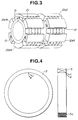
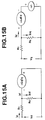
- Figs. 1 to 4 show a structure of a hybrid excitation type permanent magnet synchronous motor whose control is realized by a method and control system according to the present invention.
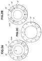
- the armature coil 3 is disposed so as to cross the N-pole and S-pole cores 2a and 2b.
- the excitation coil 5 is formed by winding a wire 5a and treating it by the insulation process. The number of turns of the excitation coil 5 is adjusted so as to generate a necessary magnetmotive force upon matching with a capacity of the electric source and the machinery dimension.
- a rotor 11 is constituted by a rotor core 12 and a plurality of permanent magnets (PM) 13.
- the rotor core 12 is fixedly supported to a yoke 14 connected to a shaft 15.
- the rotor core 12 has salient pole portions 12a which project form the rotor core 12 and function as a salient pole, and the salient pole portions 12a are disposed at portions where the permanent magnets 13 are not located.
- the permanent magnet 13 is embedded in the rotor 11 and covered with the rotor core 12.
- a slit 20 is formed between each permanent magnet 13 and each pole salient portion 12a in relation that the permanent magnets 13 and the salient pole portions 12a are fixed on the yoke.
- non-magnetic reinforcement plates 21 are disposed in the several portions in the axial direction.
- the non-magnetic reinforcement plates 21, the salient pole portions 12a and the rotor cores 12 are integrally fitted with each other by inserting aluminum-alloy die-cast member or copper bar to slots 22.
- the inserted member and a pair of end rings installed at an axial end form an electric current passage.
- the salient pole portions 12a are divided into N-pole salient pole portions 12aN and S-pole salient pole portions 12aS which are dividedly disposed so as to be opposite to the N-pole and S-pole cores 2a and 2b, respectively.
- the permanent magnets 13 are fixedly attached on the rotor core 12, and the rotor core 12 is inserted into the yoke 12 to be supported thereby.
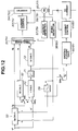
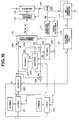
- FIGs. 6 to 35 there are shown embodiments of a control system of the above-mentioned motor, according to the present invention.
- a rotation speed of the motor 35 is controlled by the inverter 34 and detected by a rotation speed detector 35.
- the detected signal by the rotation speed detector 35 is inputted as a rotational position to the three-phase current calculator 32 through a position detecting circuit 37.
- the detected signal by the rotation speed detector 36 is modulated as a present speed in a speed detecting circuit 38 and is then added to the speed command ⁇ *.
- the modulated signal at the speed detecting circuit 38 is transformed into a field-magnet magnetic flux ⁇ at an calculator 39.
- An excitation current calculator 40 obtains an electric current i f from the field magnetic-flux, and a DC electric current control circuit 41 is controlled according to the obtained electric current i f .
- Fig. 5 If the control system of Fig. 5 is used as a torque control, the left hand side part divided by a broken line of Fig. 5 is not necessary in such a torque control system.
- the equation (5) is applied only for a low-speed and/or low-load operation.
- the voltage of the motor terminal is obtained from the equation (5) as follows: When a possible output voltage of the inverter is V max , the motor is operable within the range in that V ⁇ V max . That is, the operable range of the motor is under a condition V ⁇ V max .
- Fig. 6 shows such examination data which indicates that the torque T is largely varied according to the value K.
- the torque T is determined from the valve K and the primary current, it is preferable to set K ⁇ 0 in a K value constant control in order to obtain a high-torque relative by the small electric current.
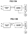
- Fig. 9 shows a speed control circuit to which a speed command ⁇ * is inputted.
- the speed control circuit is generally similar to the torque control circuit of Fig. 9 except that a torque calculator 62 for calculating a torque command T* from the speed command ⁇ * is provided in front of the I q calculator 50 and a feed back command from a speed detecting section 58 is added to the speed command ⁇ *.
- I q V max / ⁇ L q (12)
- I d V max / ⁇ L q (12)
- I d V max / ⁇ L q (12)
- the motor control system it is possible to extend the operable range of the PM motor which includes a DC field magnet coil. Furthermore, it is possible to form the motor more smaller and to improve the efficiency due to the increase of the maximum torque and the raising of the maximum rotation speed. This further enables the current capacity of the electric source to be smaller.
- the control method is a method for deciding the current ratio and the magnetic flux by taking account the iron loss and using previously prepared a current ration (k) table and a magnet flux ( ⁇ ) table.
- Fig. 15A and 15B show the equivalent circuits of this control system, in which the respective circuits of the q-axis and d-axis are described and where V d is a d-axis component of an armature voltage, V q is q-axis component of an armature voltage of the q-axis, I d is a d-axis component of an armature current, I q is a q-axis component of an armature current, R1 is a resistance of the armature, R c is an equivalent iron-loss resistance, L d is a d-axis inductance, L q is a q-axis inductance, ⁇ is an angle frequency of an electric source, ⁇ is an interlinkage magnetic flux of the armature coil, I cd and I cq are current iron losses, and I d ' and I q ' are current loading.
- the q-axis current component I q ' is obtained from k*, the torque command T* and the magnetic flux ⁇ *.
- a multiplier 104 a d-axis current component is obtained by multiplying the current I q ' and k*.
- an adder 106 an output I q is obtained by adding I q ' and I cq (I q ' + I cq ).
- an iron loss current I cd is obtained by substituting the q-axis current component I q ' and the equivalent iron loss R c into the equation (26).
- the control output of the inverter 113 is obtained from the three-phase current values i u , i v and i w .
- a rotation speed detector PS of the motor 114 is connected to a position detecting circuit 111 for obtaining the output Q and a speed detecting circuit 115.
- the speed detecting circuit 115 output ⁇ which is send to the k calculating circuit 101, the ⁇ calculating circuit 102 and the R c calculating circuit 108.
- the exciting current calculating circuit 116 receives an output ⁇ from the ⁇ calculating circuit and outputs i f * to the DC current control circuit 117.
- step S10 When the judgement in the step S10 is "NO”, the program proceeds to a step S11 wherein it is judged whether T is smaller than T max or not.
- the program proceeds to a step S12 wherein it is judged whether ⁇ r is smaller than ⁇ r max or not.
- the program proceeds to END.
- a feedback of I d ' and I q ' may be implemented for the control of V d and V q .
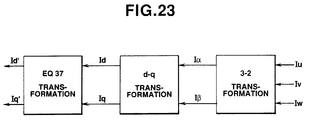
- a feedback of I d and I q is implemented from the output V u and V w of the PWM inverter, in order to obtain I d ' and I q ' from which iron-loss current has already eliminated, it is necessary to implement further transformation.
- Fig. 23 shows a feedback system of a modulation of a feedback system shown by a hatching in Fig. 21 upon taking into consideration with the equation (37). That is, d'-q' transformation represented by the equation (37) is implemented after the 3 ⁇ -2 ⁇ transformation and the d-q transformation.
- An area enclosed by a broken line shows a non-interference IP control system which eliminates iron-loss.
- a disturbance which can not be controlled independently in d-axis and q-axis, that is, an interference term, is K r ( ⁇ m + M f I f ) at the d-axis which is of an induced voltage due to the q-axis inductance and the d-axis inductance. and ⁇ kL d I q ' and ⁇ Kr( ⁇ m + M f I f ) at the q-axis which is of an induced voltage generated by the change of the magnetic flux by the DC field magnet current of q-axis.
- a feed-forward compensation is implemented relative to d-axis and q-axis as a control for eliminating the disturbance. That is, a feed-forward compensation of ⁇ (L d I q + ⁇ ) shown in Fig. 21 is implemented.
- Figs. 24 and 25 show an example of a non-interference processing by a feed-forward compensation, which is of a proportion-integral (PI) control system.
- a current control section between the table command and ⁇ - ⁇ transformation includes a proportion integral element K pd (1+1/ST Id ) ⁇ K pd (1 + 1/ST Iq ) , and feed-forward compensation elements ⁇ K r L d , ⁇ K ⁇ K q and ⁇ K r ( ⁇ m +M f I f ).
- Command values I d * and I q *, and feedback values I d ' and I q ' are inputted thereto and the command values V d * and V q * are outputted therefrom upon eliminating the disturbance. Accordingly, with this non-interference processing, d-axis and q-axis are independently separated as shown in Fig. 25, and therefore the performance of the control is improved.
- Figs. 26 and 27 show another embodiment of the non-interference processing of a IP control system.
- the structure of the IP control system of Fig. 26 is the same as that of the current control section shown in Fig. 21.
- the IP control system incudes a proportion elements K pd and K pq and feed-forward compensations ⁇ k r L d , ⁇ K r L q and ⁇ K r ( ⁇ m +M f I f ) in addition to integral elements K Id /S and K Iq /S. Accordingly, the control system of Fig. 26 also suppresses the disturbance.
- the non-interference processing shown in Fig. 27 it becomes possible to separate d-axis and q-axis, and therefore the control performance is improved.
- Figs. 24 and 25 show the PI control system which is implemented by using "primary delay” and Fig. 26 and 27 show IP control system which implemented by using "secondary delay”. That is, in PI control the difference between the command value and the feedback value is inputted to both the integral term and the proportion term, and V d * and V q * are outputted so as to decrease the difference to 0.
- V d * and V q * are outputted so as to decrease the difference to 0.
- the current values I d ', I q ' and I f of the interference term may be exchanged by the command I d *, I q * and I f *. That is, ⁇ K r L d I d ' to ⁇ K r L d I d '*, ⁇ K r L q I q ' to ⁇ K r L q I q '*, and ⁇ K r ( ⁇ m + M f I f ) to ⁇ K r ( ⁇ m +M f I f *).
- I f * is a DC exiting current command.
- Fig. 30 shows a PI control system by which non-interference processing is implemented.
- Fig. 31 shows a IP control system.
- the difference between Fig. 24 and Fig. 26 is that a coefficient relating to the iron loss is omitted.
- the embodiments in Figs. 30 and 31 are equivalent with embodiments that I d '*, I q '*, I d ' and I q ' are replaced with I d *, I q *, I d and I q , respectively in the embodiments of Figs. 25 and 27.
- the response characteristics of Figs. 30 and 31 are equivalent with the equations (38) and (39).
- I d , I q and I f of the interference term may be replaced with I d *, I q * and I f *, respectively.
Applications Claiming Priority (9)
| Application Number | Priority Date | Filing Date | Title |
|---|---|---|---|
| JP11562993 | 1993-05-18 | ||
| JP11562993 | 1993-05-18 | ||
| JP115629/93 | 1993-05-18 | ||
| JP9469/94 | 1994-01-31 | ||
| JP946994 | 1994-01-31 | ||
| JP946994 | 1994-01-31 | ||
| JP07504994A JP3331734B2 (ja) | 1993-05-18 | 1994-04-13 | 回転電機の制御方式 |
| JP75049/94 | 1994-04-13 | ||
| JP7504994 | 1994-04-13 |
Publications (3)
| Publication Number | Publication Date |
|---|---|
| EP0631373A2 true EP0631373A2 (de) | 1994-12-28 |
| EP0631373A3 EP0631373A3 (de) | 1996-07-17 |
| EP0631373B1 EP0631373B1 (de) | 2000-08-30 |
Family
ID=27278491
Family Applications (1)
| Application Number | Title | Priority Date | Filing Date |
|---|---|---|---|
| EP94107624A Expired - Lifetime EP0631373B1 (de) | 1993-05-18 | 1994-05-17 | Verfahren und Vorrichtung zur Steuerung eines Synchronousmotors mit permanenten Magneten und Hybriderregung |
Country Status (6)
| Country | Link |
|---|---|
| US (1) | US5689166A (de) |
| EP (1) | EP0631373B1 (de) |
| JP (1) | JP3331734B2 (de) |
| KR (1) | KR940027285A (de) |
| DE (1) | DE69425704T2 (de) |
| TW (1) | TW260839B (de) |
Cited By (7)
| Publication number | Priority date | Publication date | Assignee | Title |
|---|---|---|---|---|
| FR2867324A1 (fr) * | 2004-03-08 | 2005-09-09 | Mitsubishi Electric Corp | Dispositif de commande de machine synchrone a champs enroules |
| US8120222B2 (en) | 2008-07-16 | 2012-02-21 | Cummins Generator Technologies Limited | Rotating electrical machine |
| WO2012131269A2 (fr) * | 2011-03-30 | 2012-10-04 | Renault S.A.S. | Systeme et procede de commande d'un moteur electrique a phases multiples prenant en compte les oscillations de courant |
| FR2978888A3 (fr) * | 2011-08-04 | 2013-02-08 | Renault Sa | Systeme et procede de commande d'une machine electrique a rejection d'harmoniques. |
| WO2013060996A1 (fr) * | 2011-10-28 | 2013-05-02 | Valeo Equipements Electriques Moteur | Procede de pilotage d'une machine electrique tournante synchrone a double excitation et machine electrique tournante correspondante |
| DE112013000536B4 (de) * | 2012-02-29 | 2015-10-22 | Aisin Aw Co., Ltd. | Drehende Elektromaschine mit Hybriderregung |
| WO2018080996A1 (en) * | 2016-10-25 | 2018-05-03 | Microchip Technology Incorporated | Closed loop flux weakening for permanent magent synchronous motors |
Families Citing this family (33)
| Publication number | Priority date | Publication date | Assignee | Title |
|---|---|---|---|---|
| US6163128A (en) * | 1999-08-20 | 2000-12-19 | General Motors Corporation | Method and drive system for controlling a permanent magnet synchronous machine |
| KR100331336B1 (ko) | 1999-09-07 | 2002-04-01 | 윤종용 | Dc 스핀들 모터 속도 검출장치 및 방법 |
| JP4556322B2 (ja) * | 2000-11-17 | 2010-10-06 | シンフォニアテクノロジー株式会社 | モータ制御方式 |
| US6573745B2 (en) | 2001-05-04 | 2003-06-03 | Ford Global Technologies, Inc. | Permanent magnet degradation monitoring for hybrid and electric vehicles |
| US6407521B1 (en) | 2001-09-17 | 2002-06-18 | Ford Global Technologies, Inc. | Adaptive demagnetization compensation for a motor in an electric or partially electric motor vehicle |
| US6427794B1 (en) | 2001-09-17 | 2002-08-06 | Ford Global Technologies, Inc. | Adaptive demagnetization compensation for a motor in an electric or partially electric motor vehicle |
| US6720792B2 (en) | 2001-09-17 | 2004-04-13 | Ford Global Technologies, Llc | Detection of demagnetization in a motor in an electric or partially electric motor vehicle |
| US6936991B2 (en) * | 2002-06-03 | 2005-08-30 | Ballard Power Systems Corporation | Method and apparatus for motor control |
| JP2005045879A (ja) * | 2003-07-24 | 2005-02-17 | Toyota Motor Corp | 動力出力装置およびモータの駆動制御をコンピュータに実行させるためのプログラムを記録したコンピュータ読取り可能な記録媒体 |
| US7230998B2 (en) * | 2003-11-26 | 2007-06-12 | Delphi Technologies, Inc. | Method to increase performance of secondary data in a hierarchical modulation scheme |
| JPWO2005093942A1 (ja) * | 2004-03-24 | 2007-08-30 | 三菱電機株式会社 | 永久磁石式同期モータの制御装置 |
| KR100598809B1 (ko) * | 2004-07-06 | 2006-07-10 | 현대자동차주식회사 | 환경 차량의 전동기 제어방법 |
| JP2006191721A (ja) * | 2005-01-05 | 2006-07-20 | Yaskawa Electric Corp | モータ制御装置とその制御方法 |
| WO2007007387A1 (ja) | 2005-07-11 | 2007-01-18 | Hitachi, Ltd. | 界磁巻線型同期モータの制御装置,電動駆動システム,電動4輪駆動車およびハイブリッド自動車 |
| US7586286B2 (en) * | 2006-11-17 | 2009-09-08 | Continental Automotive Systems Us, Inc. | Method and apparatus for motor control |
| JP5134846B2 (ja) * | 2007-03-26 | 2013-01-30 | 株式会社東芝 | 永久磁石電動機ドライブシステム |
| JP4834712B2 (ja) * | 2008-10-15 | 2011-12-14 | 株式会社東芝 | モータ制御装置,モータ制御システム,洗濯機及び永久磁石モータの着磁方法 |
| WO2010098006A1 (ja) | 2009-02-24 | 2010-09-02 | 有限会社クラ技術研究所 | 磁束量可変回転電機システム |
| JP5857799B2 (ja) * | 2012-02-29 | 2016-02-10 | アイシン・エィ・ダブリュ株式会社 | ハイブリッド励磁式回転電機 |
| JP5633551B2 (ja) * | 2012-11-05 | 2014-12-03 | 株式会社安川電機 | 交流電動機の制御装置 |
| JP5620526B2 (ja) * | 2013-02-05 | 2014-11-05 | 山洋電気株式会社 | モータ制御装置 |
| CN103715961B (zh) * | 2013-12-19 | 2016-02-03 | 华中科技大学 | 基于模型预测的双凸极永磁同步电机直接转矩控制方法 |
| KR101646467B1 (ko) * | 2015-06-18 | 2016-08-05 | 현대자동차주식회사 | 친환경자동차의 모터 감자 진단 방법 |
| US9995119B2 (en) | 2015-11-16 | 2018-06-12 | Ge Oil & Gas Esp, Inc. | Electric submersible pumping system with permanent magnet motor |
| WO2018139331A1 (ja) * | 2017-01-24 | 2018-08-02 | 株式会社日立産機システム | モータ電力変換装置、及び、それを用いたモータ電力変換システム |
| JP6971439B2 (ja) * | 2017-06-15 | 2021-11-24 | 有限会社シー・アンド・エス国際研究所 | 二重三相巻線永久磁石同期形電動機の数学モデルと同モデルに立脚した模擬・特性解析・制御装置 |
| CN108923703B (zh) * | 2018-07-25 | 2021-07-20 | 江苏大学 | 一种基于损耗调节的高效率区移动方法 |
| TWI713988B (zh) * | 2019-02-01 | 2020-12-21 | 台灣日立江森自控股份有限公司 | 用於空調設備之馬達控制裝置及其馬達控制方法 |
| CN109818541B (zh) * | 2019-03-13 | 2020-10-02 | 东南大学 | 一种用于磁链观测的记忆电机绕组复用控制方法及系统 |
| CN111740664B (zh) * | 2020-07-06 | 2023-07-25 | 东风电子科技股份有限公司 | 实现基于Id=0的凸极永磁同步电机弱磁控制的方法 |
| CN113517835B (zh) * | 2021-04-22 | 2023-06-06 | 湖南工业大学 | Pmsm驱动系统失磁故障控制方法、永磁同步电机 |
| CN115940731A (zh) * | 2022-07-26 | 2023-04-07 | 小米汽车科技有限公司 | 电机效率优化方法、装置、车辆及可读存储介质 |
| CN116620042B (zh) * | 2023-06-05 | 2024-02-06 | 小米汽车科技有限公司 | 电机控制参数标定方法、装置及车辆 |
Citations (7)
| Publication number | Priority date | Publication date | Assignee | Title |
|---|---|---|---|---|
| DE1563709A1 (de) * | 1966-05-21 | 1970-02-19 | Siemens Ag | Drehzahlregeleinrichtung fuer Gleichstromnebenschlussmotoren |
| EP0085871A1 (de) * | 1982-02-05 | 1983-08-17 | Siemens Aktiengesellschaft | Verfahren zur Erhöhung der Maximaldrehzahl einer Synchronmaschine bei vorgegebener Erregerfeldstärke und Klemmenspannung und Schaltungsanordnung zur Durchführung des Verfahrens |
| EP0167158A2 (de) * | 1984-07-03 | 1986-01-08 | Volker Dipl.-Ing. Fleckenstein | Drehzahlgeregelte elektrische Antriebsvorrichtung mit Feldschwächbereich |
| DE3426326A1 (de) * | 1984-07-17 | 1986-01-30 | Siemens AG, 1000 Berlin und 8000 München | Verfahren zum betrieb einer umrichtergespeisten synchronmaschine |
| DE3045575C2 (de) * | 1980-11-29 | 1986-10-09 | Licentia Patent-Verwaltungs-Gmbh, 6000 Frankfurt | Verfahren zur Steuerung und Regelung einer direktumrichtergespeisten Synchronmaschine |
| EP0201872A2 (de) * | 1985-05-13 | 1986-11-20 | General Electric Company | Flussschwächungsbetrieb eines inneren Permanentmagnetsynchronmotors |
| EP0325982A1 (de) * | 1988-01-29 | 1989-08-02 | Siemens Aktiengesellschaft | Verfahren zur Bildung des Lastwinkel-Istwerts für eine feldorientiert geregelte Drehfeldmaschine und entsprechende Regelung |
Family Cites Families (14)
| Publication number | Priority date | Publication date | Assignee | Title |
|---|---|---|---|---|
| JPS5291115A (en) * | 1976-01-28 | 1977-08-01 | Mitsubishi Electric Corp | Control apparatus for synchronous machine |
| US4088934A (en) * | 1976-10-04 | 1978-05-09 | General Electric Company | Means for stabilizing an a-c electric motor drive system |
| US4358722A (en) * | 1977-08-17 | 1982-11-09 | Kabushiki Kaisha Yaskawa Denki Seisakusho | Speed detector using resolver |
| US4368411A (en) * | 1981-07-13 | 1983-01-11 | Kollmorgen Technologies Corporation | Control system for electric motor |
| JPS58123394A (ja) * | 1982-01-18 | 1983-07-22 | Hitachi Ltd | 交流電動機の制御装置 |
| US4631657A (en) * | 1982-09-29 | 1986-12-23 | Microbot, Inc. | Control and force-sensing method and apparatus for motors |
| US4460861A (en) * | 1983-01-21 | 1984-07-17 | Westinghouse Electric Corp. | Control system for machine commutated inverter-synchronous motor drives |
| US4527109A (en) * | 1983-02-22 | 1985-07-02 | Mitsubishi Denki Kabushiki Kaisha | Control apparatus for thyristor motor |
| JPH063994B2 (ja) * | 1984-10-05 | 1994-01-12 | 株式会社日立製作所 | 複数台デイジタルサーボの制御方法 |
| FR2597228B1 (fr) * | 1986-04-10 | 1988-07-22 | Electricite De France | Procede et dispositif de simulation d'une machine electrique synchrone |
| US4884016A (en) * | 1988-08-23 | 1989-11-28 | Aerotech, Inc. | Closed loop torque angle control of synchronous motor |
| JPH02219498A (ja) * | 1989-02-16 | 1990-09-03 | Toyota Central Res & Dev Lab Inc | インバータの電流制御装置 |
| US5034668A (en) * | 1989-12-04 | 1991-07-23 | Synektron Corporation | Control circuit for an electric motor |
| JP3164580B2 (ja) * | 1990-09-27 | 2001-05-08 | 豊田工機株式会社 | ディジタルサーボ制御装置 |
-
1994
- 1994-04-13 JP JP07504994A patent/JP3331734B2/ja not_active Expired - Lifetime
- 1994-05-17 KR KR1019940010866A patent/KR940027285A/ko active Search and Examination
- 1994-05-17 DE DE69425704T patent/DE69425704T2/de not_active Expired - Fee Related
- 1994-05-17 EP EP94107624A patent/EP0631373B1/de not_active Expired - Lifetime
- 1994-05-23 TW TW083104648A patent/TW260839B/zh active
-
1996
- 1996-05-13 US US08/647,263 patent/US5689166A/en not_active Expired - Lifetime
Patent Citations (7)
| Publication number | Priority date | Publication date | Assignee | Title |
|---|---|---|---|---|
| DE1563709A1 (de) * | 1966-05-21 | 1970-02-19 | Siemens Ag | Drehzahlregeleinrichtung fuer Gleichstromnebenschlussmotoren |
| DE3045575C2 (de) * | 1980-11-29 | 1986-10-09 | Licentia Patent-Verwaltungs-Gmbh, 6000 Frankfurt | Verfahren zur Steuerung und Regelung einer direktumrichtergespeisten Synchronmaschine |
| EP0085871A1 (de) * | 1982-02-05 | 1983-08-17 | Siemens Aktiengesellschaft | Verfahren zur Erhöhung der Maximaldrehzahl einer Synchronmaschine bei vorgegebener Erregerfeldstärke und Klemmenspannung und Schaltungsanordnung zur Durchführung des Verfahrens |
| EP0167158A2 (de) * | 1984-07-03 | 1986-01-08 | Volker Dipl.-Ing. Fleckenstein | Drehzahlgeregelte elektrische Antriebsvorrichtung mit Feldschwächbereich |
| DE3426326A1 (de) * | 1984-07-17 | 1986-01-30 | Siemens AG, 1000 Berlin und 8000 München | Verfahren zum betrieb einer umrichtergespeisten synchronmaschine |
| EP0201872A2 (de) * | 1985-05-13 | 1986-11-20 | General Electric Company | Flussschwächungsbetrieb eines inneren Permanentmagnetsynchronmotors |
| EP0325982A1 (de) * | 1988-01-29 | 1989-08-02 | Siemens Aktiengesellschaft | Verfahren zur Bildung des Lastwinkel-Istwerts für eine feldorientiert geregelte Drehfeldmaschine und entsprechende Regelung |
Non-Patent Citations (2)
| Title |
|---|
| CONF. RECORD OF THE 1986 IEEE, 28 October 1986, DENVER, USA, pages 814-823, XP000195912 T.M.JAHNS: "Flux-weakening regime operation of an interior permanent magnet synchronous motor drive " * |
| IEEE TRANSACTIONS ON INDUSTRIAL ELECTRONICS , vol. 33, no. 1, February 1986, N.Y. USA, pages 87-91, XP002001643 S.OGASAWARA & AL.: "A high performance ac servo system with permanent magnet synchronous motors" * |
Cited By (13)
| Publication number | Priority date | Publication date | Assignee | Title |
|---|---|---|---|---|
| FR2867324A1 (fr) * | 2004-03-08 | 2005-09-09 | Mitsubishi Electric Corp | Dispositif de commande de machine synchrone a champs enroules |
| US8120222B2 (en) | 2008-07-16 | 2012-02-21 | Cummins Generator Technologies Limited | Rotating electrical machine |
| WO2012131269A3 (fr) * | 2011-03-30 | 2013-07-18 | Renault S.A.S. | Systeme et procede de commande d'un moteur electrique a phases multiples prenant en compte les oscillations de courant |
| WO2012131269A2 (fr) * | 2011-03-30 | 2012-10-04 | Renault S.A.S. | Systeme et procede de commande d'un moteur electrique a phases multiples prenant en compte les oscillations de courant |
| FR2973607A1 (fr) * | 2011-03-30 | 2012-10-05 | Renault Sa | Systeme et procede de commande d'un moteur electrique a phases multiples prenant en compte les oscillations de courant. |
| US9960720B2 (en) | 2011-03-30 | 2018-05-01 | Renault S.A.S. | System and method for controlling a multiphase electric motor while taking current oscillations into account |
| FR2978888A3 (fr) * | 2011-08-04 | 2013-02-08 | Renault Sa | Systeme et procede de commande d'une machine electrique a rejection d'harmoniques. |
| FR2982097A1 (fr) * | 2011-10-28 | 2013-05-03 | Valeo Equip Electr Moteur | Procede de pilotage d'une machine electrique tournante synchrone a double excitation et machine electrique tournante correspondante |
| WO2013060996A1 (fr) * | 2011-10-28 | 2013-05-02 | Valeo Equipements Electriques Moteur | Procede de pilotage d'une machine electrique tournante synchrone a double excitation et machine electrique tournante correspondante |
| DE112013000536B4 (de) * | 2012-02-29 | 2015-10-22 | Aisin Aw Co., Ltd. | Drehende Elektromaschine mit Hybriderregung |
| US9806569B2 (en) | 2012-02-29 | 2017-10-31 | Aisin Aw Co., Ltd. | Hybrid excitation rotating electrical machine |
| WO2018080996A1 (en) * | 2016-10-25 | 2018-05-03 | Microchip Technology Incorporated | Closed loop flux weakening for permanent magent synchronous motors |
| US10008967B2 (en) | 2016-10-25 | 2018-06-26 | Microchip Technology Inc. | Closed loop flux weakening for permanent magnet synchronous motors |
Also Published As
| Publication number | Publication date |
|---|---|
| KR940027285A (ko) | 1994-12-10 |
| DE69425704D1 (de) | 2000-10-05 |
| DE69425704T2 (de) | 2001-04-12 |
| EP0631373A3 (de) | 1996-07-17 |
| EP0631373B1 (de) | 2000-08-30 |
| JP3331734B2 (ja) | 2002-10-07 |
| TW260839B (de) | 1995-10-21 |
| US5689166A (en) | 1997-11-18 |
| JPH07322673A (ja) | 1995-12-08 |
Similar Documents
| Publication | Publication Date | Title |
|---|---|---|
| EP0631373A2 (de) | Verfahren und Vorrichtung zur Steuerung eines Synchronousmotors mit permanenten Magneten und Hybriderregung | |
| Mademlis et al. | Optimal efficiency control strategy for interior permanent-magnet synchronous motor drives | |
| Bianchi et al. | Parameters and volt-ampere ratings of a synchronous motor drive for flux-weakening applications | |
| Lu et al. | A review of flux-weakening control in permanent magnet synchronous machines | |
| Mademlis et al. | On considering magnetic saturation with maximum torque to current control in interior permanent magnet synchronous motor drives | |
| US20060132082A1 (en) | Method and system for controlling permanent magnet synchronous motor | |
| Yamamoto et al. | Universal sensorless vector control of induction and permanent-magnet synchronous motors considering equivalent iron loss resistance | |
| Kronberg | Design and simulation of field oriented control and direct torque control for a permanent magnet synchronous motor with positive saliency | |
| Ding et al. | Maximum ratio of torque to copper loss control for hybrid excited flux-switching machine in whole speed range | |
| Bonisławski et al. | Unconventional control system of hybrid excited synchronous machine | |
| Zhu et al. | Investigation of voltage distortion in fractional slot interior permanent magnet machines having different slot and pole number combinations | |
| Mbayed et al. | Hybrid excitation synchronous motor control in electric vehicle with copper and iron losses minimization | |
| Morimoto et al. | Effects and compensation of magnetic saturation in permanent magnet synchronous motor drives | |
| Akhil et al. | Modified flux-weakening control for electric vehicle with PMSM drive | |
| Kashif et al. | Solar PV-fed reverse saliency spoke-type PMSM with hybrid ANF-based self-sensing for water pump system | |
| Yoon et al. | New flux weakening control for high saliency interior permanent magnet synchronous machine without any tables | |
| Ogbuka et al. | A fast hysteresis current–controlled permanent magnet synchronous motor drive based on field orientation | |
| Usama et al. | Simplified model predicted current control method for speed control of non-silent permanent magnet synchronous motors | |
| Pothi et al. | A new control strategy for hybrid-excited switched-flux permanent magnet machines without the requirement of machine parameters | |
| Zaghrini et al. | Minimum copper losses per torque optimization on electrically excited synchronous motors for electric vehicles applications | |
| Guan et al. | Calculation of torque-speed characteristic of induction machine for electrical vehicle application using analytical method | |
| Morimoto et al. | Variable speed drive system of interior permanent magnet synchronous motors for constant power operation | |
| Haque et al. | Improved trajectory control for an interior permanent magnet synchronous motor drive with extended operating limit | |
| Marques et al. | Minimum loss conditions in a salient-pole wound-field synchronous machine drive | |
| US4958116A (en) | Method for controlling AC induction motor |
Legal Events
| Date | Code | Title | Description |
|---|---|---|---|
| PUAI | Public reference made under article 153(3) epc to a published international application that has entered the european phase |
Free format text: ORIGINAL CODE: 0009012 |
|
| 17P | Request for examination filed |
Effective date: 19940517 |
|
| AK | Designated contracting states |
Kind code of ref document: A2 Designated state(s): DE FR GB IT SE |
|
| PUAL | Search report despatched |
Free format text: ORIGINAL CODE: 0009013 |
|
| PUAF | Information related to the publication of a search report (a3 document) modified or deleted |
Free format text: ORIGINAL CODE: 0009199SEPU |
|
| AK | Designated contracting states |
Kind code of ref document: A3 Designated state(s): DE FR GB IT SE |
|
| D17D | Deferred search report published (deleted) | ||
| PUAL | Search report despatched |
Free format text: ORIGINAL CODE: 0009013 |
|
| AK | Designated contracting states |
Kind code of ref document: A3 Designated state(s): DE FR GB IT SE |
|
| 17Q | First examination report despatched |
Effective date: 19961024 |
|
| GRAG | Despatch of communication of intention to grant |
Free format text: ORIGINAL CODE: EPIDOS AGRA |
|
| GRAG | Despatch of communication of intention to grant |
Free format text: ORIGINAL CODE: EPIDOS AGRA |
|
| GRAH | Despatch of communication of intention to grant a patent |
Free format text: ORIGINAL CODE: EPIDOS IGRA |
|
| GRAH | Despatch of communication of intention to grant a patent |
Free format text: ORIGINAL CODE: EPIDOS IGRA |
|
| GRAA | (expected) grant |
Free format text: ORIGINAL CODE: 0009210 |
|
| AK | Designated contracting states |
Kind code of ref document: B1 Designated state(s): DE FR GB IT SE |
|
| REF | Corresponds to: |
Ref document number: 69425704 Country of ref document: DE Date of ref document: 20001005 |
|
| ITF | It: translation for a ep patent filed |
Owner name: BUGNION S.P.A. |
|
| ET | Fr: translation filed | ||
| PLBE | No opposition filed within time limit |
Free format text: ORIGINAL CODE: 0009261 |
|
| STAA | Information on the status of an ep patent application or granted ep patent |
Free format text: STATUS: NO OPPOSITION FILED WITHIN TIME LIMIT |
|
| 26N | No opposition filed | ||
| REG | Reference to a national code |
Ref country code: GB Ref legal event code: IF02 |
|
| PGFP | Annual fee paid to national office [announced via postgrant information from national office to epo] |
Ref country code: GB Payment date: 20020423 Year of fee payment: 9 |
|
| PGFP | Annual fee paid to national office [announced via postgrant information from national office to epo] |
Ref country code: FR Payment date: 20020517 Year of fee payment: 9 |
|
| PGFP | Annual fee paid to national office [announced via postgrant information from national office to epo] |
Ref country code: SE Payment date: 20020524 Year of fee payment: 9 |
|
| PGFP | Annual fee paid to national office [announced via postgrant information from national office to epo] |
Ref country code: DE Payment date: 20020625 Year of fee payment: 9 |
|
| PG25 | Lapsed in a contracting state [announced via postgrant information from national office to epo] |
Ref country code: GB Free format text: LAPSE BECAUSE OF NON-PAYMENT OF DUE FEES Effective date: 20030517 |
|
| PG25 | Lapsed in a contracting state [announced via postgrant information from national office to epo] |
Ref country code: SE Free format text: LAPSE BECAUSE OF NON-PAYMENT OF DUE FEES Effective date: 20030518 |
|
| PG25 | Lapsed in a contracting state [announced via postgrant information from national office to epo] |
Ref country code: DE Free format text: LAPSE BECAUSE OF NON-PAYMENT OF DUE FEES Effective date: 20031202 |
|
| EUG | Se: european patent has lapsed | ||
| GBPC | Gb: european patent ceased through non-payment of renewal fee |
Effective date: 20030517 |
|
| PG25 | Lapsed in a contracting state [announced via postgrant information from national office to epo] |
Ref country code: FR Free format text: LAPSE BECAUSE OF NON-PAYMENT OF DUE FEES Effective date: 20040130 |
|
| REG | Reference to a national code |
Ref country code: FR Ref legal event code: ST |
|
| PG25 | Lapsed in a contracting state [announced via postgrant information from national office to epo] |
Ref country code: IT Free format text: LAPSE BECAUSE OF NON-PAYMENT OF DUE FEES;WARNING: LAPSES OF ITALIAN PATENTS WITH EFFECTIVE DATE BEFORE 2007 MAY HAVE OCCURRED AT ANY TIME BEFORE 2007. THE CORRECT EFFECTIVE DATE MAY BE DIFFERENT FROM THE ONE RECORDED. Effective date: 20050517 |