EP0631373A2 - Method and apparatus for controlling hybrid excitation type permanent magnet synchronous motor - Google Patents
Method and apparatus for controlling hybrid excitation type permanent magnet synchronous motor Download PDFInfo
- Publication number
- EP0631373A2 EP0631373A2 EP94107624A EP94107624A EP0631373A2 EP 0631373 A2 EP0631373 A2 EP 0631373A2 EP 94107624 A EP94107624 A EP 94107624A EP 94107624 A EP94107624 A EP 94107624A EP 0631373 A2 EP0631373 A2 EP 0631373A2
- Authority
- EP
- European Patent Office
- Prior art keywords
- current
- motor
- axis component
- component
- direct
- Prior art date
- Legal status (The legal status is an assumption and is not a legal conclusion. Google has not performed a legal analysis and makes no representation as to the accuracy of the status listed.)
- Granted
Links
Images


Classifications
-
- H—ELECTRICITY
- H02—GENERATION; CONVERSION OR DISTRIBUTION OF ELECTRIC POWER
- H02P—CONTROL OR REGULATION OF ELECTRIC MOTORS, ELECTRIC GENERATORS OR DYNAMO-ELECTRIC CONVERTERS; CONTROLLING TRANSFORMERS, REACTORS OR CHOKE COILS
- H02P21/00—Arrangements or methods for the control of electric machines by vector control, e.g. by control of field orientation
- H02P21/06—Rotor flux based control involving the use of rotor position or rotor speed sensors
-
- H—ELECTRICITY
- H02—GENERATION; CONVERSION OR DISTRIBUTION OF ELECTRIC POWER
- H02K—DYNAMO-ELECTRIC MACHINES
- H02K21/00—Synchronous motors having permanent magnets; Synchronous generators having permanent magnets
- H02K21/02—Details
- H02K21/04—Windings on magnets for additional excitation ; Windings and magnets for additional excitation
- H02K21/046—Windings on magnets for additional excitation ; Windings and magnets for additional excitation with rotating permanent magnets and stationary field winding
-
- H—ELECTRICITY
- H02—GENERATION; CONVERSION OR DISTRIBUTION OF ELECTRIC POWER
- H02P—CONTROL OR REGULATION OF ELECTRIC MOTORS, ELECTRIC GENERATORS OR DYNAMO-ELECTRIC CONVERTERS; CONTROLLING TRANSFORMERS, REACTORS OR CHOKE COILS
- H02P21/00—Arrangements or methods for the control of electric machines by vector control, e.g. by control of field orientation
- H02P21/0085—Arrangements or methods for the control of electric machines by vector control, e.g. by control of field orientation specially adapted for high speeds, e.g. above nominal speed
- H02P21/0089—Arrangements or methods for the control of electric machines by vector control, e.g. by control of field orientation specially adapted for high speeds, e.g. above nominal speed using field weakening
-
- H—ELECTRICITY
- H02—GENERATION; CONVERSION OR DISTRIBUTION OF ELECTRIC POWER
- H02P—CONTROL OR REGULATION OF ELECTRIC MOTORS, ELECTRIC GENERATORS OR DYNAMO-ELECTRIC CONVERTERS; CONTROLLING TRANSFORMERS, REACTORS OR CHOKE COILS
- H02P25/00—Arrangements or methods for the control of AC motors characterised by the kind of AC motor or by structural details
- H02P25/02—Arrangements or methods for the control of AC motors characterised by the kind of AC motor or by structural details characterised by the kind of motor
- H02P25/022—Synchronous motors
- H02P25/03—Synchronous motors with brushless excitation
Definitions
- the present invention relates to method and apparatus for controlling a hybrid excitation type permanent magnet synchronous motor.
- the method includes the steps of: controlling the magnetic flux of the field so as to keep constant when a rotation speed of the motor is smaller than a predetermined base speed and so as to change in reverse proportion with the rotation speed of the motor when the rotation speed is larger than the predetermined base speed; controlling electric current and voltage to the armature such that a current ratio of a direct-axis component and a quadrature-axis component which components are obtained by dividing an electric current to the armature coil into the direct-axis component and the quadrature-axis component relative to the voltage induced in the armature coil, is kept constant; and selecting at least one of the magnetic flux control and current-and-voltage control to control the motor.
- Figs. 1 to 4 show a structure of a hybrid excitation type permanent magnet synchronous motor whose control is realized by a method and control system according to the present invention.
- the armature coil 3 is disposed so as to cross the N-pole and S-pole cores 2a and 2b.
- the excitation coil 5 is formed by winding a wire 5a and treating it by the insulation process. The number of turns of the excitation coil 5 is adjusted so as to generate a necessary magnetmotive force upon matching with a capacity of the electric source and the machinery dimension.
- a rotor 11 is constituted by a rotor core 12 and a plurality of permanent magnets (PM) 13.
- the rotor core 12 is fixedly supported to a yoke 14 connected to a shaft 15.
- the rotor core 12 has salient pole portions 12a which project form the rotor core 12 and function as a salient pole, and the salient pole portions 12a are disposed at portions where the permanent magnets 13 are not located.
- the permanent magnet 13 is embedded in the rotor 11 and covered with the rotor core 12.
- a slit 20 is formed between each permanent magnet 13 and each pole salient portion 12a in relation that the permanent magnets 13 and the salient pole portions 12a are fixed on the yoke.
- non-magnetic reinforcement plates 21 are disposed in the several portions in the axial direction.
- the non-magnetic reinforcement plates 21, the salient pole portions 12a and the rotor cores 12 are integrally fitted with each other by inserting aluminum-alloy die-cast member or copper bar to slots 22.
- the inserted member and a pair of end rings installed at an axial end form an electric current passage.
- the salient pole portions 12a are divided into N-pole salient pole portions 12aN and S-pole salient pole portions 12aS which are dividedly disposed so as to be opposite to the N-pole and S-pole cores 2a and 2b, respectively.
- the permanent magnets 13 are fixedly attached on the rotor core 12, and the rotor core 12 is inserted into the yoke 12 to be supported thereby.
- FIGs. 6 to 35 there are shown embodiments of a control system of the above-mentioned motor, according to the present invention.
- a rotation speed of the motor 35 is controlled by the inverter 34 and detected by a rotation speed detector 35.
- the detected signal by the rotation speed detector 35 is inputted as a rotational position to the three-phase current calculator 32 through a position detecting circuit 37.
- the detected signal by the rotation speed detector 36 is modulated as a present speed in a speed detecting circuit 38 and is then added to the speed command ⁇ *.
- the modulated signal at the speed detecting circuit 38 is transformed into a field-magnet magnetic flux ⁇ at an calculator 39.
- An excitation current calculator 40 obtains an electric current i f from the field magnetic-flux, and a DC electric current control circuit 41 is controlled according to the obtained electric current i f .
- Fig. 5 If the control system of Fig. 5 is used as a torque control, the left hand side part divided by a broken line of Fig. 5 is not necessary in such a torque control system.
- the equation (5) is applied only for a low-speed and/or low-load operation.
- the voltage of the motor terminal is obtained from the equation (5) as follows: When a possible output voltage of the inverter is V max , the motor is operable within the range in that V ⁇ V max . That is, the operable range of the motor is under a condition V ⁇ V max .
- Fig. 6 shows such examination data which indicates that the torque T is largely varied according to the value K.
- the torque T is determined from the valve K and the primary current, it is preferable to set K ⁇ 0 in a K value constant control in order to obtain a high-torque relative by the small electric current.
- Fig. 9 shows a speed control circuit to which a speed command ⁇ * is inputted.
- the speed control circuit is generally similar to the torque control circuit of Fig. 9 except that a torque calculator 62 for calculating a torque command T* from the speed command ⁇ * is provided in front of the I q calculator 50 and a feed back command from a speed detecting section 58 is added to the speed command ⁇ *.
- I q V max / ⁇ L q (12)
- I d V max / ⁇ L q (12)
- I d V max / ⁇ L q (12)
- the motor control system it is possible to extend the operable range of the PM motor which includes a DC field magnet coil. Furthermore, it is possible to form the motor more smaller and to improve the efficiency due to the increase of the maximum torque and the raising of the maximum rotation speed. This further enables the current capacity of the electric source to be smaller.
- the control method is a method for deciding the current ratio and the magnetic flux by taking account the iron loss and using previously prepared a current ration (k) table and a magnet flux ( ⁇ ) table.
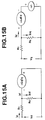
- Fig. 15A and 15B show the equivalent circuits of this control system, in which the respective circuits of the q-axis and d-axis are described and where V d is a d-axis component of an armature voltage, V q is q-axis component of an armature voltage of the q-axis, I d is a d-axis component of an armature current, I q is a q-axis component of an armature current, R1 is a resistance of the armature, R c is an equivalent iron-loss resistance, L d is a d-axis inductance, L q is a q-axis inductance, ⁇ is an angle frequency of an electric source, ⁇ is an interlinkage magnetic flux of the armature coil, I cd and I cq are current iron losses, and I d ' and I q ' are current loading.
- the q-axis current component I q ' is obtained from k*, the torque command T* and the magnetic flux ⁇ *.
- a multiplier 104 a d-axis current component is obtained by multiplying the current I q ' and k*.
- an adder 106 an output I q is obtained by adding I q ' and I cq (I q ' + I cq ).
- an iron loss current I cd is obtained by substituting the q-axis current component I q ' and the equivalent iron loss R c into the equation (26).
- the control output of the inverter 113 is obtained from the three-phase current values i u , i v and i w .
- a rotation speed detector PS of the motor 114 is connected to a position detecting circuit 111 for obtaining the output Q and a speed detecting circuit 115.
- the speed detecting circuit 115 output ⁇ which is send to the k calculating circuit 101, the ⁇ calculating circuit 102 and the R c calculating circuit 108.
- the exciting current calculating circuit 116 receives an output ⁇ from the ⁇ calculating circuit and outputs i f * to the DC current control circuit 117.
- step S10 When the judgement in the step S10 is "NO”, the program proceeds to a step S11 wherein it is judged whether T is smaller than T max or not.
- the program proceeds to a step S12 wherein it is judged whether ⁇ r is smaller than ⁇ r max or not.
- the program proceeds to END.
- a feedback of I d ' and I q ' may be implemented for the control of V d and V q .
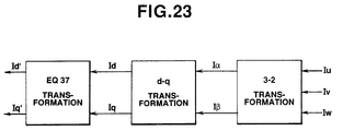
- a feedback of I d and I q is implemented from the output V u and V w of the PWM inverter, in order to obtain I d ' and I q ' from which iron-loss current has already eliminated, it is necessary to implement further transformation.
- Fig. 23 shows a feedback system of a modulation of a feedback system shown by a hatching in Fig. 21 upon taking into consideration with the equation (37). That is, d'-q' transformation represented by the equation (37) is implemented after the 3 ⁇ -2 ⁇ transformation and the d-q transformation.
- An area enclosed by a broken line shows a non-interference IP control system which eliminates iron-loss.
- a disturbance which can not be controlled independently in d-axis and q-axis, that is, an interference term, is K r ( ⁇ m + M f I f ) at the d-axis which is of an induced voltage due to the q-axis inductance and the d-axis inductance. and ⁇ kL d I q ' and ⁇ Kr( ⁇ m + M f I f ) at the q-axis which is of an induced voltage generated by the change of the magnetic flux by the DC field magnet current of q-axis.
- a feed-forward compensation is implemented relative to d-axis and q-axis as a control for eliminating the disturbance. That is, a feed-forward compensation of ⁇ (L d I q + ⁇ ) shown in Fig. 21 is implemented.
- Figs. 24 and 25 show an example of a non-interference processing by a feed-forward compensation, which is of a proportion-integral (PI) control system.
- a current control section between the table command and ⁇ - ⁇ transformation includes a proportion integral element K pd (1+1/ST Id ) ⁇ K pd (1 + 1/ST Iq ) , and feed-forward compensation elements ⁇ K r L d , ⁇ K ⁇ K q and ⁇ K r ( ⁇ m +M f I f ).
- Command values I d * and I q *, and feedback values I d ' and I q ' are inputted thereto and the command values V d * and V q * are outputted therefrom upon eliminating the disturbance. Accordingly, with this non-interference processing, d-axis and q-axis are independently separated as shown in Fig. 25, and therefore the performance of the control is improved.
- Figs. 26 and 27 show another embodiment of the non-interference processing of a IP control system.
- the structure of the IP control system of Fig. 26 is the same as that of the current control section shown in Fig. 21.
- the IP control system incudes a proportion elements K pd and K pq and feed-forward compensations ⁇ k r L d , ⁇ K r L q and ⁇ K r ( ⁇ m +M f I f ) in addition to integral elements K Id /S and K Iq /S. Accordingly, the control system of Fig. 26 also suppresses the disturbance.
- the non-interference processing shown in Fig. 27 it becomes possible to separate d-axis and q-axis, and therefore the control performance is improved.
- Figs. 24 and 25 show the PI control system which is implemented by using "primary delay” and Fig. 26 and 27 show IP control system which implemented by using "secondary delay”. That is, in PI control the difference between the command value and the feedback value is inputted to both the integral term and the proportion term, and V d * and V q * are outputted so as to decrease the difference to 0.
- V d * and V q * are outputted so as to decrease the difference to 0.
- the current values I d ', I q ' and I f of the interference term may be exchanged by the command I d *, I q * and I f *. That is, ⁇ K r L d I d ' to ⁇ K r L d I d '*, ⁇ K r L q I q ' to ⁇ K r L q I q '*, and ⁇ K r ( ⁇ m + M f I f ) to ⁇ K r ( ⁇ m +M f I f *).
- I f * is a DC exiting current command.
- Fig. 30 shows a PI control system by which non-interference processing is implemented.
- Fig. 31 shows a IP control system.
- the difference between Fig. 24 and Fig. 26 is that a coefficient relating to the iron loss is omitted.
- the embodiments in Figs. 30 and 31 are equivalent with embodiments that I d '*, I q '*, I d ' and I q ' are replaced with I d *, I q *, I d and I q , respectively in the embodiments of Figs. 25 and 27.
- the response characteristics of Figs. 30 and 31 are equivalent with the equations (38) and (39).
- I d , I q and I f of the interference term may be replaced with I d *, I q * and I f *, respectively.
Landscapes
- Engineering & Computer Science (AREA)
- Power Engineering (AREA)
- Control Of Ac Motors In General (AREA)
- Control Of Motors That Do Not Use Commutators (AREA)
- Control Of Direct Current Motors (AREA)
- Permanent Magnet Type Synchronous Machine (AREA)
Abstract
Description
- The present invention relates to method and apparatus for controlling a hybrid excitation type permanent magnet synchronous motor.
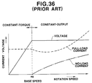
- Conventionally, a speed control of a permanent magnet synchronous motor has been implemented such that three-phase current or voltage for controlling the inverter is produced by detecting a rotation speed of the motor and compensating the rotation speed command by the feedback of the detected rotation speed. On the other hand, in a torque control the feedback of the detected rotation speed has been implemented to a current command instead of the rotation speed command. In case that a constant-output operation of such a motor is implemented by keeping the power source voltage constant, as a method for broadening operable speed area of the motor by raising the maximum rotation speed, a so-called demagnetization control has been proposed, in which an electric current is applied to an armature coil for canceling the magnetic flux of the permanent magnet, in order to equivalently reduce induced voltage. Fig. 36 shows a characteristic curve obtained from such a demagnetization control.
- It is an object of the present invention to a control method and control system of a hybrid excitation type permanent magnet synchronous motor, which control method and system enable the operable speed range of the motor to be further broadened.
- A motor control method according to the present invention is for a hybrid excitation type synchronous motor which has a field of a permanent magnet and a dc excitation coil. The motor is arranged such that magnetic flux of the field is controlled by adjusting dc electric current of the dc excitation coil. The method includes the steps of: controlling the magnetic flux of the field so as to keep constant when a rotation speed of the motor is smaller than a predetermined base speed and so as to change in reverse proportion with the rotation speed of the motor when the rotation speed is larger than the predetermined base speed; controlling electric current and voltage to the armature such that a current ratio of a direct-axis component and a quadrature-axis component which components are obtained by dividing an electric current to the armature coil into the direct-axis component and the quadrature-axis component relative to the voltage induced in the armature coil, is kept constant; and selecting at least one of the magnetic flux control and current-and-voltage control to control the motor.
- Further according to the invention, there is provided a control system for a hybrid excitation type synchronous motor which has a field of a permanent magnet and a dc excitation coil. The motor is arranged such that magnetic flux of the field is controlled by adjusting dc electric current of the dc excitation coil. the control system is comprised of first control means which controls the magnetic flux of the field so as to keep constant when a rotation speed of the motor is smaller than a predetermined base speed and so as to change in reverse proportion with the rotation speed of the motor when the rotation speed is larger than the predetermined base speed. Second control means controls electric current and voltage to the armature such that a current ratio of a direct-axis component and a quadrature-axis component which components are obtained by dividing an electric current to the armature coil into the direct-axis component and the quadrature-axis component relative to the voltage induced in the armature coil, is kept constant. Selecting means selects at least one of the first and second control means to control the motor.
-
- In the drawings, like reference numeral designate like parts and elements throughout all figures, in which:
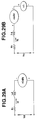
- Fig. 1 is a structural view of a hybrid excitation type permanent magnet motor controlled by a control method according to the present invention;
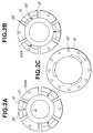
- Fig. 2A, 2B and 2C are structural views of a rotor of the motor of Fig. 1;
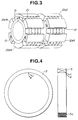
- Fig. 3 is a perspective view of a rotor of the motor Fig. 1;
- Fig. 4 is a structural view of an exiting coil of the motor of Fig. 1;
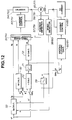
- Fig. 5 is a block diagram of a first embodiment of a motor control system of a hybrid excitation type permanent magnet motor according to the present invention;
- Fig. 6 is a characteristic curve between a torque and a value K of Fig. 1;
- Fig. 7 is a characteristic curve between Λ and ω;
- Fig. 8 is a block diagram of a second embodiment of a motor control system according to the present invention;
- Fig. 9 is a block diagram of a speed control circuit;
- Fig. 10 is a block diagram of a third embodiment of the motor control system according to the present invention;
- Fig. 11 is a characteristic curve between Λ and ω of Fig. 10;
- Fig. 12 is a block diagram of a fourth embodiment of the motor control system according to the present invention;
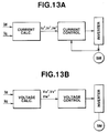
- Fig. 13A a block diagram of a current control type inverter, and Fig. 13B is a block diagram of a voltage control type inverter;
- Fig. 14 is characteristic curves which show differences among efficiencies of the embodiments;
- Figs. 15A and 15B are equivalent circuits of d-axis and q-axis;
- Fig. 16 is a block diagram of a HPM control system;
- Fig. 17 is a another block diagram of a HPM control system;
- Fig. 18 is a flow chart which indicates a method for calculating k-table and Λ-table;
- Fig. 19 is an explanatory view for the calculation of k;
- Fig. 20 is an efficiency map of a motor which is obtained by a simulation;
- Fig. 21 is a block diagram of a practical system;
- Fig. 22A and 22B are equivalent circuits including a transient condition;
- Fig. 23 is a modification of a control section of Fig. 21;
- Fig. 24 is a block diagram of a non-interference PI control;
- Fig. 25 is a block diagram of the d-axis and q-axis of Fig. 24;
- Fig. 26 is a block diagram of a non-interference IP control;
- Fig. 27 is a block diagram of the d-axis and q-axis of Fig. 26;
- Figs. 28A, 28B and 28C are explanatory views which show a difference between the PI control and the IP control;
- Figs. 29A and 29B are equivalent circuits where iron loss is neglected and a transient condition is included;
- Fig. 30 is a block diagram of a non-interference PI control;
- Fig. 31 is a block diagram of a non-interference IP control;
- Fig. 32 is a block diagram of a PI control on the basis of a voltage model taking into consideration with the iron loss;
- Fig. 33 is a block diagram of a PI control on the basis of a voltage model neglecting iron loss;
- Fig. 34 is a block diagram of a control system of PM;
- Fig. 35 is an efficiency map obtained by a simulation of the PM; and
- Fig. 36 is a characteristic curve in the torque-constant area and the output-constant area of a conventional motor control.
- Figs. 1 to 4 show a structure of a hybrid excitation type permanent magnet synchronous motor whose control is realized by a method and control system according to the present invention.
- As shown in Fig. 1, an
armature 1 of a stator is constituted by anarmature core 2, anarmature coil 3 and acylindrical yoke 4. Thearmature core 2 is divided into two parts in the axial direction of the motor. One side of thearmature core 2 is a N-pole core 2a, and the other side of thearmature core 2 is a S-pole core 2b. A ring-shaped DC (direct current)excitation coil 5 as shown in Fig. 4 is disposed between the N-pole core 2a and the S-pole core 2b. The N-pole and S-pole cores 2a and 2b are magnetically connected with each other through theyoke 4 and mechanically supported by theyoke 4. Thearmature coil 3 is disposed so as to cross the N-pole and S-pole cores 2a and 2b. Theexcitation coil 5 is formed by winding awire 5a and treating it by the insulation process. The number of turns of theexcitation coil 5 is adjusted so as to generate a necessary magnetmotive force upon matching with a capacity of the electric source and the machinery dimension. - A rotor 11 is constituted by a
rotor core 12 and a plurality of permanent magnets (PM) 13. Therotor core 12 is fixedly supported to ayoke 14 connected to ashaft 15. Therotor core 12 hassalient pole portions 12a which project form therotor core 12 and function as a salient pole, and thesalient pole portions 12a are disposed at portions where thepermanent magnets 13 are not located. As shown in Figs. 1, 2A and 2B, thepermanent magnet 13 is embedded in the rotor 11 and covered with therotor core 12. Aslit 20 is formed between eachpermanent magnet 13 and each polesalient portion 12a in relation that thepermanent magnets 13 and thesalient pole portions 12a are fixed on the yoke. In order to reinforce the rotor 11,non-magnetic reinforcement plates 21 as shown in Fig. 2C are disposed in the several portions in the axial direction. Thenon-magnetic reinforcement plates 21, thesalient pole portions 12a and therotor cores 12 are integrally fitted with each other by inserting aluminum-alloy die-cast member or copper bar toslots 22. The inserted member and a pair of end rings installed at an axial end form an electric current passage. Thesalient pole portions 12a are divided into N-pole salient pole portions 12aN and S-pole salient pole portions 12aS which are dividedly disposed so as to be opposite to the N-pole and S-pole cores 2a and 2b, respectively. Thepermanent magnets 13 are fixedly attached on therotor core 12, and therotor core 12 is inserted into theyoke 12 to be supported thereby. - The N-pole and S-pole salient pole portions 12aN and 12aS are formed such that the length thereof corresponds to those of the N-
pole core 2a and the S-pole core 2b, respectively, and that width thereof are constant along the circumferential direction. Further, the N-pole salient pole portions 12aN are arranged side by side with the N-pole side of thepermanent magnets 13, as shown in Fig. 2A. The S-pole salient pole portions 12aS are arranged side by side with the S-pole sides of thepermanent magnets 13, as shown in Fig. 2B. Furthermore, the N-pole salient pole portion 12aN and the S-pole side of thepermanent magnets 13 are aligned along the axial direction of the motor at predetermined intervals. Similarly, the S-pole salient pole portion 12aS and the N-pole side of thepermanent magnets 13 are aligned along the axial direction of the motor at predetermined intervals. - That is, the rotor 11 is formed as shown in Fig. 3, in which the N-pole salient pole portions 12aN and the N-pole side of the
permanent magnets 13 are alternately arranged in the circumferential direction. The S-pole salient pole portions 12aS and the S-pole side of thepermanent magnets 13 are alternately arranged in the circumferential direction. Furthermore, the arrangement units of the N-pole side and the S-pole side are separated with each other by a width of theexcitation coil 5, and thesalient pole portions 12a and thepermanent magnets 13 are aligned in the axial direction. The number of thesalient pole portions 12a is the same as that of thepermanent magnets 13. - Although the motor in Figs. 1 to 3 has been shown and described such that the
permanent magnet 13 is disposed at six poles, it will be understood that the number of the poles does not limited to six. Furthermore, while the motor of Figs. 1 to 3 has been shown and described such that the surface of thesalient pole portion 12a and that of thepermanent magnet 13 are located within a same circumferential surface, thesalient pole portions 12a may be formed to further project toward thearmature 1 so as to reduce the gap between thesalient pole portions 12 and thearmature 1. This arrangement will cause an effect that the magnetic flux passing through thesalient pole portions 12 is increased. Because of the same reason, the width of thesalient pole portions 12a may be broadened. - Referring to Figs. 6 to 35, there are shown embodiments of a control system of the above-mentioned motor, according to the present invention.
- In general, a quadrature-axis reactance


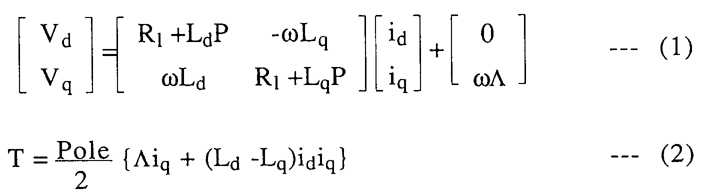
where Vd is a voltage on a direct-axis, Vq is a voltage on a quadrature-axis, id is a current on the direct-axis, iq is a current on the quadrature-axis, Rl is a coil resistance, Λ is the number of an interlinkage magnetic-flux lines, Pole is the number of poles, and P is a differential operator
- In general, Λ can be generally expressed by a function of a direct-current excitation current If, that is,

- Above-described equations are used as a basic equation in a wide-range variable speed control method of a motor having a DC exciting-current coil.
-
- The manner of operation of the control of a brushless DC motor in a permanent magnet embedded type hybrid excitation type permanent magnet motor will be discussed hereinafter.
- In a normal brushless DC motor, assuming that Id is set at 0 (Id = 0), only Iq is applied to the motor, and Λ is controlled such that Λ is kept constant at a speed lower than a base speed and Λ is varied in reverse-proportion with a rotation speed of the motor at a speed higher than a base speed to ensure a constant-output properties; a constant-torque output characteristic is obtained. In this case, the generated torque is represented by the following equation (3):

Fig. 5 shows a control system of a brushless DC motor in that Id is kept at 0 (Id = 0 control). The control system is of a speed control system whose main circuit comprises atorque calculator 30 for obtaining a torque T* from a command speed ω*, an electriccurrent calculator 31 for obtaining a quadrature-axis electric current Iq form the torque T*, a three-phase electriccurrent calculator 31 for obtaining a three-phase electric current from the quadrature-axis electric current by applying the equation (3) and the following equations (4), acurrent controller 33, and aninverter 35.


where ϑ is a rotor position angle,
- A rotation speed of the
motor 35 is controlled by theinverter 34 and detected by arotation speed detector 35. The detected signal by therotation speed detector 35 is inputted as a rotational position to the three-phasecurrent calculator 32 through aposition detecting circuit 37. Further, the detected signal by therotation speed detector 36 is modulated as a present speed in aspeed detecting circuit 38 and is then added to the speed command ω*. The modulated signal at thespeed detecting circuit 38 is transformed into a field-magnet magnetic flux Λ at ancalculator 39. An excitationcurrent calculator 40 obtains an electric current if from the field magnetic-flux, and a DC electriccurrent control circuit 41 is controlled according to the obtained electric current if. Accordingly, the exciting current is varied according to the speed such that the field magnetic-flux Λ is kept constant when the speed is lower than a base speed and is gradually decreased in reverse proportion with the speed when the speed is higher than the base speed. This control extends an operable speed area of themotor 35. - If the control system of Fig. 5 is used as a torque control, the left hand side part divided by a broken line of Fig. 5 is not necessary in such a torque control system.
- In addition to the above-mentioned current control, this embodiment provides a further improved control by which the
motor 30 is operable in a further high-speed a high-torque control by utilizing the characteristics that the quadrature-axis reactance of thismotor 35 is large. Assuming that themotor 35 is put in a stationary condition in that R₁ is neglected since the R₁ is extremely small as compared with the reactance in the equations (1) and (2), the equations (1) and (2) are expressed by the following equations (5) and (6):


If the equation (5) is applied to a high-speed condition, ωΛ and Id become considerably large. Therefore, the equation (5) is applied only for a low-speed and/or low-load operation. The voltage of the motor terminal is obtained from the equation (5) as follows: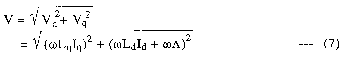
When a possible output voltage of the inverter is Vmax, the motor is operable within the range in that V ≦ Vmax. That is, the operable range of the motor is under a condition V ≦ Vmax. - It is assumed that the ratio between Id and Iq is constant in order to uniformly determine the electric current relative to the torque command. That is, when the ratio between the Id and Iq is K, the following equation (8) is obtained.

By applying the equation (8) to the equation (6), the following equation (9) is obtained.
As is clear from the equation (9), if the magnetic flux Λ is constant and the torque T is obtained, the electric current Iq is obtained. - In order to obtain an experimental data relative to the value K, as to a hybrid excitation type permanent magnet motor designed as a 45kW-8 pole motor, the relationship between the value K and the torque was searched in a condition that Il is kept at 200A (Il = 200A). Fig. 6 shows such examination data which indicates that the torque T is largely varied according to the value K. The result of Fig. 6 indicates that it is preferable to set the value K within a range from -0.3 to -1.2 as compared with the control at K= 0 (Id = 0), in order to effectively obtain the output torque T. Although the torque T is determined from the valve K and the primary current, it is preferable to set K < 0 in a K value constant control in order to obtain a high-torque relative by the small electric current.
- If the value K is determined as mentioned above and the interlinkage magnetic flux Λ is varied within the torque-constant range and a speed higher than the base speed as shown in Fig. 7, the electric current value Iq is univocally determined relative to the torque T. In Fig. 7, Λmax is a maximum value of Λ which is determined from the magnetic saturation, and Λ is a multiple of Λmax and the speed ratio


where Q is a rotor position angle,

- As a result, if the K value is set at minus, the direct-axis current Id becomes minus. This lowers Vq and the operable range of the motor is extended.
- Fig. 8 shows a block diagram of a Id- Iq ratio constant control system of a torque control circuit. The quadrature-axis current Iq is obtained from the torque command T* and a feed-back magnetic flux command Λ in a
calculator 50. a three-phase current calculator receives the Iq and the Id obtained by the multiple of the Iq and K. The electric current values iu, iv, iw of the equation (10) are outputted from the three-phasecurrent calculator 51 and inputted to aninverter 54 through acurrent controller 53. Upon receipt of the electric current, theinverter 54 is operated. - The detected value by a
rotation speed detector 56 for amotor 55 is inputted to the three-phasecurrent calculator 50 after modulated as a rotational position in aposition detecting section 57. Aspeed detecting section 58 receives the detected value at therotation speed detector 56 and outputs a speed ω. The speed ω is inputted to acalculator 59, which has a property shown in Fig. 8, outputs the magnetic flux Λ. The output Λ from thecalculator 59 is inputted to the Iq calculator 50 and an exitingcurrent calculator 60. An electric current if is outputted from the excitingcurrent calculator 60 and inputted to a DCcurrent controller 61. - Fig. 9 shows a speed control circuit to which a speed command ω* is inputted. The speed control circuit is generally similar to the torque control circuit of Fig. 9 except that a
torque calculator 62 for calculating a torque command T* from the speed command ω* is provided in front of the Iq calculator 50 and a feed back command from aspeed detecting section 58 is added to the speed command ω*. - Although at low-speed range of light-loading the operating property of the motor is improved by changing the magnetic flux Λ while keeping K constant, in this high-speed or heavy-loading the voltage V in the equations (6) and (7) frequently exceeds the maximum voltage Vmax of the inverter due to the increase of the speed ω. Accordingly, in this control the motor is operated by keeping the voltage V at Vmax (


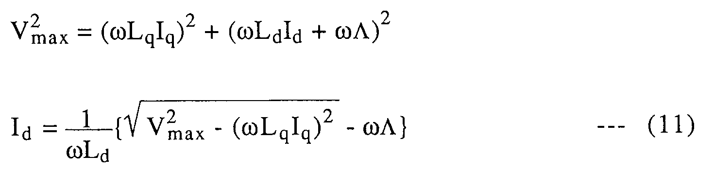
Although the equation (11) shows Iq for keeping the terminal voltage at Vmax, in order to facilitate the control, the root part of the equation (11) is set at 0
That is, so as to satisfy the equation (12) the magnetic flux Λ is changed for the control of torque.

When Iq is controlled according to the equation (12), Id is represented as follows:

By substituting the equations (12) and (13) into the equation (6), the following equation (14) is obtained.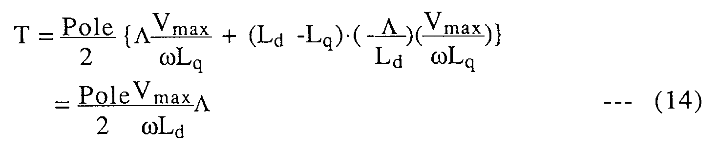
As is clear from the equation (14), when the speed ω is kept constant, the torque T is in proportion with the number Λ of the interlinkage magnetic flux. Accordingly, the torque control is carried out by controlling Λ. In this control, From the equations (5) and (13),
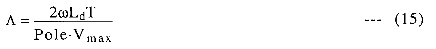
As a result, Vmax of the equation (15) is decided by the inverter, and by obtaining Λ after the detection of ω, Iq and Id represented by the equations (12) and (13). Accordingly, it is possible to extend the operable range of the motor by controlling Iq and Id so as to keep Vmax constant, that is, by keeping Vq = 0. - Since Λ is saturated if too large, it should be kept to be smaller than Λmax. That is, the maximum torque is limited by the following equation (16):

Fig. 10 shows a block diagram of the above-mentioned Vq=0 control system. As shown in Fig. 10, aΛ calculator 70 executes the calculation of Λ represented by the equation (15) upon receiving the torque command T* and the speed command ω*. Then, limiter 71 limits Λ within Λmax. Id-calculator 72 executes the calculation of Id from the equation (13), and Iq-calculator 73 executes the calculation of Iq from the equation (12). Following this, a three-phasecurrent calculator 74 calculates the current values iu, iv and iw, and the obtained valves are used for driving theinverter 76 through thecurrent control section 75. - The detected value by the
rotation speed detector 78 for themotor 77 is modulated as a rotational position at aposition detecting section 79 and inputted to a three-phasecurrent calculator 74. Further, the detected value by therotation speed detector 78 is inputted to aspeed detecting section 80 where the speed ω is outputted. The outputted speed ω is feed-backed to theΛ calculator 70 and the Iq calculator 73. - The output Λ of the
limiter 71 is inputted to the Id calculator 72 and the excitingcurrent calculator 81 for obtaining the current if. A DC electriccurrent control circuit 82 is controlled according to Id and if. - Although Fig. 10 shows a torque control circuit, by adding the speed feedback and the
torque calculator 62 shown in a left side portion divided by the broken line in Fig. 9, the control circuit of Fig. 6 can be used as a speed control circuit. - Accordingly, by suppressing Vmax so as to implement Vq= 0 control, the terminal voltage V is decided. This control becomes suitable for the heavy-loading and high-speed range control.
- In order to smoothly implement a wide-range speed control, it is necessary to interconnect the Id-Iq ratio-constant control and the Vq= 0 control. Although it is possible to properly select the value K (Id-Iq ratio), it is necessary to select the value K so as to avoid discontinuous of the electric current and the magnetic flux at a transient between the Id-Iq ratio-constant control and the Vq= 0 control.
- During the Vq = 0 control,


By substituting the equation (17) to the above-mentioned equation

Further the following equation (19) is obtained from the equation (18).

Although the speed ω is variable in the equation (19), in the output-constant operation range during the Id-Iq ratio constant control, Λω is kept at a constant value E₀ and therefore the induced voltage becomes constant, as shown in Fig. 11. As a result, if the motor is designed so that the switching of the control method is implemented within the constant-output operation range, the value K can be defined by the following equation (20):

Accordingly, it becomes possible to implement the K constant control within the constant-output operation range, and therefore the switching between the controls may be implemented when the speed of the motor is higher than the base-speed. That is, the switching from the Id-Iq ratio constant control to the Vq= 0 control may be implemented when
- When the motor is controlled such that Id and Iq satisfy the equations (13) and (17), the following equations (21) and (22) are obtained:

By compounding the control systems of Figs. 8 and 10 in consideration with the equations (21) and (22), the control system of Fig. 12 is obtained. In Fig. 12, the switching between the Id-Iq ratio constant control and the Vq = 0 control is implemented by the switching of switches SW₁, SW₂, and SW₃. When the Iq calculator 50 calculates the following equation (23) is implemented, the switches SW₁ and Sw₂ are connected to a-contact side, and the switch SW₃ is opened. On the other hand, when the Iq calculator 50 calculate the following equation (24), the switches SW₁ and SW₂ are connected to b-contact, and the switch SW₃ is closed. - When

When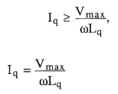
If a speed feedback element is applied to the control system of Fig. 12, it becomes a speed control system. - Although the embodiments of the control system have been shown and described to comprise the
inverter current control section - With the above-mentioned embodiments of the motor control system according to the present invention, it is possible to extend the operable range of the PM motor which includes a DC field magnet coil. Furthermore, it is possible to form the motor more smaller and to improve the efficiency due to the increase of the maximum torque and the raising of the maximum rotation speed. This further enables the current capacity of the electric source to be smaller.
- In concrete, the experiment by the motor of 45kW-8P 3000rpm was implemented, and the data as shown in Fig. 14 was obtained. As is clear from the data of Fig. 14, the
operable range ① of a field magnet control is extended as compared with theoperable range ⑤ in case of no- field magnet control. By the Id-Iq ratio constant control, the operable range is further extended as shown by theline ②, and by the Vq = 0 control within a constant-output range the operable range thereof is extended as shown by theline ③. Further, maximum advantage is obtained by the combination of Id-Iq ratio control and the Vq = 0 control as shown by theline ④. - Hereinbefore, the control method such as a high-speed range and heavy-loading control, and a wide-range speed control of the brushless DC motor, which control method is implemented by obtaining I or V on the basis of the voltage equation, has been mentioned.
- Next, another control method will be discussed hereinafter. The control method is a method for deciding the current ratio and the magnetic flux by taking account the iron loss and using previously prepared a current ration (k) table and a magnet flux (Λ) table.
- Fig. 15A and 15B show the equivalent circuits of this control system, in which the respective circuits of the q-axis and d-axis are described and where Vd is a d-axis component of an armature voltage, Vq is q-axis component of an armature voltage of the q-axis, Id is a d-axis component of an armature current, Iq is a q-axis component of an armature current, R₁ is a resistance of the armature, Rc is an equivalent iron-loss resistance, Ld is a d-axis inductance, Lq is a q-axis inductance, ω is an angle frequency of an electric source, Λ is an interlinkage magnetic flux of the armature coil, Icd and Icq are current iron losses, and Id' and Iq' are current loading.
- As is clear from Figs. 15A and 15B, the current values Id, Iq, Icd and Icq are obtained by the following equations (25) and (26):


When Λm is an interlinkage magnetic flux only by the permanent magnet, Mf is a mutual inductance of a field magnet coil and an armature coil, and If is an exciting current, the following equation (27) is obtained.

The following equations (28) and (29) are obtained by providing a voltage equation of Figs. 15A and 15B according to the equations (25) and (26).
where
Furthermore, the equation of the torque can be represented by the following equation (30):
where Pole is the number of poles. - As a result, when the hybrid excitation type permanent magnet synchronous motor is operated by the torque control, the operation is accomplished by controlling Id', Iq' and Λ.
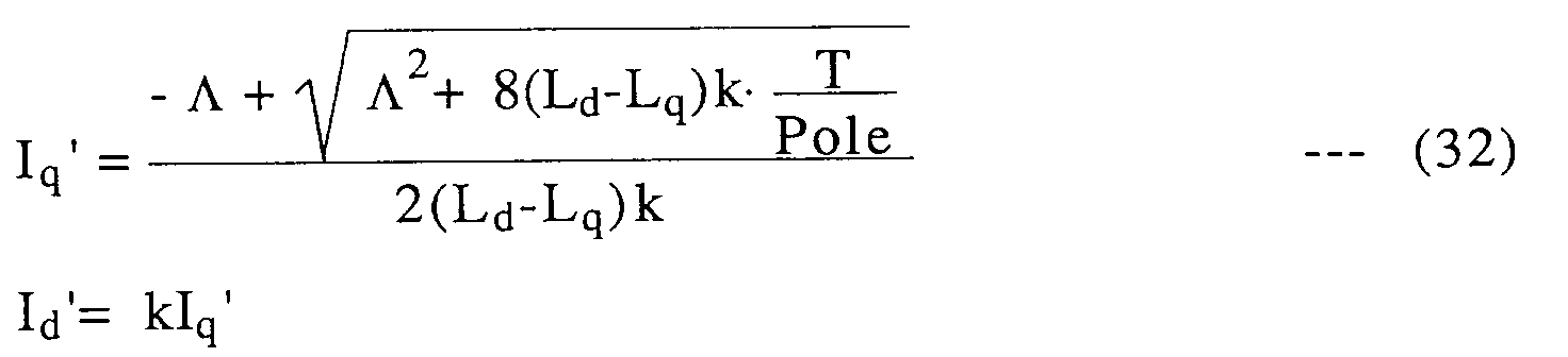
- If it is defined that
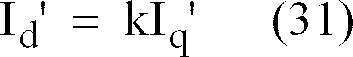

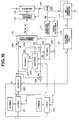
As is clear from the equation (32), when the current ratio k of the d-axis component of current and the q-axis component of it and the magnetic flux Λ relative to the proper speed ωr and torque T can be obtained, it is possible to decide the current Iq'. - Hereinafter, the field magnet control method and the creating method of the control table will be discussed with reference to Figs. 16 to 35. Fig. 16 shows a block diagram of a control system of the hybrid excitation type permanent magnet synchronous motor of a current control type. In Fig. 16, the torque command T* is inputted to the
k calculating circuit 101 and aΛ calculating circuit 102, and an appropriate values k* and Λ* corresponding to the speed ω are selected from the k-table and the Λ-table, respectively, in thecircuit - In a Iq' calculating
circuit 103, the q-axis current component Iq' is obtained from k*, the torque command T* and the magnetic flux Λ*. In amultiplier 104, a d-axis current component is obtained by multiplying the current Iq' and k*. In anadder 106, an output Iq is obtained by adding Iq' and Icq (Iq' + Icq). In a Icd calculator 107, an iron loss current Icd is obtained by substituting the q-axis current component Iq' and the equivalent iron loss Rc into the equation (26). the output Id is obtained by adding Id' and Icd (Id' + Icd) in anaddor 109. In a three-phase currentcalculating circuit 110, three-phase current iu*, iv* and iw* are obtained by substituting the outputs Iq and Id, and the output q into the following equations (33):


where ϑ is a rotor position angle and

- In a
current control circuit 112, the control output of theinverter 113 is obtained from the three-phase current values iu, iv and iw. A rotation speed detector PS of themotor 114 is connected to a position detecting circuit 111 for obtaining the output Q and aspeed detecting circuit 115. Thespeed detecting circuit 115 output ω which is send to thek calculating circuit 101, theΛ calculating circuit 102 and the Rc calculating circuit 108. Further, the exciting currentcalculating circuit 116 receives an output Λ from the Λ calculating circuit and outputs if* to the DCcurrent control circuit 117. - Fig. 17 shows a block diagram of a motor control system of a voltage control type. The voltage control type control system is generally similar to the current control type of Fig. 16 expect that a three-phase voltage
command calculating circuit 118 is used instead of the three-phase current calculating circuit 111 so as to output voltage output Vu*, Vv* and Vq* to theinverter 113. - Hereinafter, the calculation of the k-table of the
k calculating circuit 101 and the Λ-table of theΛ calculating circuit 102 will be discussed with reference to Figs. 16 and 17. - When the torque command T is commanded and the speed ω is applied to the control system, k and Λ, which satisfy the inputted torque T and speed ω, infinitely exist. Accordingly, it is possible to implement the maximum torque control an the maximum efficiency control by the value k (the ratio between Id' and Iq') and the magnetic flux Λ.
- In case that the maximum efficiency control is implemented, the following equations (32), (26) and (25) are satisfied relative to arbitrary k and Λ.
where during operation Iq' > 0, and k< 0 (T>0); and during regenerating Iq'< 0, and k > 0 (T>0).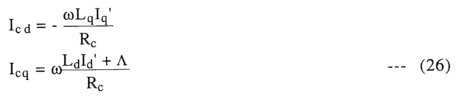

The terminal voltage V₁ is represented by the following equation (34) from the equation (28), and the primary voltage I₁ is represented by the following equation (35).


Further, the various losses of the motor are represented as follows:
Inverter Loss;
Motor Loss
Primary Loss;
Iron Loss;
where
Machine Loss;
Stray Loss;
As a result, a total loss can be represented as follows:

Accordingly, an efficiency η is represented as follows: - (1) during driving,

- (2) during regenerating,

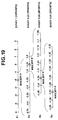
- The derivation of the k-table and the Λ-table is implemented according to a flow chart shown in Fig. 18.
- In a step S₁, the speed ωr is initialized (ωr = 0), in a step S2 the torque T is initialized (T = 0), in a step S3 the value k is set to kmin (

- In a step S5, on the basis of k and Λ, Id and Iq are calculated. Following this, in a step S6 the total efficiency η is calculated. In a step S7, it is judged whether the total efficiency η is higher than the MAXEFF or not. When the judgement in the step S7 is "YES", the program jumps to a step S9. When the judgement in the step S7 is "NO", the program proceeds to a step S8 wherein MAXEFF = η and k and Λ are stored. In the step S9 it is judged whether Λ is smaller than Λmax or not. When the judgement in the step S9 is "YES" (Λ<Λmax), the program proceeds to a step S13 wherein Λ is incremented by


- In this flow chart, if ΔΛ and Δk is too small, the amount of the points to be calculated becomes too large. Accordingly, the ΔΛ and Δχ are decreased step by step.
- For example, when the hybrid excitation type permanent magnet synchronous motor of 45kw is operated by varying the speed ωr and the torque T from 0 to maximum, respectively, ωr and the torque T is varied as follows:


At the 110 (10 × 11) points of the operating points, the efficiency is calculated by varying k and Λ as follows:


- The varying of k is implemented as shown in Fig. 20, that is, first Δk = 1 (10 points), next Δk = 0.25 (7 points), third Δk =0.05 (9 points), and then Δk =0.01 (9 points). Accordingly, Λ may be varied from o.3 Λmax to Λmax relative to the 35 points of k.
- The simulation data of the coefficient k and ΔΛ of the hybrid excitation type permanent magnet synchronous motor is shown as follows:
45kw - 8P-3000rpm
R₁ = 0.01582 (Ω)
Ld = 0.299 (mH) Lq = 0.192 (mH)
L₀ = 0.186
Inverter loss coefficient
k₁ = 0.0156/2 k₂= 9.02/2
The k-table and Λ-table were obtained as shown in the following Tables 1 and 2.

- As a result, the efficiency of the motor was obtained as shown in a map of Fig. 20, and the MAXEFF was 95% (MAXEFF=95%).
- Although the maximum efficiency operation as mentioned above is implemented by making the k-table and the Λ-table, such a table making complicates the calculation thereof in the practical control system. Accordingly, in order to shorten the time for the calculation, the exciting current Id, the torque current Iq and the magnetic flux Λ, by which the maximum efficiency is obtained relative to the arbitrary operating points, are made into a table. In this case, the algorithm for making tables of Id and Iq is the same as that of the k-table and the Λ-table. That is, Id and Iq obtained from k and Λ are made into a table, and the Λ-table which is the same as that of the previous case is used. Since the command current is directly made into table, it is necessary to make the table by using small steps.
- For example, assuming that the parameter of the motor is the same as that of the previous case, the rotation speed ωr and the torque T are varied as follows:


Since such steps are calculated by a CPU, the number of steps is 2X ( X is natural number). The k-table and Λ-table are obtained within the following range.


Accordingly, the number of Id, Iq, Λ data becomes 2193 ((128 +1) × (16 + 1) = 2193). The data is interpolated. - Fig. 21 shows a block diagram of the maximum efficiency control system which is practically used. The commands Id*, Iq* and Λ* are outputted from the Id-table, Iq-table and Λ-table. Vd* and Vq* are obtained therefrom and pass through a d-axis-q-axis coordinate transformation section and a 2φ - 3φ transformation section, and are used for the control of a PWM inverter, that is, the armature voltage. The command Λ* is transformed into Vf* and is used for the field magnet control at a PWM chopper.
- A counterplan for disturbance is included in the control system shown in Fig. 21. That is, an enclosed area by a broken line in Fig. 21, which is disposed between the command Id*, Iq* and the coordinate transformation (α-β transformation), includes an integral element (I element), KId/S, KIq/S, an adding proportion element (P element), Kpd, Kpq and adding elements ωLqIq, ω(LdId +Λ). The integral element and the proportion element are provided for compensating a transient term and a normal term in the previous voltage equation and integral and adding in a feedback system. The adding element indicates an interference term and a compensation in a feed-forward system.
- The disturbance in the equivalent circuit and the voltage equation will be discussed hereinafter. That is, Iq, Id and Λ are previously made into tables as shown in Fig. 21 for obtaining maximum efficiency of k-table and Λ-table, and the current control is independently implemented on the respective d-axis and q-axis, in actual case. Accordingly, the disturbance is generated in the respective axes and degrades the performance of the control. In Fig. 22, taking into consideration with the iron loss of a typical disturbance, a voltage equation for an equivalent circuit of Fig. 22 including a transient condition is obtained as follows:

where R₁ is an armature resistance; Rc is a equivalent iron-loss resistance; Ld is a d-axis inductance; Lq is a q-axis inductance; Λ is an interlinkage magnetic flux of the armature coil; w is an electric source angle frequency; Vd is a d-axis component of the armature voltage; Vq is a q-axis component of the armature voltage; Id is a d-axis component of the armature current; Iq is a q-axis component of the armature current; P is a deferential operator; and k₁ is
- Furthermore, Id, Iq, Icd and Icq in Figs. 22A and 22B are represented by the equations (25) and (26), and


Fig. 23 shows a feedback system of a modulation of a feedback system shown by a hatching in Fig. 21 upon taking into consideration with the equation (37). That is, d'-q' transformation represented by the equation (37) is implemented after the 3φ-2φ transformation and the d-q transformation. An area enclosed by a broken line shows a non-interference IP control system which eliminates iron-loss. - In the voltage equation (36) and the equivalent circuits of Figs. 22A and 22B, a disturbance, which can not be controlled independently in d-axis and q-axis, that is, an interference term, is Kr(Λm + MfIf) at the d-axis which is of an induced voltage due to the q-axis inductance and the d-axis inductance. and ωkLdIq' and ωKr(Λm + MfIf) at the q-axis which is of an induced voltage generated by the change of the magnetic flux by the DC field magnet current of q-axis. Therefore, a feed-forward compensation is implemented relative to d-axis and q-axis as a control for eliminating the disturbance. That is, a feed-forward compensation of ω(LdIq + Λ) shown in Fig. 21 is implemented.
- Hereinafter, a current control section for a feed-forward compensation and a feed-forward system will be discussed.
- Figs. 24 and 25 show an example of a non-interference processing by a feed-forward compensation, which is of a proportion-integral (PI) control system. A current control section between the table command and α-β transformation includes a proportion integral element

- In this case, if the proportion gain of d-axis is


Accordingly, a response characteristic is determined by the characteristic angle frequency ωc. Similarly, the same relationship as to the q-axis is obtained by assuming that

- Figs. 26 and 27 show another embodiment of the non-interference processing of a IP control system. The structure of the IP control system of Fig. 26 is the same as that of the current control section shown in Fig. 21. The IP control system incudes a proportion elements Kpd and Kpq and feed-forward compensations ωkrLd, ωKrLq and ωKr(Λm +MfIf) in addition to integral elements KId/S and KIq/S. Accordingly, the control system of Fig. 26 also suppresses the disturbance. By the non-interference processing shown in Fig. 27, it becomes possible to separate d-axis and q-axis, and therefore the control performance is improved.
- In this case, if the proportion gain is


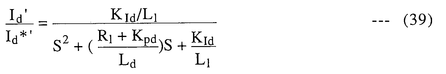
Since this equation (39) is the same as a transfer function of a general secondary filter, it is represented as follows: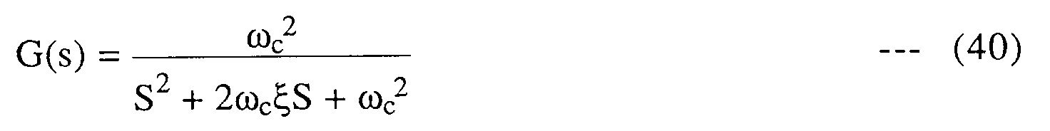
where ωc is a characteristic angle frequency; and ξ is a damping coefficient. - Accordingly, a current response is determined by the characteristic angle frequency ωc and the damping coefficient ξ. Similarly, the same relationship as to the q-axis is obtained by the similar assumption.
- Figs. 24 and 25 show the PI control system which is implemented by using "primary delay" and Fig. 26 and 27 show IP control system which implemented by using "secondary delay". That is, in PI control the difference between the command value and the feedback value is inputted to both the integral term and the proportion term, and Vd* and Vq* are outputted so as to decrease the difference to 0. By the implementation of non-interference processing, it becomes possible to control the response of the motor current (Id, Iq) as "primary delay", as shown in Fig. 28A and by changing the gains (Kpd, Kpq) as shown in Fig. 28B, it can be treated as an arbitrary primary delay.
- On the other hand, In IP control the difference between the command value and the feed back value is inputted only to the integral term, and the feed back value is inputted to the proportion term. Further Vd* and Vq* are outputted so as to decrease the difference to O. By the non-interference processing, it becomes possible to control the motor current by the secondary delay as shown in Fig. 28C, and the secondary delay is arbitrarily determined by changing the gains (Kpd, KId, Kpq and KIq). Since the number of the gains to be changed is larger than that of the gain of the PI control, the degree of freedom of the response wave is increased. Further, it is possible to increase the response speed of the IP control rather than that of the PI control by the proper selection of the gain constituted by the same sample frequency.
- When large quantity of noises are occurred in the feedback signals Id and Iq in the control systems of Figs. 24 and 26, the current values Id', Iq' and If of the interference term may be exchanged by the command Id*, Iq* and If*. That is, ωKrLdId' to ωKrLdId'*, ωKrLqIq' to ωKrLqIq'*, and ωKr(Λm + MfIf) to ωKr(Λm+MfIf*). Where If* is a DC exiting current command.
- In the above explanation, the equivalent circuit including a transient condition taking account the iron loss is applied as promise. Figs. 29A and 29B show equivalent circuits including the transient condition in case that the iron loss is neglected and corresponds to a case that the resistance Rc in the circuits of Figs. 22A and 22B is set infinity (∞). The voltage equation in this case is represented by the following equation (41).

When


- Fig. 30 shows a PI control system by which non-interference processing is implemented. Fig. 31 shows a IP control system. The difference between Fig. 24 and Fig. 26 is that a coefficient relating to the iron loss is omitted. The embodiments in Figs. 30 and 31 are equivalent with embodiments that Id'*, Iq'*, Id' and Iq' are replaced with Id*, Iq*, Id and Iq, respectively in the embodiments of Figs. 25 and 27. Further, the response characteristics of Figs. 30 and 31 are equivalent with the equations (38) and (39). Furthermore, it is a matter of fact that Id, Iq and If of the interference term may be replaced with Id*, Iq* and If*, respectively.
- Fig. 32 shows a PI control system which uses a voltage model and to which non-interference is applied. Furthermore, stationary terms R₁Id' and R₁Iq' are compensated by a feed-forward on the d-axis and the q-axis. That is, the PI control is an equation shown by the equation (36), and is that the error of the voltage command of either the transient term of each motor constant (Ld, Lq, R₁ and the like) is compensated thereby. Also, instead of the compensation of R₁ term and the interference term with a current feedback value (Id', Iq' and If) as mentioned above, it may be compensated by the current command (Id*, Iq* and If*).
- Although a control method of Fig. 33 has been shown and described so as to be controlled on the basis of the voltage equation (36) taking into consideration with the iron loss, if a case of Fig. 30 is applied thereto, the control method of Fig. 33 may be replaced with that on the basis of the voltage equation (41), where R₁Id' and R₁Iq' of R₁ term are changed into R₁Id and R₁Iq, respectively. Thus, by treating the interference term by non-interference so as to independently control on the d-axis and the q-axis. That is, by applying the following interference term to the current control system by feed-forward, it becomes possible to independently control on the d-axis and the q-axis. and therefore the control response is improved.
d-axis side ωKrLqIq'
In case that iron loss is taken account,
q-axis side ωKeLdId' + ωKr(Λm +MfIf)
d-axis side ωLqIq
In case that iron loss is neglected,
q-axis side ωLdId + ω(Λm +MfIf)
In case that noise is generated in the feedback signal (Id, Iq and If), by calculating the interference term with the command value (Id*, Iq* and If*, or Id'*, Iq'* and If'), it becomes possible to accomplish non-interference processing. Furthermore, by constructing the voltage model on the basis of the voltage equation of the hybrid excitation type permanent magnet synchronous motor, the control performance is improved. - Although the explanation hereinbefore is relating to the hybrid excitation type permanent magnet synchronous motor, if the magnet flux Λ is kept constant, the above-mentioned control systems may be applied to a PM motor. As shown in Fig. 34, by eliminating a circuit relating to Λ from the control system of Fig. 16, a control system of the PM motor can be constituted.
- As a result of the simulation of the maximum efficiency control of the PM motor, the constants of the embedded type PM motor are decided as follows and the k-table is set as shown in Table 3 and Λ-table is set at 1 in all region.
45kw-8P-3000rpm
R₁ = 0.0121 Ω, Rco = 28.8Ω
Lq = 0.450mH, Ld = 0. 161mH
k₀ = 2.3337 × 10⁻⁴, L₀ = 0.0893
k₁ = 0.0156/2, k₂ = 9.02/2
Therefore, the efficiency map of the embedded type PM motor was obtained as shown in Fig. 35, and MAXEFF = 95.28% was obtained.
- In a maximum torque control, when the torque T and the speed ωr are applied, the primary current I₁ becomes minimum at the maximum torque. Accordingly, k and Λ or Id, Iq and Λ may be obtained. That is, Id, Iq of the equation (25) is obtained from the equation (32), and I₁ is obtained from the equation (35). Therefore, k and Λ, or Id, iq and Λ by which I₁ becomes minimum relative to arbitrary ωr and T may be obtained by repeat calculations.
- With the thus arranged embodiments, by proper determination of k and Λ by k-table and Λ-table or the determination of Id, Iq and Λ by Id, Iq and Λ table, the operable area of the hybrid excitation type permanent magnet synchronous motor, d.c. machine and a PM motor is extended. Furthermore, it becomes possible to implement the maximum efficiency control and the maximum torque control. Additionally, it becomes possible to implement the non-interference control by removing the disturbance by the feed-forward control of the interference term.
Therefore, by fixing the torque T and the speed ωr and varying k and Λ, it becomes possible to obtain the values of k and Λ by which the efficiency becomes maximum.
Claims (36)
- A method of controlling a hybrid excitation type synchronous motor, the hybrid excitation type synchronous motor having a field of a permanent magnet and a dc excitation coil, magnetic flux of the field being controlled by adjusting dc electric current of the dc excitation coil, said method comprises the steps of:
controlling the magnetic flux of the field so as to keep constant when a rotation speed of the motor is smaller than a predetermined base speed and so as to change in reverse proportion with the rotation speed of the motor when the rotation speed is larger than the predetermined base speed;
controlling electric current and voltage to the armature such that a current ratio of a direct-axis component and a quadrature-axis component which components are obtained by dividing an electric current to the armature coil into the direct-axis component and the quadrature-axis component relative to the voltage induced in the armature coil, is kept constant; and
selecting at least one of said magnet flux controlling and said electric current and voltage controlling to control the motor. - A method of controlling a hybrid excitation type synchronous motor, the hybrid excitation type synchronous motor having a field of a permanent magnet and a dc excitation coil, magnetic flux of the motor being controlled by adjusting dc electric current of the dc excitation coil, said system comprises the steps of:
dividing an electric current to the armature coil into the direct-axis component and the quadrature-axis component relative to the voltage induced in the armature coil; and
controlling electric current and voltage to the armature so that the direct-axis component is zero. - A method of controlling a hybrid excitation type synchronous motor, the hybrid excitation type synchronous motor having a field of a permanent magnet and a dc excitation coil, magnetic flux of the motor being controlled by adjusting dc electric current of the dc excitation coil, said method comprises the step of:
controlling electric current and voltage to the armature so that a current ratio of a direct-axis component and a quadrature-axis component which components are obtained by dividing an electric current to the armature coil into the direct-axis component and the quadrature-axis component relative to the voltage induced in the armature coil, is kept constant;
controlling electric current and voltage to the armature so that the direct-axis component so that the direct-axis component is zero; and
selecting one of said current ratio controlling and said voltage component controlling according to the size of the direct-axis component. - A method as claimed in Claim 3, wherein the current ratio is determined in a constant-output control area.
- A method of controlling a hybrid excitation type synchronous motor, the hybrid excitation type synchronous motor having a field of a permanent magnet and a dc excitation coil, magnetic flux of the motor being controlled by adjusting dc electric current of the dc excitation coil, said method comprises the steps of:
determining a current ratio of a direct-axis component and a quadrature-axis component, which components are obtained by dividing an electric current to the armature coil into the direct-axis component and the quadrature-axis component relative to the voltage induced in the armature coil, is determined from preset a field magnet magnetic flux table and a current ratio table according to a torque command and a actual speed; and
controlling current and voltage of the armature and current and voltage of the field so as to satisfy the determined current ratio. - A method of controlling a motor having a field of a permanent magnet, said method comprises the steps of:
determining a current ratio of a direct-axis component and a quadrature-axis component, which components are obtained by dividing an electric current to the armature coil into the direct-axis component and the quadrature-axis component relative to the voltage induced in the armature coil, is determined from a preset current ratio table according to a torque command and a actual speed; and
controlling current and voltage of the armature so as to satisfy the determined current ratio. - A method of controlling a hybrid excitation type synchronous motor, the hybrid excitation type synchronous motor including a field magnet of a permanent magnet and a DC excitation coil, magnetic flux of the motor being controlled by adjusting dc electric current of the dc excitation coil, said method comprises the steps of:
determining a current ratio of a direct-axis component and a quadrature-axis component, which components are obtained by dividing an electric current to the armature coil into the direct-axis component and the quadrature-axis component relative to the voltage induced in the armature coil, is determined from a preset field magnetic flux table and a preset current table of each component according to a torque command and a actual speed; and
controlling current and voltage of the armature and current and voltage of the field so as to satisfy the determined component current. - A method of controlling a motor including a field magnet of a permanent magnet, said method comprises the steps of:
determining a current ratio of a direct-axis component and a quadrature-axis component, which components are obtained by dividing an electric current to the armature coil into the direct-axis component and the quadrature-axis component relative to the voltage induced in the armature coil, is determined from a preset component current table according to a torque command and a actual speed; and
controlling current and voltage of the armature so as to satisfy the determined current of each component. - A method as claimed in Claim 5, wherein the current ratio table and the magnetic flux table have been previously obtained relative to the rotation speed and the torque of the motor in such a manner that a plurality of calculating points of the efficiency of the motor within the operated rotation speed range and the used torque range are determined, and at each calculating point the current component ratio and magnetic flux by which the efficiency of the motor becomes maximum, are obtained.
- A method as claimed in Claim 6, wherein the current ratio table has been previously obtained relative to the rotation speed and the torque of the motor in such a manner that a plurality of calculating points of the efficiency of the motor with the operated rotation speed range and the used torque range are determined and at each calculating point the current component ratio at which the efficiency of the motor becomes maximum, is obtained.
- A method as claimed in Claim 5, wherein the current ratio table and the magnetic flux table have been previously obtained relative to the rotation speed and the torque of the motor in such a manner that a plurality of calculating points of the efficiency of the motor within the operated rotation speed range and the used torque range are determined, and at each calculating point the current component ratio and magnetic flux by which the current to the armature coil becomes minimum, are obtained.
- A method as claimed in Claim 7, wherein the current ratio table and the magnetic flux table have been previously obtained relative to the rotation speed and the torque of the motor in such a manner that a plurality of calculating points of the efficiency of the motor with the operated rotation speed range and the used torque range are determined and at each calculating point the d-axis current component, the q-axis current component and magnetic flux at which the efficiency of the motor becomes maximum, are obtained.
- A method as claimed in Claim 7, wherein the current ratio table and the magnetic flux table have been previously obtained relative to the rotation speed and the torque of the motor in such a manner that a plurality of calculating points of the efficiency of the motor with the operated rotation speed range and the used torque range are determined and at each calculating point the d-axis current component, the q-axis current component and magnetic flux at which the current to the armature coil becomes minimum, are obtained.
- A method as claimed in Claim 8, wherein the current ratio table has been previously obtained relative to the rotation speed and the torque of the motor in such a manner that a plurality of calculating points of the efficiency of the motor with the operated rotation speed range and the used torque range are determined and at each calculating point the d-axis current component, the q-axis current component and magnetic flux at which the efficiency of the motor becomes maximum, is obtained.
- A method of controlling a hybrid excitation type motor, comprising the steps of:
controlling a current of a direct-axis component and a current of a quadrature-axis component, which components are obtained by dividing an electric current to the armature coil into the direct-axis component and the quadrature-axis component relative to the voltage induced in the armature coil, and a field magnetic-flux;
detecting a current of each component;
detecting a dc exciting current; and
implementing a feed-forward compensation of the current of each component by calculating an interference component relative to each component current from the detected component current the dc exciting current. - A method of controlling a hybrid excitation type motor, comprising the steps of:
controlling a current of a direct-axis component and a current of a quadrature-axis component, which components are obtained by dividing an electric current to the armature coil into the direct-axis component and the quadrature-axis component relative to the voltage induced in the armature coil, and a field magnetic-flux; and
implementing a feed-forward compensation of the current of each component by calculating an interference component relative to each component current from a current command value and a dc exciting current command value. - A method of controlling a hybrid excitation type motor, comprising the steps of:
controlling a current of a direct-axis component and a current of a quadrature-axis component, which components are obtained by dividing an electric current to the armature coil into the direct-axis component and the quadrature-axis component relative to the voltage induced in the armature coil, and a field magnetic-flux;
detecting a current of each component;
detecting a dc exciting current; and
implementing a feed-forward compensation of the current of each component by producing a voltage model from a voltage equation, the detected component current and the detected dc exciting current. - A method of controlling a hybrid excitation type motor, comprising the steps of:
controlling a current of a direct-axis component and a current of a quadrature-axis component, which components are obtained by dividing an electric current to the armature coil into the direct-axis component and the quadrature-axis component relative to the voltage induced in the armature coil, and a field magnetic-flux; and
implementing a feed-forward compensation of the current of each component by producing a voltage model from a voltage equation, a current command value and a dc exciting current command value. - A control system for controlling a hybrid excitation type synchronous motor, the hybrid excitation type synchronous motor having a field of a permanent magnet and a dc excitation coil, magnetic flux of the field being controlled by adjusting dc electric current of the dc excitation coil, said control system comprises:
first control means for controlling the magnetic flux of the field so as to keep constant when a rotation speed of the motor is smaller than a predetermined base speed and so as to change in reverse proportion with the rotation speed of the motor when the rotation speed is larger than the predetermined base speed;
second control means for controlling electric current and voltage to the armature such that a current ratio of a direct-axis component and a quadrature-axis component which components are obtained by dividing an electric current to the armature coil into the direct-axis component and the quadrature-axis component relative to the voltage induced in the armature coil, is kept constant; and
means for selecting at least one of said first and second control means to control the motor. - A control system for controlling a hybrid excitation type synchronous motor, the hybrid excitation type synchronous motor having a field of a permanent magnet and a dc excitation coil, magnetic flux of the motor being controlled by adjusting dc electric current of the dc excitation coil, said control system comprises:
dividing means for dividing an electric current to the armature coil into the direct-axis component and the quadrature-axis component relative to the voltage induced in the armature coil; and
control means for controlling electric current and voltage to the armature so that the direct-axis component is zero. - A control system for controlling a hybrid excitation type synchronous motor, the hybrid excitation type synchronous motor having a field of a permanent magnet and a dc excitation coil, magnetic flux of the motor being controlled by adjusting dc electric current of the dc excitation coil, said control system comprises:
current ratio control means for controlling electric current and voltage to the armature so that a current ratio of a direct-axis component and a quadrature-axis component which components are obtained by dividing an electric current to the armature coil into the direct-axis component and the quadrature-axis component relative to the voltage induced in the armature coil, is kept constant;
voltage component control means for controlling electric current and voltage to the armature so that the direct-axis component so that the direct-axis component is zero; and
selecting means for selecting one of said current ratio control means and voltage component control means according to the size of the direct-axis component. - A control system as claimed in Claim 21, wherein the current ratio is determined in a constant-output control area.
- A control system for controlling a hybrid excitation type synchronous motor, the hybrid excitation type synchronous motor having a field of a permanent magnet and a dc excitation coil, magnetic flux of the motor being controlled by adjusting dc electric current of the dc excitation coil, said control system comprises:
determining means for determining a current ratio of a direct-axis component and a quadrature-axis component, which components are obtained by dividing an electric current to the armature coil into the direct-axis component and the quadrature-axis component relative to the voltage induced in the armature coil, is determined from preset a field magnet magnetic flux table and a current ratio table according to a torque command and a actual speed; and
control means for controlling current and voltage of the armature and current and voltage of the field so as to satisfy the determined current ratio. - A control system for controlling a motor having a field of a permanent magnet, said control system comprises:
determining means for determining a current ratio of a direct-axis component and a quadrature-axis component, which components are obtained by dividing an electric current to the armature coil into the direct-axis component and the quadrature-axis component relative to the voltage induced in the armature coil, is determined from a preset current ratio table according to a torque command and a actual speed; and
control means for controlling current and voltage of the armature so as to satisfy the determined current ratio. - A control system for controlling a hybrid excitation type synchronous motor, the hybrid excitation type synchronous motor including a field magnet of a permanent magnet and a DC excitation coil, magnetic flux of the motor being controlled by adjusting dc electric current of the dc excitation coil, said control system comprises:
determining means for determining a current ratio of a direct-axis component and a quadrature-axis component, which components are obtained by dividing an electric current to the armature coil into the direct-axis component and the quadrature-axis component relative to the voltage induced in the armature coil, is determined from a preset field magnetic flux table and a preset current table of each component according to a torque command and a actual speed; and
control means for controlling current and voltage of the armature and current and voltage of the field so as to satisfy the determined component current. - A control system for controlling a motor having a field of a permanent magnet, said motor control system comprises:
determining means for determining a current ratio of a direct-axis component and a quadrature-axis component, which components are obtained by dividing an electric current to the armature coil into the direct-axis component and the quadrature-axis component relative to the voltage induced in the armature coil, is determined from a preset component current table according to a torque command and a actual speed; and
control means for controlling current and voltage of the armature so as to satisfy the determined current of each component. - A control system as claimed in Claim 23, wherein the current ratio table and the magnetic flux table have been previously obtained relative to the rotation speed and the torque of the motor in such a manner that a plurality of calculating points of the efficiency of the motor within the operated rotation speed range and the used torque range are determined, and at each calculating point the current component ratio and magnetic flux by which the efficiency of the motor becomes maximum, are obtained.
- A control system as claimed in Claim 24, wherein the current ratio table has been previously obtained relative to the rotation speed and the torque of the motor in such a manner that a plurality of calculating points of the efficiency of the motor with the operated rotation speed range and the used torque range are determined and at each calculating point the current component ratio at which the efficiency of the motor becomes maximum, is obtained.
- A control system as claimed in Claim 23, wherein the current ratio table and the magnetic flux table have been previously obtained relative to the rotation speed and the torque of the motor in such a manner that a plurality of calculating points of the efficiency of the motor within the operated rotation speed range and the used torque range are determined, and at each calculating point the current component ratio and magnetic flux by which the current to the armature coil becomes minimum, are obtained.
- A control system as claimed in Claim 25, wherein the current ratio table and the magnetic flux table have been previously obtained relative to the rotation speed and the torque of the motor in such a manner that a plurality of calculating points of the efficiency of the motor with the operated rotation speed range and the used torque range are determined and at each calculating point the d-axis current component, the q-axis current component and magnetic flux at which the efficiency of the motor becomes maximum, are obtained.
- A control system as claimed in Claim 25, wherein the current ratio table and the magnetic flux table have been previously obtained relative to the rotation speed and the torque of the motor in such a manner that a plurality of calculating points of the efficiency of the motor with the operated rotation speed range and the used torque range are determined and at each calculating point the d-axis current component, the q-axis current component and magnetic flux at which the current to the armature coil becomes minimum, are obtained.
- A control system as claimed in Claim 26, wherein the current ratio table has been previously obtained relative to the rotation speed and the torque of the motor in such a manner that a plurality of calculating points of the efficiency of the motor with the operated rotation speed range and the used torque range are determined and at each calculating point the d-axis current component, the q-axis current component and magnetic flux at which the efficiency of the motor becomes maximum, is obtained.
- A control system for controlling a hybrid excitation type motor, comprising:
control means for controlling a current of a direct-axis component and a current of a quadrature-axis component, which components are obtained by dividing an electric current to the armature coil into the direct-axis component and the quadrature-axis component relative to the voltage induced in the armature coil, and a field magnetic-flux;
means for detecting a current of each component;
means for detecting a dc exciting current; and
means for implementing a feed-forward compensation of the current of each component by calculating an interference component relative to each component current from the detected component current the dc exciting current. - A control system for controlling a hybrid excitation type motor, comprising:
control means for controlling a current of a direct-axis component and a current of a quadrature-axis component, which components are obtained by dividing an electric current to the armature coil into the direct-axis component and the quadrature-axis component relative to the voltage induced in the armature coil, and a field magnetic-flux; and
means for implementing a feed-forward compensation of the current of each component by calculating an interference component relative to each component current from a current command value and a dc exciting current command value. - A control system for controlling a hybrid excitation type motor, comprising:
control means for controlling a current of a direct-axis component and a current of a quadrature-axis component, which components are obtained by dividing an electric current to the armature coil into the direct-axis component and the quadrature-axis component relative to the voltage induced in the armature coil, and a field magnetic-flux;
means for detecting a current of each component;
means for detecting a dc exciting current; and
means for implementing a feed-forward compensation of the current of each component by producing a voltage model from a voltage equation, the detected component current and the detected dc exciting current. - A control system of controlling a hybrid excitation type motor, comprising:
control means for controlling a current of a direct-axis component and a current of a quadrature-axis component, which components are obtained by dividing an electric current to the armature coil into the direct-axis component and the quadrature-axis component relative to the voltage induced in the armature coil, and a field magnetic-flux; and
means for implementing a feed-forward compensation of the current of each component by producing a voltage model from a voltage equation, a current command value and a dc exciting current command value.
Applications Claiming Priority (9)
| Application Number | Priority Date | Filing Date | Title |
|---|---|---|---|
| JP11562993 | 1993-05-18 | ||
| JP11562993 | 1993-05-18 | ||
| JP115629/93 | 1993-05-18 | ||
| JP946994 | 1994-01-31 | ||
| JP9469/94 | 1994-01-31 | ||
| JP946994 | 1994-01-31 | ||
| JP75049/94 | 1994-04-13 | ||
| JP7504994 | 1994-04-13 | ||
| JP07504994A JP3331734B2 (en) | 1993-05-18 | 1994-04-13 | Control method of rotating electric machine |
Publications (3)
| Publication Number | Publication Date |
|---|---|
| EP0631373A2 true EP0631373A2 (en) | 1994-12-28 |
| EP0631373A3 EP0631373A3 (en) | 1996-07-17 |
| EP0631373B1 EP0631373B1 (en) | 2000-08-30 |
Family
ID=27278491
Family Applications (1)
| Application Number | Title | Priority Date | Filing Date |
|---|---|---|---|
| EP94107624A Expired - Lifetime EP0631373B1 (en) | 1993-05-18 | 1994-05-17 | Method and apparatus for controlling hybrid excitation type permanent magnet synchronous motor |
Country Status (6)
| Country | Link |
|---|---|
| US (1) | US5689166A (en) |
| EP (1) | EP0631373B1 (en) |
| JP (1) | JP3331734B2 (en) |
| KR (1) | KR940027285A (en) |
| DE (1) | DE69425704T2 (en) |
| TW (1) | TW260839B (en) |
Cited By (7)
| Publication number | Priority date | Publication date | Assignee | Title |
|---|---|---|---|---|
| FR2867324A1 (en) * | 2004-03-08 | 2005-09-09 | Mitsubishi Electric Corp | DEVICE FOR CONTROLLING SYNCHRONOUS MACHINE WITH ROLLING FIELDS |
| US8120222B2 (en) | 2008-07-16 | 2012-02-21 | Cummins Generator Technologies Limited | Rotating electrical machine |
| WO2012131269A2 (en) * | 2011-03-30 | 2012-10-04 | Renault S.A.S. | System and method for controlling a multiphase electric motor while taking current oscillations into account |
| FR2978888A3 (en) * | 2011-08-04 | 2013-02-08 | Renault Sa | Control system for controlling electric machine for e.g. electric car, has current correcting units reducing contribution of harmonics in current values taken into account by stator voltage control unit and rotor voltage control unit |
| WO2013060996A1 (en) * | 2011-10-28 | 2013-05-02 | Valeo Equipements Electriques Moteur | Method for controlling a double excitation synchronous rotating electric machine and corresponding rotating electric machine |
| DE112013000536B4 (en) * | 2012-02-29 | 2015-10-22 | Aisin Aw Co., Ltd. | Rotating electric machine with hybrid excitation |
| WO2018080996A1 (en) * | 2016-10-25 | 2018-05-03 | Microchip Technology Incorporated | Closed loop flux weakening for permanent magent synchronous motors |
Families Citing this family (33)
| Publication number | Priority date | Publication date | Assignee | Title |
|---|---|---|---|---|
| US6163128A (en) * | 1999-08-20 | 2000-12-19 | General Motors Corporation | Method and drive system for controlling a permanent magnet synchronous machine |
| KR100331336B1 (en) | 1999-09-07 | 2002-04-01 | 윤종용 | Apparatus and method for detecting speed of dc spindle motor |
| JP4556322B2 (en) * | 2000-11-17 | 2010-10-06 | シンフォニアテクノロジー株式会社 | Motor control method |
| US6573745B2 (en) | 2001-05-04 | 2003-06-03 | Ford Global Technologies, Inc. | Permanent magnet degradation monitoring for hybrid and electric vehicles |
| US6427794B1 (en) | 2001-09-17 | 2002-08-06 | Ford Global Technologies, Inc. | Adaptive demagnetization compensation for a motor in an electric or partially electric motor vehicle |
| US6720792B2 (en) | 2001-09-17 | 2004-04-13 | Ford Global Technologies, Llc | Detection of demagnetization in a motor in an electric or partially electric motor vehicle |
| US6407521B1 (en) | 2001-09-17 | 2002-06-18 | Ford Global Technologies, Inc. | Adaptive demagnetization compensation for a motor in an electric or partially electric motor vehicle |
| US6936991B2 (en) * | 2002-06-03 | 2005-08-30 | Ballard Power Systems Corporation | Method and apparatus for motor control |
| JP2005045879A (en) * | 2003-07-24 | 2005-02-17 | Toyota Motor Corp | Power output unit and computer readable recording medium recording program for executing motor drive control in computer |
| US7230998B2 (en) * | 2003-11-26 | 2007-06-12 | Delphi Technologies, Inc. | Method to increase performance of secondary data in a hierarchical modulation scheme |
| JPWO2005093942A1 (en) * | 2004-03-24 | 2007-08-30 | 三菱電機株式会社 | Control device for permanent magnet synchronous motor |
| KR100598809B1 (en) * | 2004-07-06 | 2006-07-10 | 현대자동차주식회사 | A motor control method of green car |
| JP2006191721A (en) * | 2005-01-05 | 2006-07-20 | Yaskawa Electric Corp | Motor controller and control method |
| CN101194415B (en) | 2005-07-11 | 2010-06-09 | 株式会社日立制作所 | Controller of field winding type synchronous motor, electric drive system, electric four wheel driving vehicle, and hybrid automobile |
| US7586286B2 (en) * | 2006-11-17 | 2009-09-08 | Continental Automotive Systems Us, Inc. | Method and apparatus for motor control |
| JP5134846B2 (en) * | 2007-03-26 | 2013-01-30 | 株式会社東芝 | Permanent magnet motor drive system |
| JP4834712B2 (en) * | 2008-10-15 | 2011-12-14 | 株式会社東芝 | Motor control device, motor control system, washing machine, and method for magnetizing permanent magnet motor |
| US8207645B2 (en) | 2009-02-24 | 2012-06-26 | Kura Laboratory Corporation | Magnetic flux controllable rotating electric machine system |
| JP5857799B2 (en) * | 2012-02-29 | 2016-02-10 | アイシン・エィ・ダブリュ株式会社 | Hybrid excitation type rotating electric machine |
| JP5633551B2 (en) * | 2012-11-05 | 2014-12-03 | 株式会社安川電機 | AC motor control device |
| JP5620526B2 (en) * | 2013-02-05 | 2014-11-05 | 山洋電気株式会社 | Motor control device |
| CN103715961B (en) * | 2013-12-19 | 2016-02-03 | 华中科技大学 | Based on the bisalient-pole permanent-magnet synchronous machine Direct Torque Control of model prediction |
| KR101646467B1 (en) * | 2015-06-18 | 2016-08-05 | 현대자동차주식회사 | Demagnetization diagnosis method for permanent magnet motor of eco-friendly vehicle |
| US9995119B2 (en) | 2015-11-16 | 2018-06-12 | Ge Oil & Gas Esp, Inc. | Electric submersible pumping system with permanent magnet motor |
| CN110235354B (en) * | 2017-01-24 | 2023-03-21 | 株式会社日立产机系统 | Motor power conversion device and motor power conversion system using the same |
| JP6971439B2 (en) * | 2017-06-15 | 2021-11-24 | 有限会社シー・アンド・エス国際研究所 | Dual three-phase winding permanent magnet Simulated / characteristic analysis / control device based on the same model as the mathematical model of synchronous motors |
| CN108923703B (en) * | 2018-07-25 | 2021-07-20 | 江苏大学 | High-efficiency area moving method based on loss adjustment |
| TWI713988B (en) * | 2019-02-01 | 2020-12-21 | 台灣日立江森自控股份有限公司 | Motor controlling apparatus and motor controlling method thereof for air conditioning equipment |
| CN109818541B (en) * | 2019-03-13 | 2020-10-02 | 东南大学 | Memory motor winding multiplexing control method and system for flux linkage observation |
| CN111740664B (en) * | 2020-07-06 | 2023-07-25 | 东风电子科技股份有限公司 | Method for realizing field weakening control of salient pole permanent magnet synchronous motor based on Id=0 |
| CN113517835B (en) * | 2021-04-22 | 2023-06-06 | 湖南工业大学 | PMSM driving system loss-of-magnetic fault control method and permanent magnet synchronous motor |
| CN115940731A (en) * | 2022-07-26 | 2023-04-07 | 小米汽车科技有限公司 | Motor efficiency optimization method and device, vehicle and readable storage medium |
| CN116620042B (en) * | 2023-06-05 | 2024-02-06 | 小米汽车科技有限公司 | Motor control parameter calibration method and device and vehicle |
Citations (7)
| Publication number | Priority date | Publication date | Assignee | Title |
|---|---|---|---|---|
| DE1563709A1 (en) * | 1966-05-21 | 1970-02-19 | Siemens Ag | Speed control device for direct current shunt motors |
| EP0085871A1 (en) * | 1982-02-05 | 1983-08-17 | Siemens Aktiengesellschaft | Method for increasing the maximum speed of a synchronous motor with a given exciting field power and terminal voltage and apparatus therefor |
| EP0167158A2 (en) * | 1984-07-03 | 1986-01-08 | Volker Dipl.-Ing. Fleckenstein | Speed controlled electric driving device with field weakening domain |
| DE3426326A1 (en) * | 1984-07-17 | 1986-01-30 | Siemens AG, 1000 Berlin und 8000 München | Method for operating a converter-supplied synchronous machine |
| DE3045575C2 (en) * | 1980-11-29 | 1986-10-09 | Licentia Patent-Verwaltungs-Gmbh, 6000 Frankfurt | Method for controlling and regulating a synchronous machine fed by a direct converter |
| EP0201872A2 (en) * | 1985-05-13 | 1986-11-20 | General Electric Company | Flux-weakening regime operation of an interior permanent magnet sychronous motor |
| EP0325982A1 (en) * | 1988-01-29 | 1989-08-02 | Siemens Aktiengesellschaft | Forming method for the actual value of the load angle of a field-orientated controlled induction machine, and control thereof |
Family Cites Families (14)
| Publication number | Priority date | Publication date | Assignee | Title |
|---|---|---|---|---|
| JPS5291115A (en) * | 1976-01-28 | 1977-08-01 | Mitsubishi Electric Corp | Control apparatus for synchronous machine |
| US4088934A (en) * | 1976-10-04 | 1978-05-09 | General Electric Company | Means for stabilizing an a-c electric motor drive system |
| US4358726A (en) * | 1977-08-17 | 1982-11-09 | Kabushiki Kaisha Yaskawa Denki Seisakusho | Current type inverter |
| US4368411A (en) * | 1981-07-13 | 1983-01-11 | Kollmorgen Technologies Corporation | Control system for electric motor |
| JPS58123394A (en) * | 1982-01-18 | 1983-07-22 | Hitachi Ltd | Controller for ac motor |
| US4631657A (en) * | 1982-09-29 | 1986-12-23 | Microbot, Inc. | Control and force-sensing method and apparatus for motors |
| US4460861A (en) * | 1983-01-21 | 1984-07-17 | Westinghouse Electric Corp. | Control system for machine commutated inverter-synchronous motor drives |
| US4527109A (en) * | 1983-02-22 | 1985-07-02 | Mitsubishi Denki Kabushiki Kaisha | Control apparatus for thyristor motor |
| JPH063994B2 (en) * | 1984-10-05 | 1994-01-12 | 株式会社日立製作所 | Control method for multiple digital servos |
| FR2597228B1 (en) * | 1986-04-10 | 1988-07-22 | Electricite De France | METHOD AND DEVICE FOR SIMULATING A SYNCHRONOUS ELECTRIC MACHINE |
| US4884016A (en) * | 1988-08-23 | 1989-11-28 | Aerotech, Inc. | Closed loop torque angle control of synchronous motor |
| JPH02219498A (en) * | 1989-02-16 | 1990-09-03 | Toyota Central Res & Dev Lab Inc | Current controller of inverter |
| US5034668A (en) * | 1989-12-04 | 1991-07-23 | Synektron Corporation | Control circuit for an electric motor |
| JP3164580B2 (en) * | 1990-09-27 | 2001-05-08 | 豊田工機株式会社 | Digital servo controller |
-
1994
- 1994-04-13 JP JP07504994A patent/JP3331734B2/en not_active Expired - Lifetime
- 1994-05-17 KR KR1019940010866A patent/KR940027285A/en active Search and Examination
- 1994-05-17 DE DE69425704T patent/DE69425704T2/en not_active Expired - Fee Related
- 1994-05-17 EP EP94107624A patent/EP0631373B1/en not_active Expired - Lifetime
- 1994-05-23 TW TW083104648A patent/TW260839B/zh active
-
1996
- 1996-05-13 US US08/647,263 patent/US5689166A/en not_active Expired - Lifetime
Patent Citations (7)
| Publication number | Priority date | Publication date | Assignee | Title |
|---|---|---|---|---|
| DE1563709A1 (en) * | 1966-05-21 | 1970-02-19 | Siemens Ag | Speed control device for direct current shunt motors |
| DE3045575C2 (en) * | 1980-11-29 | 1986-10-09 | Licentia Patent-Verwaltungs-Gmbh, 6000 Frankfurt | Method for controlling and regulating a synchronous machine fed by a direct converter |
| EP0085871A1 (en) * | 1982-02-05 | 1983-08-17 | Siemens Aktiengesellschaft | Method for increasing the maximum speed of a synchronous motor with a given exciting field power and terminal voltage and apparatus therefor |
| EP0167158A2 (en) * | 1984-07-03 | 1986-01-08 | Volker Dipl.-Ing. Fleckenstein | Speed controlled electric driving device with field weakening domain |
| DE3426326A1 (en) * | 1984-07-17 | 1986-01-30 | Siemens AG, 1000 Berlin und 8000 München | Method for operating a converter-supplied synchronous machine |
| EP0201872A2 (en) * | 1985-05-13 | 1986-11-20 | General Electric Company | Flux-weakening regime operation of an interior permanent magnet sychronous motor |
| EP0325982A1 (en) * | 1988-01-29 | 1989-08-02 | Siemens Aktiengesellschaft | Forming method for the actual value of the load angle of a field-orientated controlled induction machine, and control thereof |
Non-Patent Citations (2)
| Title |
|---|
| CONF. RECORD OF THE 1986 IEEE, 28 October 1986, DENVER, USA, pages 814-823, XP000195912 T.M.JAHNS: "Flux-weakening regime operation of an interior permanent magnet synchronous motor drive " * |
| IEEE TRANSACTIONS ON INDUSTRIAL ELECTRONICS , vol. 33, no. 1, February 1986, N.Y. USA, pages 87-91, XP002001643 S.OGASAWARA & AL.: "A high performance ac servo system with permanent magnet synchronous motors" * |
Cited By (13)
| Publication number | Priority date | Publication date | Assignee | Title |
|---|---|---|---|---|
| FR2867324A1 (en) * | 2004-03-08 | 2005-09-09 | Mitsubishi Electric Corp | DEVICE FOR CONTROLLING SYNCHRONOUS MACHINE WITH ROLLING FIELDS |
| US8120222B2 (en) | 2008-07-16 | 2012-02-21 | Cummins Generator Technologies Limited | Rotating electrical machine |
| WO2012131269A3 (en) * | 2011-03-30 | 2013-07-18 | Renault S.A.S. | System and method for controlling a multiphase electric motor while taking current oscillations into account |
| WO2012131269A2 (en) * | 2011-03-30 | 2012-10-04 | Renault S.A.S. | System and method for controlling a multiphase electric motor while taking current oscillations into account |
| FR2973607A1 (en) * | 2011-03-30 | 2012-10-05 | Renault Sa | SYSTEM AND METHOD FOR CONTROLLING A MULTIPHASE ELECTRIC MOTOR TAKING INTO ACCOUNT CURRENT OSCILLATIONS. |
| US9960720B2 (en) | 2011-03-30 | 2018-05-01 | Renault S.A.S. | System and method for controlling a multiphase electric motor while taking current oscillations into account |
| FR2978888A3 (en) * | 2011-08-04 | 2013-02-08 | Renault Sa | Control system for controlling electric machine for e.g. electric car, has current correcting units reducing contribution of harmonics in current values taken into account by stator voltage control unit and rotor voltage control unit |
| FR2982097A1 (en) * | 2011-10-28 | 2013-05-03 | Valeo Equip Electr Moteur | METHOD FOR CONTROLLING A DOUBLE EXCITATION SYNCHRONOUS ROTARY ELECTRIC MACHINE AND CORRESPONDING ROTATING ELECTRIC MACHINE |
| WO2013060996A1 (en) * | 2011-10-28 | 2013-05-02 | Valeo Equipements Electriques Moteur | Method for controlling a double excitation synchronous rotating electric machine and corresponding rotating electric machine |
| DE112013000536B4 (en) * | 2012-02-29 | 2015-10-22 | Aisin Aw Co., Ltd. | Rotating electric machine with hybrid excitation |
| US9806569B2 (en) | 2012-02-29 | 2017-10-31 | Aisin Aw Co., Ltd. | Hybrid excitation rotating electrical machine |
| WO2018080996A1 (en) * | 2016-10-25 | 2018-05-03 | Microchip Technology Incorporated | Closed loop flux weakening for permanent magent synchronous motors |
| US10008967B2 (en) | 2016-10-25 | 2018-06-26 | Microchip Technology Inc. | Closed loop flux weakening for permanent magnet synchronous motors |
Also Published As
| Publication number | Publication date |
|---|---|
| EP0631373A3 (en) | 1996-07-17 |
| DE69425704T2 (en) | 2001-04-12 |
| DE69425704D1 (en) | 2000-10-05 |
| JP3331734B2 (en) | 2002-10-07 |
| US5689166A (en) | 1997-11-18 |
| EP0631373B1 (en) | 2000-08-30 |
| JPH07322673A (en) | 1995-12-08 |
| TW260839B (en) | 1995-10-21 |
| KR940027285A (en) | 1994-12-10 |
Similar Documents
| Publication | Publication Date | Title |
|---|---|---|
| EP0631373A2 (en) | Method and apparatus for controlling hybrid excitation type permanent magnet synchronous motor | |
| Mademlis et al. | Optimal efficiency control strategy for interior permanent-magnet synchronous motor drives | |
| Bianchi et al. | Parameters and volt-ampere ratings of a synchronous motor drive for flux-weakening applications | |
| Lu et al. | A review of flux-weakening control in permanent magnet synchronous machines | |
| Mademlis et al. | On considering magnetic saturation with maximum torque to current control in interior permanent magnet synchronous motor drives | |
| US20060132082A1 (en) | Method and system for controlling permanent magnet synchronous motor | |
| Yamamoto et al. | Universal sensorless vector control of induction and permanent-magnet synchronous motors considering equivalent iron loss resistance | |
| Kronberg | Design and simulation of field oriented control and direct torque control for a permanent magnet synchronous motor with positive saliency | |
| Ding et al. | Maximum ratio of torque to copper loss control for hybrid excited flux-switching machine in whole speed range | |
| Bonisławski et al. | Unconventional control system of hybrid excited synchronous machine | |
| Zhu et al. | Investigation of voltage distortion in fractional slot interior permanent magnet machines having different slot and pole number combinations | |
| Mbayed et al. | Hybrid excitation synchronous motor control in electric vehicle with copper and iron losses minimization | |
| Morimoto et al. | Effects and compensation of magnetic saturation in permanent magnet synchronous motor drives | |
| Yoon et al. | New flux weakening control for high saliency interior permanent magnet synchronous machine without any tables | |
| Kashif et al. | Solar PV-fed reverse saliency spoke-type PMSM with hybrid ANF-based self-sensing for water pump system | |
| Akhil et al. | Modified flux-weakening control for electric vehicle with PMSM drive | |
| Ogbuka et al. | A fast hysteresis current–controlled permanent magnet synchronous motor drive based on field orientation | |
| Usama et al. | Simplified model predicted current control method for speed control of non-silent permanent magnet synchronous motors | |
| Pothi et al. | A new control strategy for hybrid-excited switched-flux permanent magnet machines without the requirement of machine parameters | |
| Zaghrini et al. | Minimum copper losses per torque optimization on electrically excited synchronous motors for electric vehicles applications | |
| Guan et al. | Calculation of torque-speed characteristic of induction machine for electrical vehicle application using analytical method | |
| Morimoto et al. | Variable speed drive system of interior permanent magnet synchronous motors for constant power operation | |
| Haque et al. | Improved trajectory control for an interior permanent magnet synchronous motor drive with extended operating limit | |
| Marques et al. | Minimum loss conditions in a salient-pole wound-field synchronous machine drive | |
| US4958116A (en) | Method for controlling AC induction motor |
Legal Events
| Date | Code | Title | Description |
|---|---|---|---|
| PUAI | Public reference made under article 153(3) epc to a published international application that has entered the european phase |
Free format text: ORIGINAL CODE: 0009012 |
|
| 17P | Request for examination filed |
Effective date: 19940517 |
|
| AK | Designated contracting states |
Kind code of ref document: A2 Designated state(s): DE FR GB IT SE |
|
| PUAL | Search report despatched |
Free format text: ORIGINAL CODE: 0009013 |
|
| PUAF | Information related to the publication of a search report (a3 document) modified or deleted |
Free format text: ORIGINAL CODE: 0009199SEPU |
|
| AK | Designated contracting states |
Kind code of ref document: A3 Designated state(s): DE FR GB IT SE |
|
| D17D | Deferred search report published (deleted) | ||
| PUAL | Search report despatched |
Free format text: ORIGINAL CODE: 0009013 |
|
| AK | Designated contracting states |
Kind code of ref document: A3 Designated state(s): DE FR GB IT SE |
|
| 17Q | First examination report despatched |
Effective date: 19961024 |
|
| GRAG | Despatch of communication of intention to grant |
Free format text: ORIGINAL CODE: EPIDOS AGRA |
|
| GRAG | Despatch of communication of intention to grant |
Free format text: ORIGINAL CODE: EPIDOS AGRA |
|
| GRAH | Despatch of communication of intention to grant a patent |
Free format text: ORIGINAL CODE: EPIDOS IGRA |
|
| GRAH | Despatch of communication of intention to grant a patent |
Free format text: ORIGINAL CODE: EPIDOS IGRA |
|
| GRAA | (expected) grant |
Free format text: ORIGINAL CODE: 0009210 |
|
| AK | Designated contracting states |
Kind code of ref document: B1 Designated state(s): DE FR GB IT SE |
|
| REF | Corresponds to: |
Ref document number: 69425704 Country of ref document: DE Date of ref document: 20001005 |
|
| ITF | It: translation for a ep patent filed |
Owner name: BUGNION S.P.A. |
|
| ET | Fr: translation filed | ||
| PLBE | No opposition filed within time limit |
Free format text: ORIGINAL CODE: 0009261 |
|
| STAA | Information on the status of an ep patent application or granted ep patent |
Free format text: STATUS: NO OPPOSITION FILED WITHIN TIME LIMIT |
|
| 26N | No opposition filed | ||
| REG | Reference to a national code |
Ref country code: GB Ref legal event code: IF02 |
|
| PGFP | Annual fee paid to national office [announced via postgrant information from national office to epo] |
Ref country code: GB Payment date: 20020423 Year of fee payment: 9 |
|
| PGFP | Annual fee paid to national office [announced via postgrant information from national office to epo] |
Ref country code: FR Payment date: 20020517 Year of fee payment: 9 |
|
| PGFP | Annual fee paid to national office [announced via postgrant information from national office to epo] |
Ref country code: SE Payment date: 20020524 Year of fee payment: 9 |
|
| PGFP | Annual fee paid to national office [announced via postgrant information from national office to epo] |
Ref country code: DE Payment date: 20020625 Year of fee payment: 9 |
|
| PG25 | Lapsed in a contracting state [announced via postgrant information from national office to epo] |
Ref country code: GB Free format text: LAPSE BECAUSE OF NON-PAYMENT OF DUE FEES Effective date: 20030517 |
|
| PG25 | Lapsed in a contracting state [announced via postgrant information from national office to epo] |
Ref country code: SE Free format text: LAPSE BECAUSE OF NON-PAYMENT OF DUE FEES Effective date: 20030518 |
|
| PG25 | Lapsed in a contracting state [announced via postgrant information from national office to epo] |
Ref country code: DE Free format text: LAPSE BECAUSE OF NON-PAYMENT OF DUE FEES Effective date: 20031202 |
|
| EUG | Se: european patent has lapsed | ||
| GBPC | Gb: european patent ceased through non-payment of renewal fee |
Effective date: 20030517 |
|
| PG25 | Lapsed in a contracting state [announced via postgrant information from national office to epo] |
Ref country code: FR Free format text: LAPSE BECAUSE OF NON-PAYMENT OF DUE FEES Effective date: 20040130 |
|
| REG | Reference to a national code |
Ref country code: FR Ref legal event code: ST |
|
| PG25 | Lapsed in a contracting state [announced via postgrant information from national office to epo] |
Ref country code: IT Free format text: LAPSE BECAUSE OF NON-PAYMENT OF DUE FEES;WARNING: LAPSES OF ITALIAN PATENTS WITH EFFECTIVE DATE BEFORE 2007 MAY HAVE OCCURRED AT ANY TIME BEFORE 2007. THE CORRECT EFFECTIVE DATE MAY BE DIFFERENT FROM THE ONE RECORDED. Effective date: 20050517 |