EP0631344A2 - Connecteur étanche à déplacement d'isolant - Google Patents
Connecteur étanche à déplacement d'isolant Download PDFInfo
- Publication number
- EP0631344A2 EP0631344A2 EP94109915A EP94109915A EP0631344A2 EP 0631344 A2 EP0631344 A2 EP 0631344A2 EP 94109915 A EP94109915 A EP 94109915A EP 94109915 A EP94109915 A EP 94109915A EP 0631344 A2 EP0631344 A2 EP 0631344A2
- Authority
- EP
- European Patent Office
- Prior art keywords
- connector
- wire
- idc
- cover
- base member
- Prior art date
- Legal status (The legal status is an assumption and is not a legal conclusion. Google has not performed a legal analysis and makes no representation as to the accuracy of the status listed.)
- Granted
Links
Images


Classifications
-
- H—ELECTRICITY
- H01—ELECTRIC ELEMENTS
- H01R—ELECTRICALLY-CONDUCTIVE CONNECTIONS; STRUCTURAL ASSOCIATIONS OF A PLURALITY OF MUTUALLY-INSULATED ELECTRICAL CONNECTING ELEMENTS; COUPLING DEVICES; CURRENT COLLECTORS
- H01R13/00—Details of coupling devices of the kinds covered by groups H01R12/70 or H01R24/00 - H01R33/00
- H01R13/46—Bases; Cases
- H01R13/52—Dustproof, splashproof, drip-proof, waterproof, or flameproof cases
- H01R13/5205—Sealing means between cable and housing, e.g. grommet
-
- H—ELECTRICITY
- H01—ELECTRIC ELEMENTS
- H01R—ELECTRICALLY-CONDUCTIVE CONNECTIONS; STRUCTURAL ASSOCIATIONS OF A PLURALITY OF MUTUALLY-INSULATED ELECTRICAL CONNECTING ELEMENTS; COUPLING DEVICES; CURRENT COLLECTORS
- H01R13/00—Details of coupling devices of the kinds covered by groups H01R12/70 or H01R24/00 - H01R33/00
- H01R13/46—Bases; Cases
- H01R13/52—Dustproof, splashproof, drip-proof, waterproof, or flameproof cases
- H01R13/5213—Covers
-
- H—ELECTRICITY
- H01—ELECTRIC ELEMENTS
- H01R—ELECTRICALLY-CONDUCTIVE CONNECTIONS; STRUCTURAL ASSOCIATIONS OF A PLURALITY OF MUTUALLY-INSULATED ELECTRICAL CONNECTING ELEMENTS; COUPLING DEVICES; CURRENT COLLECTORS
- H01R13/00—Details of coupling devices of the kinds covered by groups H01R12/70 or H01R24/00 - H01R33/00
- H01R13/46—Bases; Cases
- H01R13/52—Dustproof, splashproof, drip-proof, waterproof, or flameproof cases
- H01R13/5216—Dustproof, splashproof, drip-proof, waterproof, or flameproof cases characterised by the sealing material, e.g. gels or resins
-
- H—ELECTRICITY
- H01—ELECTRIC ELEMENTS
- H01R—ELECTRICALLY-CONDUCTIVE CONNECTIONS; STRUCTURAL ASSOCIATIONS OF A PLURALITY OF MUTUALLY-INSULATED ELECTRICAL CONNECTING ELEMENTS; COUPLING DEVICES; CURRENT COLLECTORS
- H01R4/00—Electrically-conductive connections between two or more conductive members in direct contact, i.e. touching one another; Means for effecting or maintaining such contact; Electrically-conductive connections having two or more spaced connecting locations for conductors and using contact members penetrating insulation
- H01R4/24—Connections using contact members penetrating or cutting insulation or cable strands
- H01R4/2416—Connections using contact members penetrating or cutting insulation or cable strands the contact members having insulation-cutting edges, e.g. of tuning fork type
- H01R4/2445—Connections using contact members penetrating or cutting insulation or cable strands the contact members having insulation-cutting edges, e.g. of tuning fork type the contact members having additional means acting on the insulation or the wire, e.g. additional insulation penetrating means, strain relief means or wire cutting knives
- H01R4/245—Connections using contact members penetrating or cutting insulation or cable strands the contact members having insulation-cutting edges, e.g. of tuning fork type the contact members having additional means acting on the insulation or the wire, e.g. additional insulation penetrating means, strain relief means or wire cutting knives the additional means having two or more slotted flat portions
- H01R4/2454—Connections using contact members penetrating or cutting insulation or cable strands the contact members having insulation-cutting edges, e.g. of tuning fork type the contact members having additional means acting on the insulation or the wire, e.g. additional insulation penetrating means, strain relief means or wire cutting knives the additional means having two or more slotted flat portions forming a U-shape with slotted branches
-
- H—ELECTRICITY
- H01—ELECTRIC ELEMENTS
- H01R—ELECTRICALLY-CONDUCTIVE CONNECTIONS; STRUCTURAL ASSOCIATIONS OF A PLURALITY OF MUTUALLY-INSULATED ELECTRICAL CONNECTING ELEMENTS; COUPLING DEVICES; CURRENT COLLECTORS
- H01R4/00—Electrically-conductive connections between two or more conductive members in direct contact, i.e. touching one another; Means for effecting or maintaining such contact; Electrically-conductive connections having two or more spaced connecting locations for conductors and using contact members penetrating insulation
- H01R4/58—Electrically-conductive connections between two or more conductive members in direct contact, i.e. touching one another; Means for effecting or maintaining such contact; Electrically-conductive connections having two or more spaced connecting locations for conductors and using contact members penetrating insulation characterised by the form or material of the contacting members
- H01R4/66—Connections with the terrestrial mass, e.g. earth plate, earth pin
-
- H—ELECTRICITY
- H01—ELECTRIC ELEMENTS
- H01R—ELECTRICALLY-CONDUCTIVE CONNECTIONS; STRUCTURAL ASSOCIATIONS OF A PLURALITY OF MUTUALLY-INSULATED ELECTRICAL CONNECTING ELEMENTS; COUPLING DEVICES; CURRENT COLLECTORS
- H01R4/00—Electrically-conductive connections between two or more conductive members in direct contact, i.e. touching one another; Means for effecting or maintaining such contact; Electrically-conductive connections having two or more spaced connecting locations for conductors and using contact members penetrating insulation
- H01R4/24—Connections using contact members penetrating or cutting insulation or cable strands
- H01R4/2416—Connections using contact members penetrating or cutting insulation or cable strands the contact members having insulation-cutting edges, e.g. of tuning fork type
- H01R4/2445—Connections using contact members penetrating or cutting insulation or cable strands the contact members having insulation-cutting edges, e.g. of tuning fork type the contact members having additional means acting on the insulation or the wire, e.g. additional insulation penetrating means, strain relief means or wire cutting knives
Definitions
- This invention relates to a sealed insulation displacement connector.
- the objects of this invention have been achieved by providing a connector having insulation displacement contacts therein, a base member and a cover member having wire mounting means for mounting electrical wires thereto, the cover member fixable to the base member such that electrical connection is made between the wires and the IDC contacts, characterized in that wire sealing means are provided between the cover and the wire, and elastomeric cover sealing means are provided between the base and cover members such that the electrical connection is completely sealed off from the exterior.
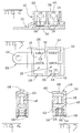
- branch connector 2 for electrical connection to conducting wires 4.
- the branch connector 2 comprises a base member 6 and cover members 8.
- the base member 6 comprising a stamped and formed sheet metal conductor 10, an insulative housing 12, and sealing means 14.
- the conductor 10 comprises a substantially flat interconnecting base portion 16, insulation displacement contact portions 18 in parallel and juxtaposed manner upstanding from the interconnecting portion 16, and an exterior contact portion 20 having a bolt or rivet hole 22.
- the insulation displacement contact (IDC) portions 18 comprise a pair of opposing upstanding IDC walls 24 comprising slots 26 for receiving the electrical conducting wire 4 and making electrical contact therewith.
- the housing 12 comprises compartments 28 having a base wall 30, and upstanding side walls 32, a back wall 34 and an opposing wire receiving front wall 36, whereby the walls 32, 34, 36 surround a pair of IDC contact portions 18 and extend past upper ends 38 thereof.
- the compartments 28 also comprise cover retention means in the form of window cutouts 40, and a V-shaped wire receiving slot 42 having a tapered profile 44.
- the cover member 8 comprising an insulative housing 46, having a wire receiving cavity 48, transversely intersected by IDC contact portion slots 50 extending from a mating face 52, and a single wire seal cylindrical receiving cavity 54 aligned and adjoined to the wire receiving cavity 48 and extending from a wire receiving face 56 of the cover member 8.
- the cover member 8 also has retention means 58 consisting of tapered projections cooperable with the windows 40 of the base member housing 12.
- the mating face 52 comprises an outer sealing surface 60 surrounding the IDC receiving slots 50, the contour of the sealing surface 60 being continuous and planar.
- the branch connector 2 is manufactured by first stamping and forming the branch conductor 10 from sheet metal and then placing it in a mould whereby the insulative housing 12 is overmoulded to the branch conductor 10.
- the sealing means 14 can then also be overmoulded over the conductor 10 and base 30 of the compartments 28 so as to provide a planar sealing surface on the floor of the compartments 28 that surrounds the IDC contact portions 18 and is biasable against the cover sealing surface 60.
- the in-moulding of the branch conductor 10 to the housing 12 and sealing floor 14, enables electrical connection between the exterior conducting portion 20 and the IDC portions 18 yet ensuring that the IDC contact portions 18 are completely sealed off from the exterior except for a cover receiving face 62 ( Figure 2) that is then sealed off by the cover member 8 as described hereinafter.
- the compartment walls 32, 34, 36 extent past ends 38 of the IDC contact portions 18 which provides, among other things, protection thereof against damage during handling and assembly.
- a single wire seal 64 ( Figure 5) is first inserted into the seal receiving cavity 54 of the cover member 8, the conducting wire 4 is then inserted through a wire receiving cavity 66 of the seal 64 and into the wire receiving cavity 48 until it abuts an end wall 68 of the cover 8.
- the single wire seal 64 has sealing ribs on its outer and inner surfaces that are resiliently biased against the seal receiving cavity 54 and the wire 4 such that the wire is sealed with respect to the cover member 8 except for the mating face 52.
- the cover member 8 can than be pressed into the compartments 28 whereby the IDC contacts 24 are inserted into the receiving slots 50 such that the wire 4 is forced into the IDC slots 26 that cut through the insulation and make electrical contact with conducting strands of the wires 4.
- the exterior portion of the wire 4 adjacent the seal 64 is inserted into the V-shaped slot 42 whereby the wire 4 is squeezed between opposing edges 70, 72 thereof, the tapered profile 44 creating acute angled edges 70, 72 for effectively digging into the wire 4 in order to act as a retention means.
- the tapered profile 44 is such that the smallest width between edges 70, 72 is adjacent the inner side of the compartment 28 so as to effectively retain the wire from an external pulling force therealong.
- the sealing surface 60 thereof abuts the sealing floor 14 whereby the cover member 8 can then be further inserted by resiliently biasing the sealing surface 60 thereagainst until the projections 58 of the cover engage in the windows 40 of the compartments 28.
- the cover member 8 is thus securely latched to the compartments 28 and resiliently biased against the sealing floor 14, the IDC connection between wire 4 and contact portion 18 thus being completely sealed off from the exterior.
- the sealing means 14 may not be moulded over the whole floor of the compartment but only at a position adjacent the sealing surface 60 of the cover, or the sealing means 14 could be provided as a loose piece or even moulded to the sealing surface 60 of the cover member 8.
- the connector 2 may also not be a branch connector having a common interconnecting portion 16, but may have separate terminals each having exterior contact portions (20), the exterior contact portions 20 could be of any form known in the prior art.
- the branch connection is a two position branch connector but of course if need be, a large plurality of IDC contacting portions 18 can be provided by simply extending the interconnecting portion 16 and moulding more compartments thereto. It could even be imagined to provide sealing means along the inner surfaces of the compartment walls 32, 34, 36 surrounding the IDC contact portions 18.
- the base member 6 of the connector can be assembled to a structure, for example the body work of an automobile, and the conducting wires 4 can be very rapidly and simply electrically connected thereto at a later assembly stage.
- the provision of a reliable sealed connector without requiring the use of sealing gels or greases whereby insulation displacement technology is used.
- the wire 4 can be assembled to the cover member 8 and provisionally held thereto during preparation of the harness in an automated process at the harness making location, the seal 64 provisionally holding the wire to the cover member 8.
- the wire 4 can then be electrically connected to a branch connector, for example, in a very simple manner by merely pushing the cover member 8 into the compartments 28.
- the cost effective and simple sealed IDC branch connector with stamped and formed terminals 18, 16 that can comprise a large plurality of terminals as desired.
Landscapes
- Chemical & Material Sciences (AREA)
- Dispersion Chemistry (AREA)
- Connector Housings Or Holding Contact Members (AREA)
- Details Of Connecting Devices For Male And Female Coupling (AREA)
- Connections By Means Of Piercing Elements, Nuts, Or Screws (AREA)
Applications Claiming Priority (2)
| Application Number | Priority Date | Filing Date | Title |
|---|---|---|---|
| GB9313281 | 1993-06-28 | ||
| GB939313281A GB9313281D0 (en) | 1993-06-28 | 1993-06-28 | Sealed insulation displacement connector |
Publications (3)
| Publication Number | Publication Date |
|---|---|
| EP0631344A2 true EP0631344A2 (fr) | 1994-12-28 |
| EP0631344A3 EP0631344A3 (fr) | 1996-02-14 |
| EP0631344B1 EP0631344B1 (fr) | 1998-08-12 |
Family
ID=10737903
Family Applications (1)
| Application Number | Title | Priority Date | Filing Date |
|---|---|---|---|
| EP94109915A Expired - Lifetime EP0631344B1 (fr) | 1993-06-28 | 1994-06-27 | Connecteur étanche à déplacement d'isolant |
Country Status (7)
| Country | Link |
|---|---|
| EP (1) | EP0631344B1 (fr) |
| JP (1) | JPH0722079A (fr) |
| KR (1) | KR950002117A (fr) |
| CN (1) | CN1038083C (fr) |
| BR (1) | BR9402526A (fr) |
| DE (1) | DE69412376T2 (fr) |
| GB (1) | GB9313281D0 (fr) |
Cited By (18)
| Publication number | Priority date | Publication date | Assignee | Title |
|---|---|---|---|---|
| EP0738025A1 (fr) * | 1995-04-13 | 1996-10-16 | Molex Incorporated | Assemblage d'un connecteur électrique étanche |
| EP0895309A2 (fr) * | 1997-08-01 | 1999-02-03 | TELEFUNKEN electronic GmbH | Réceptacle pour plaque à circuits imprimés avec des bornes électriques et dispositif de connexion auto dénudant |
| DE19741603A1 (de) * | 1997-09-20 | 1999-03-25 | Volkswagen Ag | Elektrische Kontakteinrichtung sowie Verfahren zur Schneidkontaktherstellung |
| DE19816216A1 (de) * | 1998-04-09 | 1999-10-21 | Siemens Ag | Dichter elektrischer Verbinder und Verbindungssystem |
| US6196873B1 (en) | 1998-06-10 | 2001-03-06 | Yazaki Corporation | Waterproof connector |
| US6203348B1 (en) | 1998-07-06 | 2001-03-20 | Yazaki Corporation | Waterproof connector and waterproof rubber member |
| US6343952B1 (en) | 1998-07-09 | 2002-02-05 | Yazaki Corporation | Waterproof connector |
| GB2368197A (en) * | 2000-10-11 | 2002-04-24 | Channell Ltd | Cable clamp for idc terminal connector |
| US6398585B1 (en) | 1998-03-31 | 2002-06-04 | Yazaki Corporation | Waterproof connector and waterproofing method |
| US6494740B1 (en) | 1998-03-31 | 2002-12-17 | Yazaki Corporation | Waterproof connector and fabrication method thereof |
| EP1280236A1 (fr) * | 2001-07-19 | 2003-01-29 | Nexans | Dispositif pour connecter un appareil électrique sur une ligne d'alimentation |
| US6514102B1 (en) | 1998-03-31 | 2003-02-04 | Yazaki Corporation | Waterproof connector and waterproofing method |
| US6527574B1 (en) | 1998-03-31 | 2003-03-04 | Yazaki Corporation | Waterproof connector and method for assembling same |
| DE102011106853A1 (de) * | 2011-07-05 | 2013-01-10 | Wago Verwaltungsgesellschaft Mbh | Einbau-Steckverbinder |
| EP3657604A1 (fr) * | 2018-11-26 | 2020-05-27 | TE Connectivity Germany GmbH | Ensemble de terminaison de câble avec des lames de coupe électriquement isolantes |
| EP3739688A1 (fr) * | 2019-05-15 | 2020-11-18 | TE Connectivity Nederland B.V. | Connecteur de câble électrique |
| DE102021134576A1 (de) | 2021-12-23 | 2023-06-29 | iwis smart connect GmbH | IDC-Schneidkontakt |
| DE102021134570A1 (de) | 2021-12-23 | 2023-06-29 | iwis smart connect GmbH | Abgedichtete Steckverbindereinheit |
Families Citing this family (5)
| Publication number | Priority date | Publication date | Assignee | Title |
|---|---|---|---|---|
| JP3530024B2 (ja) | 1998-03-11 | 2004-05-24 | 矢崎総業株式会社 | 防水コネクタ及び該防水コネクタの組付方法 |
| JP3500065B2 (ja) | 1998-06-25 | 2004-02-23 | 矢崎総業株式会社 | 防水コネクタ |
| KR100857035B1 (ko) * | 2006-12-20 | 2008-09-08 | 대은전자 주식회사 | 스냅형 케이블체결방식의 아이디씨 블럭 |
| JP5216644B2 (ja) * | 2009-03-17 | 2013-06-19 | 矢崎総業株式会社 | ジョイントコネクタ |
| JP6598810B2 (ja) * | 2017-03-22 | 2019-10-30 | 京セラ株式会社 | コネクタ |
Citations (2)
| Publication number | Priority date | Publication date | Assignee | Title |
|---|---|---|---|---|
| EP0095307A1 (fr) * | 1982-05-24 | 1983-11-30 | Minnesota Mining And Manufacturing Company | Connecteur électrique pour fils |
| WO1993007654A1 (fr) * | 1991-10-11 | 1993-04-15 | Raychem Corporation | Bloc de connexion utilise en telecommunications |
Family Cites Families (5)
| Publication number | Priority date | Publication date | Assignee | Title |
|---|---|---|---|---|
| US4697862A (en) * | 1985-05-29 | 1987-10-06 | E. I. Du Pont De Nemours And Company | Insulation displacement coaxial cable termination and method |
| CA1298369C (fr) * | 1987-11-06 | 1992-03-31 | George Debortoli | Connecteur electrique a piece d'extremite en pointe |
| US4978314A (en) * | 1988-11-24 | 1990-12-18 | Yazaki Corporation | Waterproof press-connecting connector |
| US4954098A (en) * | 1989-11-01 | 1990-09-04 | Minnesota Mining And Manufacturing Company | Sealed insulation displacement connector |
| GB9026529D0 (en) * | 1990-12-06 | 1991-01-23 | Amp Holland | An electrical wire connector and an electrical terminal therefor |
-
1993
- 1993-06-28 GB GB939313281A patent/GB9313281D0/en active Pending
-
1994
- 1994-06-22 KR KR1019940014273A patent/KR950002117A/ko not_active Application Discontinuation
- 1994-06-23 BR BR9402526A patent/BR9402526A/pt not_active Application Discontinuation
- 1994-06-27 CN CN94107657A patent/CN1038083C/zh not_active Expired - Fee Related
- 1994-06-27 EP EP94109915A patent/EP0631344B1/fr not_active Expired - Lifetime
- 1994-06-27 DE DE69412376T patent/DE69412376T2/de not_active Expired - Fee Related
- 1994-06-28 JP JP6168834A patent/JPH0722079A/ja active Pending
Patent Citations (2)
| Publication number | Priority date | Publication date | Assignee | Title |
|---|---|---|---|---|
| EP0095307A1 (fr) * | 1982-05-24 | 1983-11-30 | Minnesota Mining And Manufacturing Company | Connecteur électrique pour fils |
| WO1993007654A1 (fr) * | 1991-10-11 | 1993-04-15 | Raychem Corporation | Bloc de connexion utilise en telecommunications |
Cited By (27)
| Publication number | Priority date | Publication date | Assignee | Title |
|---|---|---|---|---|
| EP0738025A1 (fr) * | 1995-04-13 | 1996-10-16 | Molex Incorporated | Assemblage d'un connecteur électrique étanche |
| EP0895309A2 (fr) * | 1997-08-01 | 1999-02-03 | TELEFUNKEN electronic GmbH | Réceptacle pour plaque à circuits imprimés avec des bornes électriques et dispositif de connexion auto dénudant |
| EP0895309A3 (fr) * | 1997-08-01 | 2000-04-12 | TELEFUNKEN electronic GmbH | Réceptacle pour plaque à circuits imprimés avec des bornes électriques et dispositif de connexion auto dénudant |
| US6196863B1 (en) | 1997-09-20 | 2001-03-06 | Volkswagen Ag | Electrical connection arrangement and method for making electrical connection |
| DE19741603A1 (de) * | 1997-09-20 | 1999-03-25 | Volkswagen Ag | Elektrische Kontakteinrichtung sowie Verfahren zur Schneidkontaktherstellung |
| US6494740B1 (en) | 1998-03-31 | 2002-12-17 | Yazaki Corporation | Waterproof connector and fabrication method thereof |
| US6514102B1 (en) | 1998-03-31 | 2003-02-04 | Yazaki Corporation | Waterproof connector and waterproofing method |
| US6398585B1 (en) | 1998-03-31 | 2002-06-04 | Yazaki Corporation | Waterproof connector and waterproofing method |
| US6527574B1 (en) | 1998-03-31 | 2003-03-04 | Yazaki Corporation | Waterproof connector and method for assembling same |
| DE19816216C2 (de) * | 1998-04-09 | 2001-06-07 | Siemens Ag | Elektrischer Stecker und Steckverbindung |
| DE19816216A1 (de) * | 1998-04-09 | 1999-10-21 | Siemens Ag | Dichter elektrischer Verbinder und Verbindungssystem |
| US6196873B1 (en) | 1998-06-10 | 2001-03-06 | Yazaki Corporation | Waterproof connector |
| US6203348B1 (en) | 1998-07-06 | 2001-03-20 | Yazaki Corporation | Waterproof connector and waterproof rubber member |
| US6343952B1 (en) | 1998-07-09 | 2002-02-05 | Yazaki Corporation | Waterproof connector |
| GB2368197B (en) * | 2000-10-11 | 2003-12-03 | Channell Ltd | Electrical connector and strain relief therefor |
| GB2368197A (en) * | 2000-10-11 | 2002-04-24 | Channell Ltd | Cable clamp for idc terminal connector |
| AU776325B2 (en) * | 2000-10-11 | 2004-09-02 | Channell Limited | Electrical connector |
| EP1280236A1 (fr) * | 2001-07-19 | 2003-01-29 | Nexans | Dispositif pour connecter un appareil électrique sur une ligne d'alimentation |
| DE102011106853A1 (de) * | 2011-07-05 | 2013-01-10 | Wago Verwaltungsgesellschaft Mbh | Einbau-Steckverbinder |
| US8714992B2 (en) | 2011-07-05 | 2014-05-06 | Wago Verwaltungsgesellschaft Mbh | Receptacle connector having a base part with sealing lips fitted in a housing wall |
| EP3657604A1 (fr) * | 2018-11-26 | 2020-05-27 | TE Connectivity Germany GmbH | Ensemble de terminaison de câble avec des lames de coupe électriquement isolantes |
| WO2020109260A1 (fr) * | 2018-11-26 | 2020-06-04 | Te Connectivity Germany Gmbh | Ensemble de terminaison de câble à lames de coupe électriquement isolantes |
| US12057685B2 (en) | 2018-11-26 | 2024-08-06 | Te Connectivity Germany Gmbh | Cable terminating assembly with electrically insulating cutting blades |
| EP3739688A1 (fr) * | 2019-05-15 | 2020-11-18 | TE Connectivity Nederland B.V. | Connecteur de câble électrique |
| US11158960B2 (en) * | 2019-05-15 | 2021-10-26 | Te Connectivity Nederland Bv | Electric wire connector |
| DE102021134576A1 (de) | 2021-12-23 | 2023-06-29 | iwis smart connect GmbH | IDC-Schneidkontakt |
| DE102021134570A1 (de) | 2021-12-23 | 2023-06-29 | iwis smart connect GmbH | Abgedichtete Steckverbindereinheit |
Also Published As
| Publication number | Publication date |
|---|---|
| JPH0722079A (ja) | 1995-01-24 |
| BR9402526A (pt) | 1995-03-14 |
| DE69412376D1 (de) | 1998-09-17 |
| CN1038083C (zh) | 1998-04-15 |
| DE69412376T2 (de) | 1999-01-28 |
| GB9313281D0 (en) | 1993-08-11 |
| EP0631344A3 (fr) | 1996-02-14 |
| KR950002117A (ko) | 1995-01-04 |
| EP0631344B1 (fr) | 1998-08-12 |
| CN1099511A (zh) | 1995-03-01 |
Similar Documents
| Publication | Publication Date | Title |
|---|---|---|
| EP0631344B1 (fr) | Connecteur étanche à déplacement d'isolant | |
| US5980335A (en) | Electrical terminal | |
| US5380220A (en) | Connector | |
| CA2011936C (fr) | Connecteur de cables | |
| US6068505A (en) | Electrical contact for flexible flat cable | |
| EP0795930B1 (fr) | Contact électrique recevant une broche avec une force de contact élevée | |
| US5458502A (en) | IDC Terminal with back-up spring | |
| US6677531B2 (en) | Waterproof structure for terminal | |
| US5611716A (en) | Electrical contact having improved secondary locking surfaces | |
| KR960002133B1 (ko) | 통합 몰드된 케이블 종단 조립체 및 그 제조방법 | |
| MXPA05006361A (es) | Conector electrico de cable flexible. | |
| US5669778A (en) | IDC branch connector for large range of wire sizes | |
| US4315663A (en) | Multiple position brush connector | |
| CA2327868C (fr) | Interconnexion electrique a alignement automatique | |
| US5554046A (en) | Solderless terminal | |
| US5697813A (en) | Connection terminal | |
| JPS6276176A (ja) | 電気コネクタ組立体 | |
| EP0600402B1 (fr) | Connecteur électrique avec retenue de contact améliorée | |
| JPH11121108A (ja) | 回路基板用電気コネクタ | |
| EP1478052B1 (fr) | Terminal à contact à pression de denudage de gaines | |
| JP2001155792A (ja) | 圧接ジョイント端子及びコネクタ | |
| US6296512B1 (en) | Press-connecting terminal | |
| US6283784B1 (en) | Press-contact terminal fitting | |
| US6270373B1 (en) | Connector with contact | |
| WO1998047201A1 (fr) | Connecteur autodenudant |
Legal Events
| Date | Code | Title | Description |
|---|---|---|---|
| PUAI | Public reference made under article 153(3) epc to a published international application that has entered the european phase |
Free format text: ORIGINAL CODE: 0009012 |
|
| AK | Designated contracting states |
Kind code of ref document: A2 Designated state(s): DE ES FR GB IT SE |
|
| PUAL | Search report despatched |
Free format text: ORIGINAL CODE: 0009013 |
|
| AK | Designated contracting states |
Kind code of ref document: A3 Designated state(s): DE ES FR GB IT SE |
|
| 17P | Request for examination filed |
Effective date: 19960311 |
|
| 17Q | First examination report despatched |
Effective date: 19970507 |
|
| GRAG | Despatch of communication of intention to grant |
Free format text: ORIGINAL CODE: EPIDOS AGRA |
|
| GRAG | Despatch of communication of intention to grant |
Free format text: ORIGINAL CODE: EPIDOS AGRA |
|
| GRAH | Despatch of communication of intention to grant a patent |
Free format text: ORIGINAL CODE: EPIDOS IGRA |
|
| GRAH | Despatch of communication of intention to grant a patent |
Free format text: ORIGINAL CODE: EPIDOS IGRA |
|
| GRAA | (expected) grant |
Free format text: ORIGINAL CODE: 0009210 |
|
| AK | Designated contracting states |
Kind code of ref document: B1 Designated state(s): DE ES FR GB IT SE |
|
| PG25 | Lapsed in a contracting state [announced via postgrant information from national office to epo] |
Ref country code: IT Free format text: LAPSE BECAUSE OF FAILURE TO SUBMIT A TRANSLATION OF THE DESCRIPTION OR TO PAY THE FEE WITHIN THE PRE;WARNING: LAPSES OF ITALIAN PATENTS WITH EFFECTIVE DATE BEFORE 2007 MAY HAVE OCCURRED AT ANY TIME BEFORE 2007. THE CORRECT EFFECTIVE DATE MAY BE DIFFERENT FROM THE ONE RECORDED.SCRIBED TIME-LIMIT Effective date: 19980812 Ref country code: ES Free format text: THE PATENT HAS BEEN ANNULLED BY A DECISION OF A NATIONAL AUTHORITY Effective date: 19980812 |
|
| REF | Corresponds to: |
Ref document number: 69412376 Country of ref document: DE Date of ref document: 19980917 |
|
| ET | Fr: translation filed | ||
| PG25 | Lapsed in a contracting state [announced via postgrant information from national office to epo] |
Ref country code: SE Free format text: LAPSE BECAUSE OF FAILURE TO SUBMIT A TRANSLATION OF THE DESCRIPTION OR TO PAY THE FEE WITHIN THE PRESCRIBED TIME-LIMIT Effective date: 19981112 |
|
| PLBE | No opposition filed within time limit |
Free format text: ORIGINAL CODE: 0009261 |
|
| STAA | Information on the status of an ep patent application or granted ep patent |
Free format text: STATUS: NO OPPOSITION FILED WITHIN TIME LIMIT |
|
| 26N | No opposition filed | ||
| PGFP | Annual fee paid to national office [announced via postgrant information from national office to epo] |
Ref country code: GB Payment date: 20000502 Year of fee payment: 7 |
|
| PGFP | Annual fee paid to national office [announced via postgrant information from national office to epo] |
Ref country code: FR Payment date: 20000602 Year of fee payment: 7 |
|
| PG25 | Lapsed in a contracting state [announced via postgrant information from national office to epo] |
Ref country code: GB Free format text: LAPSE BECAUSE OF NON-PAYMENT OF DUE FEES Effective date: 20010627 |
|
| GBPC | Gb: european patent ceased through non-payment of renewal fee |
Effective date: 20010627 |
|
| PG25 | Lapsed in a contracting state [announced via postgrant information from national office to epo] |
Ref country code: FR Free format text: LAPSE BECAUSE OF NON-PAYMENT OF DUE FEES Effective date: 20020228 |
|
| PGFP | Annual fee paid to national office [announced via postgrant information from national office to epo] |
Ref country code: DE Payment date: 20020628 Year of fee payment: 9 |
|
| PG25 | Lapsed in a contracting state [announced via postgrant information from national office to epo] |
Ref country code: DE Free format text: LAPSE BECAUSE OF NON-PAYMENT OF DUE FEES Effective date: 20040101 |