EP0631050B1 - Pompe - Google Patents
Pompe Download PDFInfo
- Publication number
- EP0631050B1 EP0631050B1 EP94109835A EP94109835A EP0631050B1 EP 0631050 B1 EP0631050 B1 EP 0631050B1 EP 94109835 A EP94109835 A EP 94109835A EP 94109835 A EP94109835 A EP 94109835A EP 0631050 B1 EP0631050 B1 EP 0631050B1
- Authority
- EP
- European Patent Office
- Prior art keywords
- piston
- pump
- pump chamber
- chamber
- valve means
- Prior art date
- Legal status (The legal status is an assumption and is not a legal conclusion. Google has not performed a legal analysis and makes no representation as to the accuracy of the status listed.)
- Expired - Lifetime
Links
Images


Classifications
-
- F—MECHANICAL ENGINEERING; LIGHTING; HEATING; WEAPONS; BLASTING
- F04—POSITIVE - DISPLACEMENT MACHINES FOR LIQUIDS; PUMPS FOR LIQUIDS OR ELASTIC FLUIDS
- F04B—POSITIVE-DISPLACEMENT MACHINES FOR LIQUIDS; PUMPS
- F04B23/00—Pumping installations or systems
- F04B23/04—Combinations of two or more pumps
-
- F—MECHANICAL ENGINEERING; LIGHTING; HEATING; WEAPONS; BLASTING
- F04—POSITIVE - DISPLACEMENT MACHINES FOR LIQUIDS; PUMPS FOR LIQUIDS OR ELASTIC FLUIDS
- F04B—POSITIVE-DISPLACEMENT MACHINES FOR LIQUIDS; PUMPS
- F04B5/00—Machines or pumps with differential-surface pistons
- F04B5/02—Machines or pumps with differential-surface pistons with double-acting pistons
-
- B—PERFORMING OPERATIONS; TRANSPORTING
- B60—VEHICLES IN GENERAL
- B60T—VEHICLE BRAKE CONTROL SYSTEMS OR PARTS THEREOF; BRAKE CONTROL SYSTEMS OR PARTS THEREOF, IN GENERAL; ARRANGEMENT OF BRAKING ELEMENTS ON VEHICLES IN GENERAL; PORTABLE DEVICES FOR PREVENTING UNWANTED MOVEMENT OF VEHICLES; VEHICLE MODIFICATIONS TO FACILITATE COOLING OF BRAKES
- B60T8/00—Arrangements for adjusting wheel-braking force to meet varying vehicular or ground-surface conditions, e.g. limiting or varying distribution of braking force
- B60T8/32—Arrangements for adjusting wheel-braking force to meet varying vehicular or ground-surface conditions, e.g. limiting or varying distribution of braking force responsive to a speed condition, e.g. acceleration or deceleration
- B60T8/34—Arrangements for adjusting wheel-braking force to meet varying vehicular or ground-surface conditions, e.g. limiting or varying distribution of braking force responsive to a speed condition, e.g. acceleration or deceleration having a fluid pressure regulator responsive to a speed condition
- B60T8/40—Arrangements for adjusting wheel-braking force to meet varying vehicular or ground-surface conditions, e.g. limiting or varying distribution of braking force responsive to a speed condition, e.g. acceleration or deceleration having a fluid pressure regulator responsive to a speed condition comprising an additional fluid circuit including fluid pressurising means for modifying the pressure of the braking fluid, e.g. including wheel driven pumps for detecting a speed condition, or pumps which are controlled by means independent of the braking system
- B60T8/4031—Pump units characterised by their construction or mounting
-
- F—MECHANICAL ENGINEERING; LIGHTING; HEATING; WEAPONS; BLASTING
- F04—POSITIVE - DISPLACEMENT MACHINES FOR LIQUIDS; PUMPS FOR LIQUIDS OR ELASTIC FLUIDS
- F04B—POSITIVE-DISPLACEMENT MACHINES FOR LIQUIDS; PUMPS
- F04B23/00—Pumping installations or systems
- F04B23/04—Combinations of two or more pumps
- F04B23/06—Combinations of two or more pumps the pumps being all of reciprocating positive-displacement type
-
- F—MECHANICAL ENGINEERING; LIGHTING; HEATING; WEAPONS; BLASTING
- F04—POSITIVE - DISPLACEMENT MACHINES FOR LIQUIDS; PUMPS FOR LIQUIDS OR ELASTIC FLUIDS
- F04B—POSITIVE-DISPLACEMENT MACHINES FOR LIQUIDS; PUMPS
- F04B53/00—Component parts, details or accessories not provided for in, or of interest apart from, groups F04B1/00 - F04B23/00 or F04B39/00 - F04B47/00
- F04B53/10—Valves; Arrangement of valves
- F04B53/12—Valves; Arrangement of valves arranged in or on pistons
- F04B53/122—Valves; Arrangement of valves arranged in or on pistons the piston being free-floating, e.g. the valve being formed between the actuating rod and the piston
-
- F—MECHANICAL ENGINEERING; LIGHTING; HEATING; WEAPONS; BLASTING
- F04—POSITIVE - DISPLACEMENT MACHINES FOR LIQUIDS; PUMPS FOR LIQUIDS OR ELASTIC FLUIDS
- F04B—POSITIVE-DISPLACEMENT MACHINES FOR LIQUIDS; PUMPS
- F04B53/00—Component parts, details or accessories not provided for in, or of interest apart from, groups F04B1/00 - F04B23/00 or F04B39/00 - F04B47/00
- F04B53/10—Valves; Arrangement of valves
- F04B53/12—Valves; Arrangement of valves arranged in or on pistons
- F04B53/125—Reciprocating valves
- F04B53/126—Ball valves
Landscapes
- Engineering & Computer Science (AREA)
- Mechanical Engineering (AREA)
- General Engineering & Computer Science (AREA)
- Physics & Mathematics (AREA)
- Fluid Mechanics (AREA)
- Transportation (AREA)
- Details Of Reciprocating Pumps (AREA)
- Reciprocating Pumps (AREA)
Claims (12)
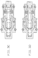
- Pompe (100 ; 600) munie d'un premier mécanisme de pompe et d'un second mécanisme de pompe comportant :un logement renfermant une première chambre de pompe (152 ; 660), une seconde chambre de pompe (170 ; 670), un orifice d'admission (110 ; 610) communiquant avec ladite première chambre de pompe (152 ; 660) et un orifice de refoulement (120 ; 614) communiquant avec ladite seconde chambre de pompe (170 ; 670) ;un premier moyen de soupape (164 ; 664) disposé dans un passage de communication (128 ; 630) entre ladite première chambre de pompe (152 ; 660) et ladite seconde chambre de pompe (170 ; 670) qui ouvre ledit passage de communication (128 ; 630) lorsque ladite seconde chambre de pompe (170 ; 670) est étendue et ferme ledit passage de communication (128 ; 630) lorsque ladite seconde chambre de pompe (170 ; 670) est comprimée ;un piston (126 ; 626) disposé pour être animé d'un mouvement de va et vient dans ledit logement, qui étend ladite seconde chambre de pompe (170 ; 670) lorsque ladite première chambre de pompe (152 ; 660) est comprimée, et qui comprime ladite seconde chambre de pompe (170 ; 670) lorsque ladite première chambre de pompe (152 ; 660) est étendue en conformité avec son mouvement ;un second moyen de soupape (146 ; 646) disposé autour dudit orifice d'admission (110 ; 610) dans ledit logement, qui s'ouvre de manière à permettre la circulation d'un fluide dans ladite première chambre de pompe (152 ; 660) lorsque ladite première chambre de pompe (152 ; 660) est étendue et se ferme de manière à éviter que le fluide présent dans ladite première chambre de pompe (152 ; 660) ne sorte de ladite première chambre de pompe (152 ; 660) lorsque ladite première chambre de pompe (152 ; 660) est comprimée, etun troisième moyen de soupape (188 ; 672) disposé autour dudit orifice de refoulement (120 ; 614) dans ledit logement, qui s'ouvre de manière à refouler le fluide pressurisé de ladite seconde chambre de pompe (170 ; 670) lorsque ladite seconde chambre de pompe (170, 670) est comprimée et se ferme lorsque ladite seconde chambre de pompe (170 ; 670) est étendue.
- Pompe (100 ; 600) selon la revendication 1, dans laquelle ledit second moyen de soupape (146, 646) est disposé en coulissement dans ledit logement et est engagé dans ledit piston (126 ; 626), ledit second moyen de soupape (146 ; 646) coulisse en conformité avec le mouvement de va et vient dudit piston (146 ; 646), d'où l'ouverture et la fermeture de ladite première chambre de pompe (152 ; 660).
- Pompe (100 ; 600) selon la revendication 1 ou 2, dans laquelle ledit second moyen de soupape (146, 646) est en contact avec la première partie d'engagement (142 ; 642) dudit piston (126 ; 626) et coulisse dans ledit logement dans une certaine direction lorsque ledit piston (126 ; 626) se déplace dans un sens, et est en contact avec la seconde partie d'engagement (140 ; 640) dudit piston (126 ; 626) et coulisse dans le sens inverse lorsque ledit piston (126 ; 626) se déplace dans l'autre sens, et un interstice est respectivement formé entre ledit second moyen de soupape (146 ; 646) et ladite première partie d'engagement (142 ; 642) dudit piston (126 ; 626) lorsque ledit second moyen de soupape (146 ; 646) est en contact avec l'autre partie d'engagement (140 ; 640) dudit piston (126 ; 626).
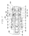
- Pompe (600) selon la revendication 3, dans laquelle lesdites première et seconde parties d'engagement (640 ; 642) sont constituées des deux parois latérales formées par une rainures annulaire (638) sur la surface périphérique dudit piston (626), et ledit second moyen de soupape (646) est disposé autour de la partie à rainure (638) dudit piston (626) et présente une partie à encoche (658) qui est en contact avec ladite première partie d'engagement (640) dudit piston (626).
- Pompe (100 ; 600) selon la revendication 1, dans laquelle ledit piston comporte un second piston (146 ; 646) qui est engagé dans ledit piston (126 ; 626) et est animé d'un mouvement de va et vient en conformité avec ledit mouvement de va et vient dudit piston (126 ; 626), le volume dans ladite première chambre de pompe (152 ; 660) est comprimé lorsque ledit second moyen de soupape (146, 646) ferme et est étendu lorsque ledit second moyen de soupape (146 ; 646) s'ouvre en conformité avec son mouvement de va et vient.
- Pompe (100 ; 600) selon la revendication 5, dans laquelle ledit second moyen de soupape (146 ; 646) est engagé dans ledit piston (126 ; 626) et coulisse dans ledit logement en conformité avec ledit mouvement de va et vient dudit piston (126 ; 626) , d'où l'ouverture et la fermeture de ladite première chambre de pompe, et ledit second moyen de soupape (146 ; 646) coulisse de manière à comprimer ledit volume dans ladite première chambre de pompe alors que ledit second piston après ledit second moyen de soupape (146 ; 646) ferme la communication entre la première chambre de pompe (152 ; 660) et ledit orifice d'admission (110 ; 610).
- Pompe (100 ; 600) selon l'une quelconque des revendications 1 à 6, dans laquelle ledit premier moyen de soupape et ledit troisième moyen de soupape comportent respectivement un élément de clapet (164, 168, 664, 672) et un moyen d'application de pression (166, 190, 666, 674) pour appliquer une pression audit élément de clapet (164, 168, 664, 672) dans un sens tel que ladite seconde chambre de pompe (170 ; 670) est fermée, la pression du fluide dans lesdites première et seconde chambres de pompe (152, 170 ; 660, 670) agit sur ledit élément de clapet (164 ; 664) dudit premier moyen de soupape pour résister audit moyen d'application de pression (166 ; 666) du premier moyen de soupape, et la pression du fluide dans ladite seconde chambre de pompe (170 ; 672) agit sur ledit élément de clapet (188 ; 670) du troisième moyen de soupape pour résister audit moyen d'application de pression (190 ; 674) dudit troisième moyen de soupape.
- Pompe (600) selon l'une quelconque des revendications 1 à 7, dans laquelle ledit troisième moyen de soupape (674) est disposé dans une direction perpendiculaire au déplacement dudit piston (626).
- Pompe (600) selon la revendication 8, dans laquelle ledit troisième moyen de soupape comporte un élément de clapet (671) et un moyen d'application de pression (674) afin d'appliquer une pression audit élément de clapet (671) dans une direction telle que ladite seconde chambre de pompe (670) est fermée, et ledit moyen d'application de pression (674) comporte une partie d'engagement (674b) engagée dans une paroi extérieure de ladite seconde chambre de pompe (670) et une partie mobile (674a) pour appliquer une pression audit élément de clapet (671) comme point de levier avec ladite partie d'engagement (674b).
- Pompe (600) selon la revendication 9, dans laquelle ledit moyen d'application de pression (674) est un matériau en forme d'anneau le long de la surface de ladite paroi extérieure de ladite seconde chambre de pompe (670), et une extrémité dudit matériau en anneau agit sur ledit élément de clapet (671) et une autre extrémité est engagée dans ladite paroi extérieure (676).
- Pompe (600) selon l'une quelconque des revendications 1 à 10, ledit passage de communication (630) entre ladite première chambre de pompe (660) et ladite seconde chambre de pompe (670) est formé à l'intérieur dudit piston (626), et ledit premier moyen de soupape (662) est disposé à l'intérieur dudit piston (626).
- Pompe (600) selon la revendication 11, dans laquelle une cavité (628) est formée dans ledit passage de communication (630) de manière à déboucher sur le côté de ladite seconde chambre de pompe (670), ledit premier moyen de soupape (662) est disposé dans ladite cavité (628), un matériau de maintien (656) pour supporter ledit moyen d'application de pression (666) dudit premier moyen de soupape (662) est fixé audit piston (626) de manière à recouvrir l'ouverture de ladite cavité (628).
Applications Claiming Priority (4)
| Application Number | Priority Date | Filing Date | Title |
|---|---|---|---|
| JP155368/93 | 1993-06-25 | ||
| JP15536893A JP3278982B2 (ja) | 1993-06-25 | 1993-06-25 | ポンプ |
| JP68640/94 | 1994-04-06 | ||
| JP06068640A JP3097726B2 (ja) | 1994-04-06 | 1994-04-06 | ポンプ |
Publications (2)
| Publication Number | Publication Date |
|---|---|
| EP0631050A1 EP0631050A1 (fr) | 1994-12-28 |
| EP0631050B1 true EP0631050B1 (fr) | 1997-12-17 |
Family
ID=26409839
Family Applications (1)
| Application Number | Title | Priority Date | Filing Date |
|---|---|---|---|
| EP94109835A Expired - Lifetime EP0631050B1 (fr) | 1993-06-25 | 1994-06-24 | Pompe |
Country Status (4)
| Country | Link |
|---|---|
| US (1) | US5577896A (fr) |
| EP (1) | EP0631050B1 (fr) |
| KR (1) | KR100226037B1 (fr) |
| DE (1) | DE69407348T2 (fr) |
Cited By (7)
| Publication number | Priority date | Publication date | Assignee | Title |
|---|---|---|---|---|
| GB2295651A (en) * | 1994-12-01 | 1996-06-05 | Bosch Gmbh Robert | Reciprocating pump |
| WO1999025978A1 (fr) | 1997-11-14 | 1999-05-27 | Continental Teves Ag & Co. Ohg | Pompe a piston |
| WO1999042725A2 (fr) | 1998-02-17 | 1999-08-26 | Continental Teves Ag & Co. Ohg | Pompe a piston |
| DE19937893A1 (de) * | 1999-08-16 | 2001-02-22 | Continental Teves Ag & Co Ohg | Kolbenpumpe |
| DE19938573A1 (de) * | 1999-08-17 | 2001-02-22 | Continental Teves Ag & Co Ohg | Kolbenpumpe |
| DE10115856C1 (de) * | 2001-03-30 | 2002-08-08 | Bosch Gmbh Robert | Hochdruck-Kraftstoffpumpe für eine direkteinspritzende Brennkraftmaschine, Kraftstoffsystem für eine direkteinspritzende Brennkraftmaschine, sowie direkteinspritzende Brennkraftmaschine |
| US6648614B1 (en) | 1999-06-19 | 2003-11-18 | Continental Teves Ag & Co. Ohg | Piston pump |
Families Citing this family (23)
| Publication number | Priority date | Publication date | Assignee | Title |
|---|---|---|---|---|
| WO1998006971A1 (fr) * | 1996-08-04 | 1998-02-19 | J. Lorch Gesellschaft & Co., Kg_Gesellschaft Für Maschinen Und Einrichtungen | Dispositif d'amenee par dose d'une quantite minimale de liquide |
| CN1089868C (zh) * | 1996-09-19 | 2002-08-28 | 罗伯特·博施有限公司 | 活塞泵 |
| EP0932760B1 (fr) * | 1997-07-30 | 2005-01-26 | Robert Bosch Gmbh | Dispositif antiperte pour un piston d'une pompe a pistons radiaux |
| DE19820136A1 (de) * | 1998-02-17 | 1999-08-19 | Itt Mfg Enterprises Inc | Kolbenpumpe |
| DE19902018A1 (de) * | 1999-01-20 | 2000-07-27 | Bosch Gmbh Robert | Kolbenpumpe |
| JP3314186B1 (ja) * | 2001-08-27 | 2002-08-12 | 一誠 生田 | 流体の吸引吐出装置 |
| JP4073313B2 (ja) * | 2001-04-27 | 2008-04-09 | ハイドロシジョン・インコーポレーテッド | 医療及び外科手術用ポンピング及び注入装置用の高圧ポンピングカートリッジ |
| US20040258547A1 (en) * | 2003-04-02 | 2004-12-23 | Kurt Burger | Pump piston and/or elements sealing the pump piston, in particular a sealing ring of elastomeric material, and a device and method for coating an object of elastomeric material |
| JP4143841B2 (ja) * | 2003-09-18 | 2008-09-03 | 株式会社アドヴィックス | ピストンポンプ |
| US7785085B2 (en) * | 2003-10-03 | 2010-08-31 | Advics Co., Ltd. | Piston pump |
| US7246551B2 (en) * | 2004-07-09 | 2007-07-24 | Protedyne Corporation | Liquid handling device with surface features at a seal |
| DE102004035453A1 (de) * | 2004-07-22 | 2006-02-16 | Robert Bosch Gmbh | Kolbenpumpe mit verbesserter Druckaufbaudynamik |
| DE102004037140A1 (de) * | 2004-07-30 | 2006-03-23 | Robert Bosch Gmbh | Kolbenpumpe mit verbessertem Wirkungsgrad |
| JP4857731B2 (ja) * | 2005-11-24 | 2012-01-18 | 株式会社アドヴィックス | 車両用ブレーキ装置 |
| JP4962044B2 (ja) * | 2007-02-27 | 2012-06-27 | 株式会社アドヴィックス | ピストンポンプ |
| JP5034705B2 (ja) * | 2007-06-18 | 2012-09-26 | 株式会社アドヴィックス | ピストンポンプ |
| JP5223719B2 (ja) * | 2009-02-18 | 2013-06-26 | 株式会社アドヴィックス | ピストンポンプ |
| DE102010040170A1 (de) * | 2010-09-02 | 2012-03-08 | Robert Bosch Gmbh | Kolbenpumpe zur Förderung von Fluiden und zugehörige Fahrzeugbremsanlage |
| CN102837744B (zh) * | 2012-09-19 | 2016-03-23 | 天津市恒信精密机械有限公司 | 无间隙密封液压换向装置 |
| CN102862613B (zh) * | 2012-09-19 | 2016-03-23 | 天津市恒信精密机械有限公司 | 一种驾驶室翻转无间隙密封举升泵 |
| DE102014013665B4 (de) * | 2014-09-16 | 2022-05-19 | Thomas Magnete Gmbh | Pumpenbaukastensystem für eine elektromagnetisch betätigte Hubkolbenpumpe |
| EP3374637B1 (fr) | 2015-11-11 | 2021-03-17 | Graco Minnesota Inc. | Cage à bille à trajectoires d'écoulement dirigés pour une pompe à billes |
| US11572876B2 (en) | 2017-08-30 | 2023-02-07 | Graco Minnesota Inc. | Pump piston |
Family Cites Families (13)
| Publication number | Priority date | Publication date | Assignee | Title |
|---|---|---|---|---|
| US176330A (en) * | 1876-04-18 | Improvement in pumps | ||
| US759514A (en) * | 1901-04-02 | 1904-05-10 | Hartwig A Cohen | Combined valve and packing. |
| US898659A (en) * | 1907-08-22 | 1908-09-15 | Theodore Kolischer | Compressor. |
| US1653562A (en) * | 1924-01-04 | 1927-12-20 | Grimley William | Syringe or sprayer |
| DE975469C (de) * | 1952-06-04 | 1961-12-07 | Mueller & Co Schwelmer Eisen | Pumpenkolben mit eingebautem Fluessigkeitsventil |
| JPS4892903A (fr) * | 1972-03-11 | 1973-12-01 | ||
| AU533188B2 (en) * | 1979-01-25 | 1983-11-10 | Macnaught Pty Limited | Grease gun |
| JPS60198382A (ja) * | 1984-03-19 | 1985-10-07 | Toshiba Mach Co Ltd | ピストンポンプ |
| JPS60198383A (ja) * | 1984-03-19 | 1985-10-07 | Toshiba Mach Co Ltd | ピストンポンプ |
| DE3907969A1 (de) * | 1989-03-11 | 1990-09-13 | Bosch Gmbh Robert | Hydraulische hochdruckpumpe fuer eine bremsanlage eines fahrzeugs |
| DE4107979C2 (de) * | 1991-03-13 | 1998-07-09 | Bosch Gmbh Robert | Hydraulische Hochdruckpumpe für Kraftfahrzeug-Bremsanlagen |
| JP2572034Y2 (ja) * | 1992-02-10 | 1998-05-20 | 株式会社ユニシアジェックス | ポンプ構造 |
| JP2759861B2 (ja) * | 1992-10-02 | 1998-05-28 | 日清紡績株式会社 | 液圧ポンプ |
-
1994
- 1994-06-24 DE DE69407348T patent/DE69407348T2/de not_active Expired - Lifetime
- 1994-06-24 EP EP94109835A patent/EP0631050B1/fr not_active Expired - Lifetime
- 1994-06-24 US US08/265,110 patent/US5577896A/en not_active Expired - Lifetime
- 1994-06-25 KR KR1019940014733A patent/KR100226037B1/ko not_active IP Right Cessation
Cited By (10)
| Publication number | Priority date | Publication date | Assignee | Title |
|---|---|---|---|---|
| GB2295651A (en) * | 1994-12-01 | 1996-06-05 | Bosch Gmbh Robert | Reciprocating pump |
| GB2295651B (en) * | 1994-12-01 | 1997-03-12 | Bosch Gmbh Robert | Reciprocating pumps |
| WO1999025978A1 (fr) | 1997-11-14 | 1999-05-27 | Continental Teves Ag & Co. Ohg | Pompe a piston |
| US6497562B1 (en) | 1997-11-14 | 2002-12-24 | Continental Teves Ag & Co., Ohg | Piston pump |
| US6705846B2 (en) | 1997-11-14 | 2004-03-16 | Continental Teves Ag & Co. Ohg | Piston pump |
| WO1999042725A2 (fr) | 1998-02-17 | 1999-08-26 | Continental Teves Ag & Co. Ohg | Pompe a piston |
| US6648614B1 (en) | 1999-06-19 | 2003-11-18 | Continental Teves Ag & Co. Ohg | Piston pump |
| DE19937893A1 (de) * | 1999-08-16 | 2001-02-22 | Continental Teves Ag & Co Ohg | Kolbenpumpe |
| DE19938573A1 (de) * | 1999-08-17 | 2001-02-22 | Continental Teves Ag & Co Ohg | Kolbenpumpe |
| DE10115856C1 (de) * | 2001-03-30 | 2002-08-08 | Bosch Gmbh Robert | Hochdruck-Kraftstoffpumpe für eine direkteinspritzende Brennkraftmaschine, Kraftstoffsystem für eine direkteinspritzende Brennkraftmaschine, sowie direkteinspritzende Brennkraftmaschine |
Also Published As
| Publication number | Publication date |
|---|---|
| DE69407348D1 (de) | 1998-01-29 |
| DE69407348T2 (de) | 1998-05-14 |
| EP0631050A1 (fr) | 1994-12-28 |
| KR100226037B1 (ko) | 1999-10-15 |
| KR950001095A (ko) | 1995-01-03 |
| US5577896A (en) | 1996-11-26 |
Similar Documents
| Publication | Publication Date | Title |
|---|---|---|
| EP0631050B1 (fr) | Pompe | |
| EP0908623B1 (fr) | Pistons pour compresseur à piston | |
| US5213482A (en) | Hydraulic radial-type piston pump | |
| US6312232B1 (en) | Method and apparatus for suppressing resonance | |
| CA1289598C (fr) | Pompe hydraulique a puisard et accumulateur integres | |
| US20060198740A1 (en) | Diaphragm pump | |
| JPH03502829A (ja) | 液圧ポンプ | |
| US7156626B2 (en) | Double side action type reciprocating compressor | |
| EP1625301B1 (fr) | Pompe a membrane | |
| US20050265862A1 (en) | Pump | |
| KR20000069788A (ko) | 피스톤 펌프 | |
| CN102052295B (zh) | 活塞泵的活塞装置 | |
| JP3278982B2 (ja) | ポンプ | |
| US3172369A (en) | Pump assembly | |
| CA1122479A (fr) | Pompe a pistons a double effet et debit variable | |
| JP3097726B2 (ja) | ポンプ | |
| EP0175206A1 (fr) | Machine à fluide | |
| JP2000345954A (ja) | ラジアルピストンポンプ | |
| US20030021709A1 (en) | Plunger pump device | |
| US20030025276A1 (en) | Shaft sealing devices, compressors comprising the shaft sealing devices, and methods for sealing a rotational shaft | |
| EP3096013B1 (fr) | Pompe a diaphragme | |
| US4906167A (en) | Inherently flushing piston rod for a reciprocating pump | |
| US20090047146A1 (en) | Eccentric Radial Piston Pump and Eccentric Radial Piston Motor | |
| KR100558701B1 (ko) | 용량가변형 사판식 압축기용 피스톤 | |
| EP0945618A2 (fr) | Soupape de contrÔle de déplacement utilisée dans un compresseur à capacité variable |
Legal Events
| Date | Code | Title | Description |
|---|---|---|---|
| PUAI | Public reference made under article 153(3) epc to a published international application that has entered the european phase |
Free format text: ORIGINAL CODE: 0009012 |
|
| AK | Designated contracting states |
Kind code of ref document: A1 Designated state(s): DE FR GB |
|
| 17P | Request for examination filed |
Effective date: 19950123 |
|
| 17Q | First examination report despatched |
Effective date: 19951227 |
|
| GRAG | Despatch of communication of intention to grant |
Free format text: ORIGINAL CODE: EPIDOS AGRA |
|
| GRAG | Despatch of communication of intention to grant |
Free format text: ORIGINAL CODE: EPIDOS AGRA |
|
| GRAH | Despatch of communication of intention to grant a patent |
Free format text: ORIGINAL CODE: EPIDOS IGRA |
|
| RAP1 | Party data changed (applicant data changed or rights of an application transferred) |
Owner name: DENSO CORPORATION |
|
| GRAH | Despatch of communication of intention to grant a patent |
Free format text: ORIGINAL CODE: EPIDOS IGRA |
|
| GRAA | (expected) grant |
Free format text: ORIGINAL CODE: 0009210 |
|
| AK | Designated contracting states |
Kind code of ref document: B1 Designated state(s): DE FR GB |
|
| REF | Corresponds to: |
Ref document number: 69407348 Country of ref document: DE Date of ref document: 19980129 |
|
| ET | Fr: translation filed | ||
| PLBE | No opposition filed within time limit |
Free format text: ORIGINAL CODE: 0009261 |
|
| STAA | Information on the status of an ep patent application or granted ep patent |
Free format text: STATUS: NO OPPOSITION FILED WITHIN TIME LIMIT |
|
| REG | Reference to a national code |
Ref country code: GB Ref legal event code: 746 Effective date: 19981029 |
|
| 26N | No opposition filed | ||
| REG | Reference to a national code |
Ref country code: GB Ref legal event code: IF02 |
|
| PGFP | Annual fee paid to national office [announced via postgrant information from national office to epo] |
Ref country code: DE Payment date: 20130619 Year of fee payment: 20 Ref country code: GB Payment date: 20130619 Year of fee payment: 20 |
|
| PGFP | Annual fee paid to national office [announced via postgrant information from national office to epo] |
Ref country code: FR Payment date: 20130624 Year of fee payment: 20 |
|
| REG | Reference to a national code |
Ref country code: DE Ref legal event code: R071 Ref document number: 69407348 Country of ref document: DE |
|
| REG | Reference to a national code |
Ref country code: GB Ref legal event code: PE20 Expiry date: 20140623 |
|
| PG25 | Lapsed in a contracting state [announced via postgrant information from national office to epo] |
Ref country code: GB Free format text: LAPSE BECAUSE OF EXPIRATION OF PROTECTION Effective date: 20140623 |
|
| PG25 | Lapsed in a contracting state [announced via postgrant information from national office to epo] |
Ref country code: DE Free format text: LAPSE BECAUSE OF EXPIRATION OF PROTECTION Effective date: 20140625 |