EP0630457B1 - Seal ring and joint - Google Patents
Seal ring and joint Download PDFInfo
- Publication number
- EP0630457B1 EP0630457B1 EP93905549A EP93905549A EP0630457B1 EP 0630457 B1 EP0630457 B1 EP 0630457B1 EP 93905549 A EP93905549 A EP 93905549A EP 93905549 A EP93905549 A EP 93905549A EP 0630457 B1 EP0630457 B1 EP 0630457B1
- Authority
- EP
- European Patent Office
- Prior art keywords
- spigot
- seal ring
- web
- seal
- sealing
- Prior art date
- Legal status (The legal status is an assumption and is not a legal conclusion. Google has not performed a legal analysis and makes no representation as to the accuracy of the status listed.)
- Expired - Lifetime
Links
- 238000007789 sealing Methods 0.000 claims abstract description 53
- 239000012530 fluid Substances 0.000 description 10
- 230000004048 modification Effects 0.000 description 4
- 238000012986 modification Methods 0.000 description 4
- 238000010079 rubber tapping Methods 0.000 description 3
- 229910001209 Low-carbon steel Inorganic materials 0.000 description 1
- 229910000831 Steel Inorganic materials 0.000 description 1
- 229910000963 austenitic stainless steel Inorganic materials 0.000 description 1
- 238000005452 bending Methods 0.000 description 1
- 230000000295 complement effect Effects 0.000 description 1
- 238000010276 construction Methods 0.000 description 1
- 230000000694 effects Effects 0.000 description 1
- 239000007769 metal material Substances 0.000 description 1
- 230000002093 peripheral effect Effects 0.000 description 1
- 230000035939 shock Effects 0.000 description 1
- 239000010959 steel Substances 0.000 description 1
Images



Classifications
-
- F—MECHANICAL ENGINEERING; LIGHTING; HEATING; WEAPONS; BLASTING
- F16—ENGINEERING ELEMENTS AND UNITS; GENERAL MEASURES FOR PRODUCING AND MAINTAINING EFFECTIVE FUNCTIONING OF MACHINES OR INSTALLATIONS; THERMAL INSULATION IN GENERAL
- F16L—PIPES; JOINTS OR FITTINGS FOR PIPES; SUPPORTS FOR PIPES, CABLES OR PROTECTIVE TUBING; MEANS FOR THERMAL INSULATION IN GENERAL
- F16L23/00—Flanged joints
- F16L23/16—Flanged joints characterised by the sealing means
- F16L23/167—Flanged joints characterised by the sealing means in connection with the appearance or detection of leaks
-
- F—MECHANICAL ENGINEERING; LIGHTING; HEATING; WEAPONS; BLASTING
- F16—ENGINEERING ELEMENTS AND UNITS; GENERAL MEASURES FOR PRODUCING AND MAINTAINING EFFECTIVE FUNCTIONING OF MACHINES OR INSTALLATIONS; THERMAL INSULATION IN GENERAL
- F16L—PIPES; JOINTS OR FITTINGS FOR PIPES; SUPPORTS FOR PIPES, CABLES OR PROTECTIVE TUBING; MEANS FOR THERMAL INSULATION IN GENERAL
- F16L23/00—Flanged joints
- F16L23/16—Flanged joints characterised by the sealing means
- F16L23/18—Flanged joints characterised by the sealing means the sealing means being rings
- F16L23/20—Flanged joints characterised by the sealing means the sealing means being rings made exclusively of metal
-
- Y—GENERAL TAGGING OF NEW TECHNOLOGICAL DEVELOPMENTS; GENERAL TAGGING OF CROSS-SECTIONAL TECHNOLOGIES SPANNING OVER SEVERAL SECTIONS OF THE IPC; TECHNICAL SUBJECTS COVERED BY FORMER USPC CROSS-REFERENCE ART COLLECTIONS [XRACs] AND DIGESTS
- Y10—TECHNICAL SUBJECTS COVERED BY FORMER USPC
- Y10S—TECHNICAL SUBJECTS COVERED BY FORMER USPC CROSS-REFERENCE ART COLLECTIONS [XRACs] AND DIGESTS
- Y10S285/00—Pipe joints or couplings
- Y10S285/917—Metallic seals
Definitions
- the present invention relates to a seal ring and connection joint for conduits, pressure vessels or the like.
- seal rings When connecting adjacent sections of fluid flow conduits or vessels, seal rings are typically interposed at the interface of adjacent connecting flanged conduit or vessel portions which are then bolted together. Where high pressure or corrosive fluid is carried in the conduit or vessel, the seal ring used is typically metallic, the seal being effected by elastic or plastic deformation of a sealing surface of the seal ring against sealing portions of the flanged portions.
- annular seal ring comprising an integrally formed sealing portion, spigot portion and interconnecting web portion, said sealing portion comprising a pair of annular seal lips facing the spigot portion and extending in a transverse direction to said web portion, which web portion extends radially outwardly from said pair of seal lips to said spigot portion, which spigot portion is provided with spigot projections projecting in mutually opposed directions transversely to the web portion, wherein the thickness of said spigot portion in the radial direction is substantially greater than the thickness of the web portion in the transverse direction, and each respective seal lip is arranged to project transversely from said web portion by a distance which is substantially greater than the thickness of said web portion in said transverse direction.
- the thickness of the spigot portion in the radial direction is substantially greater than the thickness of the web in the transverse direction over substantially the whole transverse extent of the spigot portion.
- the pair of annular seal lips are preferably arranged each on a respective radially outer portion of the sealing portion, and advantageously slope radially outwardly and toward one another to the web portion.
- each spigot projection is provided with a respective first transverse face portion facing a respective seal lip, which transverse face portion is advantageously disposed substantially perpendicular to the radial direction.
- each spigot projection is provided with a respective second transverse face portion spaced from the respective first transverse face portion and facing in an opposed direction thereto.
- the first and second transverse face portions provided on each spigot projection are substantially parallel to one another.
- the second transverse faces comprise the radially outermost extent of the seal ring.
- the second transverse faces are coplanar thereby defining a substantially continuous annular radially outer surface of the seal ring.
- the respective spigot projections are provided in the region of their transversely projecting limits with respective tapered or chamfered portions.
- the spigot portion projects transversely from the web portion at least as far as the sealing lips project transversely from the web portion.
- the web portion is provided with substantially parallel opposed radially extending surfaces which are advantageously substantially parallel to the radial direction.
- the spigot projections are provided with respective further sealing means, such as respective peripheral sealing rims or the like.
- the sealing lips may be provided with annular plastically deformable rims at their transversely outermost projecting limit.
- the seal ring is principally or wholly of metallic material.
- a conduit joint comprising a seal ring according to the first aspect of the invention interposed at an interface between a pair of conduit or vessel defining members, said members being provided at said interface with respective recessed portions complementarily shaped and dimensioned to receive respective portions of the spigot portion, and the sealing portion of the seal ring, respectively, wherein a first one of said recessed portions comprises an annular groove having substantially parallel radially spaced sidewalls, and a second one of said recessed portions comprises an annular surface sloping away from said interface in an inwardly radial direction.
- the annular surface sloping away from the interface in an inwardly radial direction is, advantageously, frustoconical or part spherical.
- a spigot projection of the seal ring is received in the first one of the recessed portions of a conduit or vessel defining member, with a respective sealing lip abutting the second one of said recessed portions.
- Corresponding first and second recessed portions of the other conduit or vessel defining member are arranged to receive/abut the corresponding other spigot projection and sealing lip of the seal ring.
- the annular groove comprising first recess portion is provided with substantially parallel radially spaced sidewalls which are configured substantially perpendicularly to the radial direction.
- the radially outermost sidewall of the annular groove is substantially more extensive in a direction perpendicular to the radial direction than the extent of the radially innermost sidewall of the annular groove in a direction perpendicular to the radial direction.
- the radially innermost sidewall and radially outermost sidewall of the groove connect with respective substantially perpendicular facing surfaces of the respective conduit or vessel, at least one of which surfaces is advantageously arranged to lie at an interface between the pair of conduit or vessel defining surfaces. It is preferred that the facing surfaces on each conduit or vessel defining member are substantially parallel to one another, and advantageously spaced from one another in a direction transverse to the radial direction.
- the conduit-defining or vessel-defining members will be flanged members arranged to be bolted together with the seal ring interposed therebetween to form a sealed joint.
- at least one of the member is a conduit-defining member provided with pressure tapping means extending from the exterior surface of the conduit-defining member to communicate with the respective interface surface at a location, intermediate between the recessed portions, which is shaped to receive the spigot portion and sealing portion of the seal ring. In this embodiment it is generally necessary to provide a pressure-balancing hole in the web portion.
- a joint generally designated 1 comprises first and second flanged connecting members 2, 3 bolted at an interface to define an axial fluid flow path or confined space, such as in a pressure vessel.
- An annular metallic seal ring 4 (typically of low strength steel, such as mild steel or austenitic stainless steel) is provided at the interface interposed between the flanged members 2, 3 and serves to prevent fluid leaking out of the joint at the interface.
- the annular seal ring comprises a primary sealing portion 5 having angled sealing lips 6, 7, a radially outwardly extending web portion 8, and a spigot portion 9 extending transversely to the web portion and connected to the radially distal end thereof.
- the primary sealing portion 5 and spigot portion 9 are received in respective complementary shaped recesses or grooves 10,11 extending circumferentially around the flanged connecting conduits at their interface.
- the web portion 8 has opposed substantially parallel surfaces 8a, 8b with the spigot portion 9 having opposed surfaces 9a, 9b extending substantially perpendicularly thereto.
- the thickness of the spigot portion 9 in the radial direction is substantially greater than the thickness of the web portion 8 in the transverse direction (dimension t in Figure 2A). This ensures that, when the seal ring 4 is in position in a joint, there is substantially no deflection of the spigot portion 9 in the radial direction relative to the web portion on tightening of the joint; radial deflection of the seal ring is therefore generally limited to radial stretch of the web portion and deflection of the seal lips of the sealing portion 5 thereby producing a more effective seal.
- This feature also provides a stiff and rigid outer periphery for the seal ring, which is particularly important where large seal rings (e.g. diameter dimensions of 0.3 metres or above) are required.
- a thickened spigot portion 9 ensures that shear stresses (which may result from connecting members 2, 3 being non-coaxially aligned when the joint is formed) are taken up by the spigot portion and not the web 8 or sealing portion 5 which would otherwise result in an inefficient seal being produced and/or damage.
- a thickness ratio ( w:t - see Figure 2A) of at least 1.25:1 and preferably greater than 1.5:1 produces enhanced seal ring characteristics.
- the sealing lips 6, 7 project transversely from the web by a distance (dimension h in Figure 2A) which is substantially greater than the thickness of the web 8 in the transverse direction (i.e. dimension t in Figure 2A). This ensures that the seal lips 6 may deflect radially to the required extent to produce an efficient seal on tightening of the joint such that the respective sealing point of the seal ring is displaced in the transverse direction from the web at an optimum distance.
- the spigot portion 9 extends transversely to the web portion 8 to an extent as great as the primary sealing portion 5. If the seal ring 4 is dropped or knocked during transit or assembly, the impact shock and any resulting damage is therefore taken by the spigot portion 9, reducing the risk of damage to the sealing lips 6, 7.
- each of the portions of the spigot portion projecting transversely to the web portion 8 engages with its respective annular recess 11 in the flanged members 2, 3 prior to the primary sealing lips 6, 7 initially contacting their respective sealing surfaces 12, 13 on the flanged members 2, 3.
- This is particularly important in preventing damage to the sealing lips where the flanged connecting members 2, 3 are slightly misaligned (i.e. not coaxial) and need to be forcibly aligned.
- the interface surfaces will "ride” over the ends of the spigot portion 9 and hence not damage the sealing lips 6, 7 on the primary sealing portion 5.
- a further advantage of the spigot portion 9 is that for large diameter seal rings (i.e. typically having a radius of 0.3 metres or more), the rigidity of the seal ring is effectively increased in the joint reducing the likelihood of unwanted flexion of the ring and enabling the general dimensions of the seal ring (particularly the web portion) to be kept to a minimum.
- the spigot portion Prior to full tightening of the connecting bolts, the spigot portion will be guilded in its respective annular recesses 10, 11 by means of the "lead in” chamfers 14 provided on the spigot portion 9.
- the flanged members 2, 3 Under the action of flange bolting, the flanged members 2, 3 are drawn together onto the seal ring causing seal lips 6, 7 to engage with respective sealing surfaces of 12, 13 of the flanged members 2, 3.
- the seal ring lips 6, 7 As the seal lips 6, 7 are forced into the recessed seat formed by the sealing surfaces 12, 13 the seal ring lips 6, 7 bend radially inwards, and the whole seal ring including the spigot portion 9 is deflected radially inwards.
- the radial deflection of the spigot portion can be controlled (e.g. limited) by controlling (e.g.
- connection bolts are fully tightened and the seal ring is fully “engaged"
- a fluid seal preventing leakage of fluid from the interior conduit or vessel to the exterior of the joint is provided.
- the pressure exerted on the seal ring by the fluid in the conduit or vessel has the effect of increasing the sealing contact stresses between lip 6 and sealing surface 12 and lip 7 and sealing surface 13.
- FIG. 5 a modification of the seal ring 5 and flanged connection members 2, 3 is shown where the flanged member 3 is provided with a pressure tapping 16 extending from the exterior of the joint (not shown) to the interior annular space around the web portion 8; there is further a pressure balancing hole 21 through web portion 8. Further seal lips 17, 18 are provided on the spigot portion 9 which, when the seal is energised, provide a seal on the radially innermost faces of annular recesses 10, 11. Thus the region intermediate the spigot portion 9 and primary sealing portion 5 is effectively sealed.
- Leakage of fluid pressure applied to the pressure tapping 16 will give an indication of an inefficient seal having been set up in the joint, and thus provides an effective means of testing the efficiency of the sealed joint prior to pressurising the conduit with fluid.
- a modified seal is shown having seal lips 6, 7 provided with a further sealing means in the form of crushable metallic rims 19, 20.
- the crushed rims 19, 20 provide a further seal preventing ingress of potentially corrosive fluids to the primary sealing contact point of the lips 6, 7 with respective surfaces of the flanged connection conduits 2, 3.
- the seal ring has a circumferential groove 21 running around the outermost face of spigot portion 9; such a groove can provide the facility for the seal ring to be prised out after use and provide a means of suspending the ring (via thin twine or similar) in the vertical plane between two flanges of a horizontal pipe run.
- the spigot has an outwardly tapering face 22, tapering outwardly from the web portion 8 (rather than substantially perpendicular thereto), and there is a corresponding taper on the facing surface 23 of the annular receiving recesses 10, 11.
- FIG. 10 there is shown a modified seal ring 4 being interposed between a pair of misaligned flanged connecting members 2, 3.
- tightening of flange bolts 25 draws connecting members 2, 3 toward one another forming a seal between seal lips 6, 7 and sealing surfaces 12, 13.
- the surface of sealing lips 6, 7 and surfaces 12, 13 are part spherical to ensure a better seal when energised.
- the shear forces set up due to misalignment of the flanged connecting members is taken up by both the spigot portion 9 and also the sealing portion 5.
- the sealing portion 5 is thicker in the radial direction than would otherwise be necessary.
Landscapes
- Engineering & Computer Science (AREA)
- General Engineering & Computer Science (AREA)
- Mechanical Engineering (AREA)
- Gasket Seals (AREA)
- Quick-Acting Or Multi-Walled Pipe Joints (AREA)
- Pens And Brushes (AREA)
- Joints With Sleeves (AREA)
- Joints With Pressure Members (AREA)
- Pressure Vessels And Lids Thereof (AREA)
- Sealing Material Composition (AREA)
- Flanged Joints, Insulating Joints, And Other Joints (AREA)
Abstract
Description
- The present invention relates to a seal ring and connection joint for conduits, pressure vessels or the like.
- When connecting adjacent sections of fluid flow conduits or vessels, seal rings are typically interposed at the interface of adjacent connecting flanged conduit or vessel portions which are then bolted together. Where high pressure or corrosive fluid is carried in the conduit or vessel, the seal ring used is typically metallic, the seal being effected by elastic or plastic deformation of a sealing surface of the seal ring against sealing portions of the flanged portions.
- Known seal rings and joints of the general type are disclosed, for example in U.K. patent specifications 742213, 854189, 952755, 1035958 and 1521546, and PCT specification WO91/19128. US-A-3 141 685 discloses an annular seal ring having a sealing portion joined integrally to a spigot portion by a web portion.
- We have now devised an improved seal ring and associated connection joint.
- According to a first aspect of the invention, there is provided an annular seal ring comprising an integrally formed sealing portion, spigot portion and interconnecting web portion, said sealing portion comprising a pair of annular seal lips facing the spigot portion and extending in a transverse direction to said web portion, which web portion extends radially outwardly from said pair of seal lips to said spigot portion, which spigot portion is provided with spigot projections projecting in mutually opposed directions transversely to the web portion, wherein the thickness of said spigot portion in the radial direction is substantially greater than the thickness of the web portion in the transverse direction, and each respective seal lip is arranged to project transversely from said web portion by a distance which is substantially greater than the thickness of said web portion in said transverse direction.
- It is preferred that the thickness of the spigot portion in the radial direction is substantially greater than the thickness of the web in the transverse direction over substantially the whole transverse extent of the spigot portion.
- The pair of annular seal lips are preferably arranged each on a respective radially outer portion of the sealing portion, and advantageously slope radially outwardly and toward one another to the web portion.
- It is preferred that each spigot projection is provided with a respective first transverse face portion facing a respective seal lip, which transverse face portion is advantageously disposed substantially perpendicular to the radial direction.
- Typically, each spigot projection is provided with a respective second transverse face portion spaced from the respective first transverse face portion and facing in an opposed direction thereto. Advantageously, the first and second transverse face portions provided on each spigot projection are substantially parallel to one another.
- Typically, the second transverse faces comprise the radially outermost extent of the seal ring. Advantageously the second transverse faces are coplanar thereby defining a substantially continuous annular radially outer surface of the seal ring.
- It is preferred that the respective spigot projections are provided in the region of their transversely projecting limits with respective tapered or chamfered portions.
- Typically, the spigot portion projects transversely from the web portion at least as far as the sealing lips project transversely from the web portion.
- It is preferred that the web portion is provided with substantially parallel opposed radially extending surfaces which are advantageously substantially parallel to the radial direction.
- In one preferred embodiment of the invention, the spigot projections are provided with respective further sealing means, such as respective peripheral sealing rims or the like.
- In a further preferred embodiment, the sealing lips may be provided with annular plastically deformable rims at their transversely outermost projecting limit. Typically the seal ring is principally or wholly of metallic material.
- According to a second aspect of the invention, there is provided a conduit joint comprising a seal ring according to the first aspect of the invention interposed at an interface between a pair of conduit or vessel defining members, said members being provided at said interface with respective recessed portions complementarily shaped and dimensioned to receive respective portions of the spigot portion, and the sealing portion of the seal ring, respectively, wherein a first one of said recessed portions comprises an annular groove having substantially parallel radially spaced sidewalls, and a second one of said recessed portions comprises an annular surface sloping away from said interface in an inwardly radial direction.
- The annular surface sloping away from the interface in an inwardly radial direction is, advantageously, frustoconical or part spherical.
- In use, a spigot projection of the seal ring is received in the first one of the recessed portions of a conduit or vessel defining member, with a respective sealing lip abutting the second one of said recessed portions. Corresponding first and second recessed portions of the other conduit or vessel defining member are arranged to receive/abut the corresponding other spigot projection and sealing lip of the seal ring.
- Typically, the annular groove comprising first recess portion is provided with substantially parallel radially spaced sidewalls which are configured substantially perpendicularly to the radial direction. Advantageously, the radially outermost sidewall of the annular groove is substantially more extensive in a direction perpendicular to the radial direction than the extent of the radially innermost sidewall of the annular groove in a direction perpendicular to the radial direction.
- Advantageously, the radially innermost sidewall and radially outermost sidewall of the groove connect with respective substantially perpendicular facing surfaces of the respective conduit or vessel, at least one of which surfaces is advantageously arranged to lie at an interface between the pair of conduit or vessel defining surfaces. It is preferred that the facing surfaces on each conduit or vessel defining member are substantially parallel to one another, and advantageously spaced from one another in a direction transverse to the radial direction.
- Typically, the conduit-defining or vessel-defining members will be flanged members arranged to be bolted together with the seal ring interposed therebetween to form a sealed joint. In one embodiment of the invention, at least one of the member is a conduit-defining member provided with pressure tapping means extending from the exterior surface of the conduit-defining member to communicate with the respective interface surface at a location, intermediate between the recessed portions, which is shaped to receive the spigot portion and sealing portion of the seal ring. In this embodiment it is generally necessary to provide a pressure-balancing hole in the web portion.
- The invention will now be further described in specific embodiments, by way of example only, with reference to the accompanying drawings, in which:
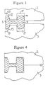
- Figure 1 is a cross-sectional view of a joint according to the second aspect of the invention provided with a seal ring according to the first aspect of the invention;
- Figures 2 and 2A are a cross-sectional view of a part of the seal ring of Figure 1;
- Figures 3 and 4 are sectional assembly views of part of the joint and seal ring shown in Figures 1 and 2;
- Figure 5 is a sectional view of part of a modified joint and seal ring according to the invention;
- Figures 6 and 7 are sectional assembly views of a part of a further modification of joint and seal ring according to the invention;
- Figures 8 and 9 are sectional assembly views of parts of further modifications of joint and seal ring according to the invention; and
- Figure 10 is a cross-sectional view of a further modification of joint and seal ring according to the invention.
- Referring to the drawings, and initially to Figure 1, a joint generally designated 1 comprises first and second flanged connecting
members flanged members - The annular seal ring comprises a
primary sealing portion 5 having angled sealing lips 6, 7, a radially outwardly extendingweb portion 8, and aspigot portion 9 extending transversely to the web portion and connected to the radially distal end thereof. As shown in Figure 1, theprimary sealing portion 5 andspigot portion 9 are received in respective complementary shaped recesses orgrooves - The
web portion 8 has opposed substantiallyparallel surfaces 8a, 8b with thespigot portion 9 havingopposed surfaces 9a, 9b extending substantially perpendicularly thereto. - It is important that the thickness of the
spigot portion 9 in the radial direction (dimension w in Figure 2A) is substantially greater than the thickness of theweb portion 8 in the transverse direction (dimension t in Figure 2A). This ensures that, when theseal ring 4 is in position in a joint, there is substantially no deflection of thespigot portion 9 in the radial direction relative to the web portion on tightening of the joint; radial deflection of the seal ring is therefore generally limited to radial stretch of the web portion and deflection of the seal lips of the sealingportion 5 thereby producing a more effective seal.
This feature also provides a stiff and rigid outer periphery for the seal ring, which is particularly important where large seal rings (e.g. diameter dimensions of 0.3 metres or above) are required. - Furthermore, the provision of a thickened
spigot portion 9 as described, ensures that shear stresses (which may result from connectingmembers web 8 or sealingportion 5 which would otherwise result in an inefficient seal being produced and/or damage. Typically a thickness ratio (w:t - see Figure 2A) of at least 1.25:1 and preferably greater than 1.5:1 produces enhanced seal ring characteristics.
It is furthermore important that the sealing lips 6, 7 project transversely from the web by a distance (dimension h in Figure 2A) which is substantially greater than the thickness of theweb 8 in the transverse direction (i.e. dimension t in Figure 2A). This ensures that the seal lips 6 may deflect radially to the required extent to produce an efficient seal on tightening of the joint such that the respective sealing point of the seal ring is displaced in the transverse direction from the web at an optimum distance. - It should also be noted that the
spigot portion 9 extends transversely to theweb portion 8 to an extent as great as theprimary sealing portion 5. If theseal ring 4 is dropped or knocked during transit or assembly, the impact shock and any resulting damage is therefore taken by thespigot portion 9, reducing the risk of damage to the sealing lips 6, 7. - Referring to Figures 3 and 4, on assembly of the joint 1, each of the portions of the spigot portion projecting transversely to the
web portion 8 engages with its respectiveannular recess 11 in theflanged members respective sealing surfaces members members members spigot portion 9 and hence not damage the sealing lips 6, 7 on theprimary sealing portion 5. - Furthermore, as described above, once the joint is assembled, shear stresses exerted on the seal ring due to misalignment of the flanged
members spigot portion 9 and not theprimary sealing portion 5. The construction therefore ensures that theprimary sealing portion 5 takes up only the contact sealing stresses caused by tightening the flange connecting bolts (not shown). As described above, a further advantage of thespigot portion 9 is that for large diameter seal rings (i.e. typically having a radius of 0.3 metres or more), the rigidity of the seal ring is effectively increased in the joint reducing the likelihood of unwanted flexion of the ring and enabling the general dimensions of the seal ring (particularly the web portion) to be kept to a minimum. - Prior to full tightening of the connecting bolts, the spigot portion will be guilded in its respective
annular recesses spigot portion 9. Under the action of flange bolting, the flangedmembers members - As the seal lips 6, 7 are forced into the recessed seat formed by the sealing
surfaces spigot portion 9 is deflected radially inwards. The radial deflection of the spigot portion can be controlled (e.g. limited) by controlling (e.g. reducing) the clearance between radially innermost portion of thespigot portion 9 and the radially innermost wall of theannular receiving recess 11 such that at a predetermined inward radial deflection of the ring the radially innermost portion of the spigot engages with the radially innermost wall ofannular recess 11 thereby preventing further radial deflection of the seal ring as a whole. This forces additional radial deflection (bending) of the seal lips 6, 7 as the joint is tightened, which promotes higher contact forces and therefore higher contact stresses between the lips 6, 7 andrespective sealing surface surface 12 and lip 7 and sealingsurface 13. - Referring to Figure 5, a modification of the
seal ring 5 andflanged connection members flanged member 3 is provided with a pressure tapping 16 extending from the exterior of the joint (not shown) to the interior annular space around theweb portion 8; there is further apressure balancing hole 21 throughweb portion 8. Further seallips spigot portion 9 which, when the seal is energised, provide a seal on the radially innermost faces ofannular recesses spigot portion 9 andprimary sealing portion 5 is effectively sealed. - Leakage of fluid pressure applied to the pressure tapping 16 will give an indication of an inefficient seal having been set up in the joint, and thus provides an effective means of testing the efficiency of the sealed joint prior to pressurising the conduit with fluid.
- Referring to Figure 6 and 7, a modified seal is shown having seal lips 6, 7 provided with a further sealing means in the form of crushable
metallic rims flanged connection conduits - Referring to Figure 8, in which like parts are denoted by like numerals, the seal ring has a
circumferential groove 21 running around the outermost face ofspigot portion 9; such a groove can provide the facility for the seal ring to be prised out after use and provide a means of suspending the ring (via thin twine or similar) in the vertical plane between two flanges of a horizontal pipe run. - In a further variation shown in Figure 9, the spigot has an outwardly tapering
face 22, tapering outwardly from the web portion 8 (rather than substantially perpendicular thereto), and there is a corresponding taper on the facingsurface 23 of the annular receiving recesses 10, 11. - Referring to Figure 10, there is shown a modified
seal ring 4 being interposed between a pair of misalignedflanged connecting members flange bolts 25draws connecting members surfaces spigot portion 9 and also the sealingportion 5. In applications where misaligned flanges are to be connected, it is preferred that the sealingportion 5 is thicker in the radial direction than would otherwise be necessary. It should also be noted that, unlike in relation to the other embodiments described, in the embodiment shown in Figure 10, theflanged connection members bolts 25 to be taken up in the sealingportion 5.
Claims (10)
- An annular seal ring comprising an integrally formed sealing portion (5), spigot portion (9) and interconnecting web portion (8), said sealing portion comprising a pair of annular seal lips (6,7) facing the spigot portion and extending in a transverse direction to said web portion, which web portion extends radially outwardly from said pair of seal lips to said spigot portion, which spigot portion is provided with spigot projections projecting in mutually opposed directions transversely to the web portion, wherein the thickness (w) of said spigot portion in the radial direction is substantially greater than the thickness (t) of the web portion in the transverse direction, and each respective seal lip is arranged to project transversely from said web portion by a distance (h) which is substantially greater than the thickness of said web portion in said transverse direction.
- A seal ring according to claim 1, wherein said pair of annular seal lips slope radially outwardly and toward one another to said web portion and/or are provided on respective radially outer portions of the sealing portion.
- A seal ring according to claim 1 or claim 2, wherein the thickness of the spigot portion in the radial direction is substantially greater than the thickness of the web in the transverse direction over substantially the whole transverse extent of the spigot portion and/or wherein the spigot portion projects transversely from the web portion at least as far as the sealing lips project transversely from the web portion.
- A seal ring according to any preceding claim, wherein each spigot projection is provided with a respective first transverse face portion facing a respective seal lip, said respective first face portion being preferably disposed substantially perpendicular to the radial direction.
- A seal ring according to claim 4, wherein each spigot projection is provided with a respective second transverse face portion spaced from the respective first transverse face position and facing in an opposed direction thereto, the first and second transverse face portions provided on each spigot projection being typically substantially parallel to one another.
- A seal ring according to claim 5, wherein the second transverse faces comprise the radially outermost extent of the seal ring.
- A seal ring according to any preceding claim, wherein the respective spigot projections are provided in the region of their transversely projecting limits with respective tapered or chamfered portions, and/or wherein the web portion is provided with substantially parallel opposed radially extending surfaces.
- A conduit joint comprising a seal ring according to any of claims 1 to 7, interposed at an interface between a pair of conduit or vessel defining members, said members being provided at said interface with respective recessed portions complementarily shaped and dimensioned to receive respective portions of the spigot portion, and the sealing portion of the seal ring, respectively, wherein a first one of said recessed portions comprises an annular groove having substantially parallel radially spaced sidewalls, and a second one of said recessed portions comprises an annular surface sloping away from said interface in an inwardly radial direction.
- A conduit joint according to claim 8, wherein the annular groove comprises first recess portion is provided with substantially parallel radially spaced sidewalls which are configured substantially perpendicularly to the radial direction and/or wherein the radially outermost sidewall of the annular groove is substantially more extensive in a direction perpendicular to the radial direction than the extent of the radially innermost sidewall of the annular groove in a direction perpendicular to the radial direction.
- A conduit joint according to claim 8 or 9, wherein the conduit-defining or vessel-defining members are flanged members arranged to be bolted together with the seal ring interposed therebetween to form a sealed joint.
Applications Claiming Priority (5)
| Application Number | Priority Date | Filing Date | Title |
|---|---|---|---|
| GB929205404A GB9205404D0 (en) | 1992-03-12 | 1992-03-12 | Seal ring and joint |
| GB9205404 | 1992-03-12 | ||
| GB9224993A GB2265196B (en) | 1992-03-12 | 1992-11-30 | Seal ring and joint |
| GB9224993 | 1992-11-30 | ||
| PCT/GB1993/000493 WO1993018331A1 (en) | 1992-03-12 | 1993-03-09 | Seal ring and joint |
Publications (2)
| Publication Number | Publication Date |
|---|---|
| EP0630457A1 EP0630457A1 (en) | 1994-12-28 |
| EP0630457B1 true EP0630457B1 (en) | 1997-08-06 |
Family
ID=26300512
Family Applications (1)
| Application Number | Title | Priority Date | Filing Date |
|---|---|---|---|
| EP93905549A Expired - Lifetime EP0630457B1 (en) | 1992-03-12 | 1993-03-09 | Seal ring and joint |
Country Status (10)
| Country | Link |
|---|---|
| US (1) | US5466018A (en) |
| EP (1) | EP0630457B1 (en) |
| JP (1) | JPH07504481A (en) |
| AT (1) | ATE156576T1 (en) |
| CA (1) | CA2131803A1 (en) |
| DE (1) | DE69312917T2 (en) |
| IN (1) | IN177398B (en) |
| MY (1) | MY109126A (en) |
| NO (1) | NO943340L (en) |
| WO (1) | WO1993018331A1 (en) |
Cited By (2)
| Publication number | Priority date | Publication date | Assignee | Title |
|---|---|---|---|---|
| WO2009111560A3 (en) * | 2008-03-04 | 2009-12-10 | Daniel Measurement And Control, Inc. | System and method of a flange seal ring |
| RU2504467C1 (en) * | 2012-10-26 | 2014-01-20 | Общество С Ограниченной Ответственностью Научно-Техническая Фирма "Бакс" | Device to control perpendicularity of flange surface with respect to tube axial line |
Families Citing this family (69)
| Publication number | Priority date | Publication date | Assignee | Title |
|---|---|---|---|---|
| US5628517A (en) * | 1993-06-01 | 1997-05-13 | Florida Atlantic University | Contracting/expanding self-sealing cryogenic tube seals |
| NO308329B1 (en) * | 1999-01-28 | 2000-08-28 | Den Norske Metallpakningsfabri | sealing |
| GB2363829B (en) * | 2000-06-22 | 2002-05-15 | Allan Cassells Sharp | A double-barrier metal-to-metal seal for use in hub-to-hub type pressure-containing connections |
| US6394505B1 (en) * | 2000-07-24 | 2002-05-28 | Geberit Technik | Connection between the intake end of a discharge pipe and the outlet end of a connection curve of a water toilet |
| US7107662B1 (en) * | 2000-12-21 | 2006-09-19 | Gene W. Arant, as Trustee | Method and a coupler for joining two steel pipes |
| US6450507B2 (en) | 2001-02-01 | 2002-09-17 | Abb Vetco Gray Inc. | Water ingress seal for tapered seals |
| FR2833680B1 (en) * | 2001-12-19 | 2005-12-23 | Air Liquide Electronics Sys | ANNULAR JOINT SEAL FOR TUBE ELEMENT |
| US20060254041A1 (en) * | 2001-12-21 | 2006-11-16 | Levario Alfredo G | Flared liner method of securing thermoplastically lined metal pipe |
| US20040094898A1 (en) * | 2002-11-20 | 2004-05-20 | Zheng Qiu Shi | Apparatus and method for inhibiting a flow of fluid through an interface between two joint members |
| JP4560669B2 (en) * | 2002-11-28 | 2010-10-13 | 株式会社フジキン | Fluid coupling and design method thereof |
| JP2004286195A (en) * | 2003-03-25 | 2004-10-14 | Nichias Corp | Ring type metal gasket |
| US20040189006A1 (en) * | 2003-03-28 | 2004-09-30 | Jurena Johnny E. | Torsional resistant metal gasket |
| JP4221348B2 (en) * | 2004-09-17 | 2009-02-12 | 日本ピラー工業株式会社 | Connection structure between flange piping and connection structure between flange piping and fluid equipment |
| JP4048193B2 (en) * | 2004-09-22 | 2008-02-13 | 日本ピラー工業株式会社 | Connection structure between integrated panel and fluidic device |
| JP4465254B2 (en) * | 2004-11-05 | 2010-05-19 | 日本ピラー工業株式会社 | Connection structure between integrated panel and fluidic device |
| JP4210643B2 (en) * | 2004-11-30 | 2009-01-21 | 日本ピラー工業株式会社 | Gasket for fluid |
| KR100914854B1 (en) * | 2004-11-30 | 2009-09-02 | 씨케이디 가부시키 가이샤 | Connection seal structure for fluidic device |
| JP4644477B2 (en) * | 2004-11-30 | 2011-03-02 | 日本ピラー工業株式会社 | Gasket for fluid |
| CN101069035B (en) * | 2004-11-30 | 2012-05-23 | 喜开理株式会社 | Connection sealing structure for fluid device |
| JP2006161873A (en) * | 2004-12-03 | 2006-06-22 | Nippon Pillar Packing Co Ltd | Connection structure of integrated panel with fluid device |
| JP4210668B2 (en) * | 2005-05-02 | 2009-01-21 | 日本ピラー工業株式会社 | Connection structure between integrated panel and fluidic device |
| JP4210669B2 (en) * | 2005-05-02 | 2009-01-21 | 日本ピラー工業株式会社 | Connection structure between integrated panel and fluidic device |
| TW200702582A (en) * | 2005-05-02 | 2007-01-16 | Nippon Pillar Packing | Structure for connection between integrated panel and fluid device |
| JP4210670B2 (en) * | 2005-05-02 | 2009-01-21 | 日本ピラー工業株式会社 | Gasket for fluid |
| KR20080026644A (en) * | 2005-07-12 | 2008-03-25 | 니혼삐라아코오교오카부시키가이샤 | Connection structure between integrated panel and fluid device |
| JP4257319B2 (en) * | 2005-07-12 | 2009-04-22 | 日本ピラー工業株式会社 | Connection structure between integrated panel and fluidic device |
| JP4257320B2 (en) * | 2005-07-13 | 2009-04-22 | 日本ピラー工業株式会社 | Connection structure between integrated panel and fluidic device |
| JP4512528B2 (en) * | 2005-07-13 | 2010-07-28 | 日本ピラー工業株式会社 | Connection structure between integrated panel and fluidic device |
| JP4512526B2 (en) * | 2005-07-12 | 2010-07-28 | 日本ピラー工業株式会社 | Connection structure between integrated panel and fluidic device |
| JP4378329B2 (en) * | 2005-08-11 | 2009-12-02 | 日本ピラー工業株式会社 | Connection structure between integrated panel and fluidic device |
| WO2007117209A1 (en) * | 2006-04-07 | 2007-10-18 | Sandvik Intellectual Property Ab | A connector assembly for an off shore riser |
| JP4465335B2 (en) * | 2006-08-09 | 2010-05-19 | 日本ピラー工業株式会社 | Connection structure between integrated panel and fluidic device |
| JP4411304B2 (en) * | 2006-08-09 | 2010-02-10 | 日本ピラー工業株式会社 | Connection structure between integrated panel and fluidic device |
| JP4445987B2 (en) * | 2007-09-06 | 2010-04-07 | 日本ピラー工業株式会社 | Connection structure between fluid equipment and fittings |
| US8033579B2 (en) * | 2007-10-05 | 2011-10-11 | Ckd Corporation | Fluid device connecting structure |
| US20090232595A1 (en) * | 2008-03-13 | 2009-09-17 | Benjamin Willemstyn | Connector, Gasket and Method of Attaching The Same |
| US8096560B2 (en) * | 2008-06-30 | 2012-01-17 | Vetco Gray Inc. | Metal-to-metal seal for smooth bore |
| US8226089B2 (en) * | 2008-06-30 | 2012-07-24 | Vetco Gray Inc. | Metal-to-metal seal for smooth bore |
| CA2650168C (en) * | 2009-01-19 | 2011-02-22 | Schlumberger Canada Limited | Barrier seal and assembly incorporating same |
| GB2475065B (en) * | 2009-11-04 | 2012-04-04 | Vector Int Ltd | Seal ring and joint |
| WO2011121380A1 (en) * | 2010-03-29 | 2011-10-06 | Fci Automotive Holding | Interfacial seal with a groove |
| EP2441997B1 (en) * | 2010-10-18 | 2012-11-28 | Sandvik Intellectual Property AB | A pipe coupling |
| US9045961B2 (en) * | 2011-01-31 | 2015-06-02 | National Oilwell Varco, L.P. | Blowout preventer seal and method of using same |
| JP5865692B2 (en) * | 2011-12-13 | 2016-02-17 | 武蔵エンジニアリング株式会社 | Seal structure of flow path connection |
| US9175541B2 (en) | 2012-04-10 | 2015-11-03 | National Oilwell Varco, L.P. | Blowout preventer seal assembly and method of using same |
| US9109732B2 (en) * | 2012-04-18 | 2015-08-18 | Vistadeltek, Llc | EZ-seal gasket for joining fluid pathways |
| BR102013021702A2 (en) * | 2013-08-26 | 2016-08-02 | Símeros Projetos Eletromecânicos Ltda | sealing assembly for flexible duct connector |
| ITUB20150570A1 (en) * | 2015-03-16 | 2016-09-16 | Istituto Naz Di Fisica Nucleare Ifnf | Process for the realization of a metal vacuum and radio frequency gasket and structure that incorporates it |
| GB2538323B (en) * | 2015-05-15 | 2017-11-01 | Evenort Ltd | Mechanical seal assembly |
| EP3356147A4 (en) * | 2015-09-30 | 2019-06-12 | Hewlett-Packard Development Company, L.P. | Fluid seals |
| EP3187763A1 (en) * | 2015-12-30 | 2017-07-05 | Alfa Laval Corporate AB | Coupling for connecting and sealing fluid handling components |
| SG10202012083YA (en) * | 2016-04-04 | 2021-01-28 | Ichor Systems Inc | Liquid delivery system |
| US10100958B2 (en) * | 2016-08-11 | 2018-10-16 | Trendsetter Engineering, Inc. | Gasket for use in sealing flanges together |
| DE202016104466U1 (en) * | 2016-08-12 | 2016-09-19 | Samson Ag | sealing arrangement |
| CN106641515A (en) * | 2016-11-21 | 2017-05-10 | 无锡金顶石油管材配件制造有限公司 | Petroleum pipeline coupling capable of preventing oil leakage |
| JP6416179B2 (en) * | 2016-12-13 | 2018-10-31 | Ckd株式会社 | Connection part seal structure and seal member |
| JP6905948B2 (en) * | 2018-03-13 | 2021-07-21 | 日本ピラー工業株式会社 | Gasket mounting structure on the block and gasket |
| JP6847888B2 (en) * | 2018-03-28 | 2021-03-24 | 日本ピラー工業株式会社 | Gasket mounting structure |
| JP6847074B2 (en) * | 2018-03-30 | 2021-03-24 | 日本ピラー工業株式会社 | Gasket and flow path joint structure |
| US20210054932A1 (en) * | 2018-03-30 | 2021-02-25 | Nippon Pillar Packing Co., Ltd. | Gasket and flow passage connector structure |
| JP6847075B2 (en) * | 2018-03-30 | 2021-03-24 | 日本ピラー工業株式会社 | Gasket and flow path joint structure |
| US11635142B2 (en) | 2019-11-14 | 2023-04-25 | Freudenberg Oil & Gas, Llc | Dual barrier seal |
| EP4077998A4 (en) | 2019-12-20 | 2024-03-13 | LTS Energy, Inc. | Under-balanced seal ring |
| NO20200110A1 (en) | 2020-01-28 | 2021-04-26 | Tp Products As | Seal ring |
| JP7398351B2 (en) * | 2020-09-15 | 2023-12-14 | 日本ピラー工業株式会社 | Gasket and flow joint structure |
| RU2748266C1 (en) * | 2020-11-16 | 2021-05-21 | Публичное акционерное общество «Татнефть» имени В.Д. Шашина | Flange connection seal |
| KR20240110853A (en) | 2021-11-24 | 2024-07-16 | 아이커 시스템즈, 인크. | fluid delivery system |
| EP4299961A1 (en) * | 2022-07-01 | 2024-01-03 | Gericke AG | Device for receiving and / or guiding bulk material and / or powders with a flange connection device |
| GB2643139A (en) * | 2024-07-31 | 2026-02-11 | Airbus Operations Ltd | Vacuum-insulated pipe assembly |
Family Cites Families (8)
| Publication number | Priority date | Publication date | Assignee | Title |
|---|---|---|---|---|
| US1821866A (en) * | 1929-11-01 | 1931-09-01 | Wylie G Wilson | Fluid tight joint and method of making |
| DE801604C (en) * | 1948-10-02 | 1951-01-15 | Basf Ag | Self-sealing cone |
| GB833252A (en) * | 1956-10-19 | 1960-04-21 | Ingenieurtiefbau Brandenburg V | Improvements in or relating to sealing arrangements for pipe joints |
| US3141685A (en) * | 1960-10-11 | 1964-07-21 | Gray Tool Co | Coupling with leak detecting means and sealing ring therefor |
| US3325176A (en) * | 1963-10-14 | 1967-06-13 | Gray Tool Co | Seal rings |
| FR1400302A (en) * | 1964-07-08 | 1965-05-21 | Thomson Houston Comp Francaise | Improvements to watertight seals |
| FR1583060A (en) * | 1968-05-14 | 1969-10-17 | ||
| FR2562630B1 (en) * | 1984-04-05 | 1988-11-25 | Commissariat Energie Atomique | FLEXIBLE METAL JOINT |
-
1993
- 1993-03-09 CA CA002131803A patent/CA2131803A1/en not_active Abandoned
- 1993-03-09 JP JP5515479A patent/JPH07504481A/en active Pending
- 1993-03-09 WO PCT/GB1993/000493 patent/WO1993018331A1/en not_active Ceased
- 1993-03-09 EP EP93905549A patent/EP0630457B1/en not_active Expired - Lifetime
- 1993-03-09 AT AT93905549T patent/ATE156576T1/en active
- 1993-03-09 DE DE69312917T patent/DE69312917T2/en not_active Expired - Fee Related
- 1993-03-09 US US08/302,659 patent/US5466018A/en not_active Expired - Fee Related
- 1993-03-11 IN IN147CA1993 patent/IN177398B/en unknown
- 1993-03-12 MY MYPI93000445A patent/MY109126A/en unknown
-
1994
- 1994-09-09 NO NO943340A patent/NO943340L/en unknown
Cited By (3)
| Publication number | Priority date | Publication date | Assignee | Title |
|---|---|---|---|---|
| WO2009111560A3 (en) * | 2008-03-04 | 2009-12-10 | Daniel Measurement And Control, Inc. | System and method of a flange seal ring |
| RU2443932C1 (en) * | 2008-03-04 | 2012-02-27 | Дэниел Мэжэмэнт энд Кэнтроул, Инк. | Method and device of circumferential sealing of flanges (versions) |
| RU2504467C1 (en) * | 2012-10-26 | 2014-01-20 | Общество С Ограниченной Ответственностью Научно-Техническая Фирма "Бакс" | Device to control perpendicularity of flange surface with respect to tube axial line |
Also Published As
| Publication number | Publication date |
|---|---|
| WO1993018331A1 (en) | 1993-09-16 |
| EP0630457A1 (en) | 1994-12-28 |
| JPH07504481A (en) | 1995-05-18 |
| NO943340D0 (en) | 1994-09-09 |
| ATE156576T1 (en) | 1997-08-15 |
| DE69312917T2 (en) | 1998-03-19 |
| MY109126A (en) | 1996-12-31 |
| CA2131803A1 (en) | 1993-09-16 |
| NO943340L (en) | 1994-09-09 |
| IN177398B (en) | 1997-01-11 |
| US5466018A (en) | 1995-11-14 |
| DE69312917D1 (en) | 1997-09-11 |
Similar Documents
| Publication | Publication Date | Title |
|---|---|---|
| US5466018A (en) | Seal ring and joint | |
| US11493158B2 (en) | Seal element for a pipe joint | |
| US4732416A (en) | Pipe connectors | |
| US4525001A (en) | Pipe connector with interengagable tubular pin and tubular box members | |
| AU655174B2 (en) | Pipe fitting with improved coupling body | |
| US4214763A (en) | Bore seal | |
| US10415729B2 (en) | Seal ring and joint | |
| US3756629A (en) | Stud system of joining pipe and couplings for same | |
| US4643457A (en) | Joint for plastic lined metal piping with reduced diameter pipe lap | |
| EP1481184B1 (en) | Pipe coupler | |
| EP0764251B1 (en) | Friction sealed coupling for pipe | |
| US4360227A (en) | Pipe coupling with improved gasket | |
| MXPA02003910A (en) | Apparatus for connecting tubular bodies. | |
| US7472911B2 (en) | Gasket for pipe coupling and pipe coupling incorporating same | |
| US4537425A (en) | High integrity flange connection arrangement | |
| US20010045709A1 (en) | Seal ring and joint | |
| US2769648A (en) | Reinforced t shaped seal for flanged pipe coupling | |
| US5573282A (en) | Low turbulence joint for lined slurry pipeline | |
| JPS6014692A (en) | High-pressure flow path connecting section | |
| KR20160061336A (en) | Metallic flange connection gasket | |
| US4861077A (en) | Trapezoidal seal ring connection | |
| US20020163193A1 (en) | Pipe coupling | |
| US4494776A (en) | Joint for plastic lined light-weight metal piping | |
| GB2265196A (en) | Seal ring and joint | |
| US4909548A (en) | Compound-taper flange assembly |
Legal Events
| Date | Code | Title | Description |
|---|---|---|---|
| PUAI | Public reference made under article 153(3) epc to a published international application that has entered the european phase |
Free format text: ORIGINAL CODE: 0009012 |
|
| 17P | Request for examination filed |
Effective date: 19940922 |
|
| AK | Designated contracting states |
Kind code of ref document: A1 Designated state(s): AT BE DE DK ES FR GB IT NL SE |
|
| RBV | Designated contracting states (corrected) |
Designated state(s): AT BE DE DK ES FR GB IT NL SE |
|
| GRAG | Despatch of communication of intention to grant |
Free format text: ORIGINAL CODE: EPIDOS AGRA |
|
| 17Q | First examination report despatched |
Effective date: 19960805 |
|
| GRAH | Despatch of communication of intention to grant a patent |
Free format text: ORIGINAL CODE: EPIDOS IGRA |
|
| GRAH | Despatch of communication of intention to grant a patent |
Free format text: ORIGINAL CODE: EPIDOS IGRA |
|
| RAP1 | Party data changed (applicant data changed or rights of an application transferred) |
Owner name: VECTOR INTERNATIONAL LIMITED |
|
| GRAA | (expected) grant |
Free format text: ORIGINAL CODE: 0009210 |
|
| AK | Designated contracting states |
Kind code of ref document: B1 Designated state(s): AT BE DE DK ES FR GB IT NL SE |
|
| PG25 | Lapsed in a contracting state [announced via postgrant information from national office to epo] |
Ref country code: NL Free format text: LAPSE BECAUSE OF FAILURE TO SUBMIT A TRANSLATION OF THE DESCRIPTION OR TO PAY THE FEE WITHIN THE PRESCRIBED TIME-LIMIT Effective date: 19970806 Ref country code: IT Free format text: LAPSE BECAUSE OF FAILURE TO SUBMIT A TRANSLATION OF THE DESCRIPTION OR TO PAY THE FEE WITHIN THE PRESCRIBED TIME-LIMIT;WARNING: LAPSES OF ITALIAN PATENTS WITH EFFECTIVE DATE BEFORE 2007 MAY HAVE OCCURRED AT ANY TIME BEFORE 2007. THE CORRECT EFFECTIVE DATE MAY BE DIFFERENT FROM THE ONE RECORDED. Effective date: 19970806 Ref country code: ES Free format text: THE PATENT HAS BEEN ANNULLED BY A DECISION OF A NATIONAL AUTHORITY Effective date: 19970806 Ref country code: DK Free format text: LAPSE BECAUSE OF NON-PAYMENT OF DUE FEES Effective date: 19970806 Ref country code: BE Effective date: 19970806 Ref country code: AT Effective date: 19970806 |
|
| REF | Corresponds to: |
Ref document number: 156576 Country of ref document: AT Date of ref document: 19970815 Kind code of ref document: T |
|
| REF | Corresponds to: |
Ref document number: 69312917 Country of ref document: DE Date of ref document: 19970911 |
|
| PG25 | Lapsed in a contracting state [announced via postgrant information from national office to epo] |
Ref country code: SE Effective date: 19971106 |
|
| ET | Fr: translation filed | ||
| NLV1 | Nl: lapsed or annulled due to failure to fulfill the requirements of art. 29p and 29m of the patents act | ||
| PLBE | No opposition filed within time limit |
Free format text: ORIGINAL CODE: 0009261 |
|
| STAA | Information on the status of an ep patent application or granted ep patent |
Free format text: STATUS: NO OPPOSITION FILED WITHIN TIME LIMIT |
|
| 26N | No opposition filed | ||
| PGFP | Annual fee paid to national office [announced via postgrant information from national office to epo] |
Ref country code: GB Payment date: 19990305 Year of fee payment: 7 |
|
| PGFP | Annual fee paid to national office [announced via postgrant information from national office to epo] |
Ref country code: FR Payment date: 19990331 Year of fee payment: 7 |
|
| PGFP | Annual fee paid to national office [announced via postgrant information from national office to epo] |
Ref country code: DE Payment date: 19990527 Year of fee payment: 7 |
|
| PG25 | Lapsed in a contracting state [announced via postgrant information from national office to epo] |
Ref country code: GB Free format text: LAPSE BECAUSE OF NON-PAYMENT OF DUE FEES Effective date: 20000309 |
|
| GBPC | Gb: european patent ceased through non-payment of renewal fee |
Effective date: 20000309 |
|
| PG25 | Lapsed in a contracting state [announced via postgrant information from national office to epo] |
Ref country code: FR Free format text: LAPSE BECAUSE OF NON-PAYMENT OF DUE FEES Effective date: 20001130 |
|
| REG | Reference to a national code |
Ref country code: FR Ref legal event code: ST |
|
| PG25 | Lapsed in a contracting state [announced via postgrant information from national office to epo] |
Ref country code: DE Free format text: LAPSE BECAUSE OF NON-PAYMENT OF DUE FEES Effective date: 20010103 |