EP0629501B1 - Anilox coater with brush - Google Patents
Anilox coater with brush Download PDFInfo
- Publication number
- EP0629501B1 EP0629501B1 EP93308811A EP93308811A EP0629501B1 EP 0629501 B1 EP0629501 B1 EP 0629501B1 EP 93308811 A EP93308811 A EP 93308811A EP 93308811 A EP93308811 A EP 93308811A EP 0629501 B1 EP0629501 B1 EP 0629501B1
- Authority
- EP
- European Patent Office
- Prior art keywords
- reservoir
- applicator roller
- air bubbles
- brush
- cells
- Prior art date
- Legal status (The legal status is an assumption and is not a legal conclusion. Google has not performed a legal analysis and makes no representation as to the accuracy of the status listed.)
- Expired - Lifetime
Links
Images

Classifications
-
- B—PERFORMING OPERATIONS; TRANSPORTING
- B41—PRINTING; LINING MACHINES; TYPEWRITERS; STAMPS
- B41F—PRINTING MACHINES OR PRESSES
- B41F31/00—Inking arrangements or devices
- B41F31/02—Ducts, containers, supply or metering devices
- B41F31/027—Ink rail devices for inking ink rollers
-
- B—PERFORMING OPERATIONS; TRANSPORTING
- B41—PRINTING; LINING MACHINES; TYPEWRITERS; STAMPS
- B41F—PRINTING MACHINES OR PRESSES
- B41F23/00—Devices for treating the surfaces of sheets, webs, or other articles in connection with printing
- B41F23/08—Print finishing devices, e.g. for glossing prints
-
- B—PERFORMING OPERATIONS; TRANSPORTING
- B41—PRINTING; LINING MACHINES; TYPEWRITERS; STAMPS
- B41F—PRINTING MACHINES OR PRESSES
- B41F31/00—Inking arrangements or devices
- B41F31/02—Ducts, containers, supply or metering devices
- B41F31/08—Ducts, containers, supply or metering devices with ink ejecting means, e.g. pumps, nozzles
-
- B—PERFORMING OPERATIONS; TRANSPORTING
- B41—PRINTING; LINING MACHINES; TYPEWRITERS; STAMPS
- B41P—INDEXING SCHEME RELATING TO PRINTING, LINING MACHINES, TYPEWRITERS, AND TO STAMPS
- B41P2200/00—Printing processes
- B41P2200/10—Relief printing
- B41P2200/12—Flexographic printing
Definitions
- This invention relates generally to sheet-fed or web-fed, rotary offset or flexographic printing press equipment, and in particular to an improved coating apparatus for supplying inks or protective and/or decorative coatings from a reservoir to a plate cylinder or to a blanket cylinder.
- Fluid metering or applicator rollers are used in the printing industry to transfer measured amounts of printing ink or a protective and/or decorative liquid coating to a plate cylinder or to a blanket cylinder.
- the surface of the applicator roller is engraved with an array of closely spaced, shallow depressions referred to as "cells”. Ink or liquid coating material flows into the cells as the anilox roller turns within a reservoir.
- the engraved transfer surface of the applicator roller is scraped with a doctor blade to remove excess ink or liquid coating material.
- the ink or liquid coating material remaining on the anilox roller is contained within the cells.
- the plate cylinder or blanket cylinder transfers ink or liquid coating material from the cells of the anilox roller over all or a portion of the surface of printed sheets or a web of material, either plastic or paper, onto which the desired image is imprinted.
- the anilox roller has a cylindrical surface and may be constructed in various diameters and lengths containing cells of various sizes and shapes.
- the volumetric capacity of an anilox roller is established during manufacturing and is dependent upon the selection of cell size, shape and number of cells per unit area.
- the cell pattern may be fine (many small cells per unit area) for lower coating weight jobs, for example UV coatings, or coarse (fewer large cells per unit area) for applying a protective coating or an adhesive coating to heavy stock.
- Applicator rollers are journaled for rotation about an axis parallel with the rotary axis of a plate cylinder or blanket cylinder.
- a doctor blade head is extendable and retractable into and out of operative engagement with the applicator roller. In the operative position, the periphery of the applicator roller extends into an elongated reservoir cavity within the doctor blade head.
- the doctor blade head may have one, two or more doctor blades which seal against the cylindrical anilox surface and enclose the reservoir. Some doctor blades seal against an ink roller to form the bottom of an ink reservoir, while other doctor blades are used for doctoring the thickness of the liquid film on the applicator roller, in a reverse angle orientation.
- a limitation on the performance of engraved applicator rollers is the entrapment of small air bubbles within the engraved cells.
- the entrapped air limits the amount of ink or other liquid media flowing into the cells.
- the entrapped air within the cell prevents the cell walls from becoming completely wetted with the ink or liquid coating material, and must be displaced before the cell can be filled.
- the amount of air entrapped within the anilox cells is proportional to press speed, the flow characteristics of the liquid media, and the speed of rotation of the applicator roller within the reservoir.
- the entrapped air causes starvation and uneven replenishment of liquid material; the ink or protective coating material is unable to fill the anilox cells in those areas where air bubbles have been entrapped.
- the quality of the print and/or protective coating is compromised by starvation of the anilox cells.
- One method for overcoming the starvation condition caused by entrapment of air bubbles pulled in by the exposed peripheral surface of the applicator roller is to reduce the press speed until uniform inking or coating is achieved.
- Another source of uneven filling of ink into the anilox cells is the presence of entrapped air bubbles in the ink or liquid material within the reservoir.
- Ambient air pulled in by the rotating anilox roller becomes mixed with the ink or liquid coating material.
- the entrapped air bubbles become dispersed as an air emulsion throughout the reservoir because of the turbulence produced by rotation of the peripheral surface of the anilox roller within the doctor reservoir cavity.
- the entrapped air bubbles are typically larger than the cell diameter, and oppose wetting contact of the ink or liquid coating material with the cell sidewall surfaces. Good wetting contact is essential so that the cells will be filled by capillary flow.
- baffle arrangements have been proposed for separating the entrapped air bubbles from the ink or liquid coating material. Such attempts involve venting a portion of the entrapped air from the reservoir prior to scraping with the doctor blade, as well as transversely partitioning the reservoir to reduce turbulent movement of the ink or liquid coating material.
- apparatus for applying liquid material from a supply to an applicator roller having cells on its peripheral surface comprises a doctor blade head having an elongated cavity formed therein defining a reservoir for receiving liquid material from a supply, the doctor blade head being adapted for alignment with an applicator roller in an operative position with a portion of the applicator roller being received within the reservoir cavity for wetting contact with liquid material contained therein and including at least one doctor blade extending along the reservoir cavity for engagement against the peripheral surface of the applicator roller in the operative position, and wiping means disposed within the reservoir cavity for wiping engagement against the peripheral surface of the applicator roller in the operative position, the wiping means being fluid permeable and operable to sweep entrapped air away from the cells to promote the flow of liquid material into the cells.
- a method for removing air bubbles entrapped within cells of an engraved applicator roller, in which an engraved surface portion of the applicator roller is extended into a reservoir in wetting contact with liquid coating material contained therein, a pair of spaced doctor blades are held in contact with the applicator roller, and the engraved surface portion of the applicator roller is wiped within the reservoir, and the engraved surface portion of the roller is wiped with a fluid-permeable brush, portions of the brush puncturing entrapped air bubbles and sweeping the air bubbles away from the cells and promoting the flow of liquid material into the cells.
- the brush has an elongated array of resilient bristles which are disposed for wiping engagement against the engraved surface of the applicator roller when the doctor blades are sealed against the applicator roller in the operative position.
- the brush is an elongated body of open cell foam. The brush may be mounted on the doctor blade head, or on a doctor blade.
- the bristles of the brush puncture the entrapped air bubbles and sweep the entrapped air away from the cells.
- the bristles of the brush are wetted with the liquid material in the reservoir, and liquid material carried on the tips of the bristles wets the cell entrances, which promotes filling by capillary flow.
- the bristle tips also break the airlocks in the individual cells. Because of the sweeping action of the bristles as the entrapped air bubbles are punctured and swept away, a relatively low pressure condition is established within the cells. The low pressure differential condition promotes the flow of liquid material into the cells.
- the bristles of the brush also break up entrapped air bubbles which are dispersed through the liquid material in the reservoir.
- the elongated brush which extends from one end of the doctor blade head to the other, serves as a baffle which blocks the transfer of dispersed air bubbles from the liquid material in the upper reservoir chamber above the brush to the lower reservoir chamber below the brush where the cells are being filled.
- Pump means may be coupled to the supply and to the reservoir cavity for inducing flow of liquid material from the supply into the reservoir cavity and for returning excess liquid material by suction flow from the reservoir cavity to the supply.
- this is achieved in a manner that maintains at least the upper chamber below atmospheric pressure.
- the pump means includes both pressure pumping means connected to the lower chamber and suction pumping means connected to the upper chamber.
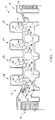
- the present invention is incorporated in a new and improved in-line doctor blade apparatus, herein generally designated 10, for use in applying a protective and/or decorative coating or inks to the freshly printed surface of sheets in a sheet-fed or web-fed, rotary offset or flexographic printing press, herein generally designated 12.
- the doctor blade coating apparatus 10 is illustrated as installed in a four color printing press 12, such as that manufactured by Heidelberger Druckmaschinen AG of the Federal Republic of Germany under its designation Heidelberg Speedmaster 102V (40 inches or 102 cm), and which includes a press frame 14 coupled at one end, herein the right end, with a sheet feeder 16 from which sheets, herein designated 18, are individually and sequentially fed into the press, and at the opposite end, with a sheet delivery stacker 20 in which the finally printed sheets are collected and stacked. Interposed between the sheet feeder 16 and the sheet delivery stacker 20 are four substantially identical sheet printing units 22, 24, 26 and 28 which can print different color inks onto the sheets as they are moved through the press 12.
- a four color printing press 12 such as that manufactured by Heidelberger Druckmaschinen AG of the Federal Republic of Germany under its designation Heidelberg Speedmaster 102V (40 inches or 102 cm)
- a press frame 14 coupled at one end, herein the right end, with a sheet feeder 16 from which sheets, herein designated 18, are individually and sequentially fed into the press, and at the
- each of the printing units 22, 24, 26 and 28 is substantially identical and of conventional design, herein including a sheet transfer cylinder 30, a plate cylinder 32, a blanket cylinder 34 and an impression cylinder 36, with each of the first three printing units 22, 24 and 26 having a transfer cylinder 38 disposed to withdraw the freshly printed sheets from the adjacent impression cylinder and transfer the freshly printed sheets to the next printing station via a transfer cylinder 40.
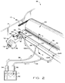
- the final printing station 28 herein is shown as equipped with a delivery cylinder 42 which functions to support the printed sheet 18 as it is moved from the final impression cylinder 36 by a delivery conveyor system, generally designated 44, to the sheet delivery stacker 20.
- the delivery conveyor system 44 as shown in Figure 2 is of conventional design and includes a pair of endless delivery gripper chains 46, only one of which is shown carrying laterally disposed gripper bars having gripper elements used to grip the leading edge of a sheet 18 after it leaves the nip between the delivery cylinder 42 and impression cylinder 36 of the last printing unit 28.
- the delivery chains 46 pull the sheet away from the impression cylinder 36 and convey the freshly printed sheet to the sheet delivery stacker 20 where the grippers release the finally printed sheet.
- the endless delivery chains 46 are driven in synchronous timed relation to the impression cylinder 36 by sprocket wheels fixed adjacent the lateral ends of a delivery drive shaft 48 which has a mechanically geared coupling (not shown) to the press drive system.
- the delivery drive shaft 48 extends laterally between the sides of the press frame 14 adjacent the impression cylinder 36 of the last printing unit 28, and is mounted in parallel with the axis of the impression cylinder 36.
- the delivery cylinder 42 which is constructed to allow adjustments in diameter by suitable means, is attached to the delivery drive shaft 48 so that the delivery cylinder 42 is also rotated in precise timed relation with the impression cylinder.
- vacuum transfer apparatus of the type disclosed in U.S. Patent 5,127,329 entitled “Vacuum Transfer Apparatus for Sheet-Fed Printing Presses", to Howard W. DeMoore has been used.
- the vacuum transfer apparatus disclosed in that application can be used in place of delivery cylinders or skeleton wheels to transfer the unprinted side of the sheet away from the delivery drive shaft 48 so that the wet ink surface of the sheets do not come into contact with any press apparatus.
- the inline doctor blade coating apparatus 10 for applying the protective or decorative coating to the sheets 18 enables the press 12 to be operated in the normal manner and at high speed without the loss of the final printing unit 28, and without requiring any substantial press modifications by employing the existing press delivery drive shaft 48 as the mounting location for the coating applicator 10.
- the coating apparatus 10 of the present invention includes a relatively simple, positive acting and economical doctor blade coating unit, generally designated 50, mounted to the press frame 14 downstream of the delivery drive shaft 48 and positioned to apply liquid coating material to the blanket surface of a delivery cylinder 42 mounted on the delivery drive shaft.
- the doctor blade coating unit 50 is supported on a pair of side frames 52, only one of which is shown, it being understood that the other side frame is substantially the same as that of the side frame illustrated, attached to each side of the press frame 14.
- each side frame 52 Pivotally mounted to one end of each side frame 52 is a support bracket 54 carrying one end of the doctor blade coating unit 50 and cooperating liquid material applicator roller 58 each disposed to extend laterally across the press 12 parallel with the delivery drive shaft 48.
- the coating unit 50 is mounted between the upper and lower runs of the delivery chains 46 downstream of the delivery drive shaft 48, and positioned so that the outer peripheral surface 60 of the applicator roller 58 is engageable against the coating blanket transfer surface of a delivery blanket cylinder 42 mounted on the delivery drive shaft 48.
- the support bracket 54 is pivotally attached to the end of the side frame 52 by a shaft 62 disposed at the lower end portion of the bracket.
- the assembly is pivoted about the shaft 62 by an extensible power cylinder 64, herein shown as a pneumatic cylinder, one end 66 of which is secured to the side frame 52, and the opposite end 68 of which is coupled through a pivot shaft 70 to the upper end portion of the bracket.
- an extensible power cylinder 64 herein shown as a pneumatic cylinder
- the engagement pressure of the coating applicator roller 58 against the surface of the coating blanket cylinder 42 may be controlled, and the applicator roller may be completely disengaged from the coating blanket cylinder.
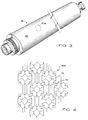
- the coating applicator roller 58 which is of conventional design and preferably one such as the anilox engraved roller manufactured by A.R.C. International of Charlotte, North Carolina and sold under the name "PRINTMASTER" having an engraved ceramic or chrome outer peripheral surface 60, is designed to pick up a predetermined uniform thickness of liquid coating material or ink from the reservoir of the doctor blade head 50, and then uniformly transfer the ink or coating material to the transfer surface of the blanket cylinder 42.
- the applicator roller 58 may also be used as an ink metering or transfer roller, which is used extensively in the flexographic printing trade to transfer closely controlled quantities of ink from fountain rollers running in an ink bath to a printing plate cylinder.
- the transfer surface 60 of the applicator roller 58 is engraved to produce tiny depressions or cells 72 which extend uniformly over the surface of the applicator roller, with the aggregate volume of the cells defining a reservoir from which a liquid coating material is transferred onto the coating blanket cylinder.
- the cell configuration illustrated in Figure 4 is hexagonal, with adjacent cells 72 being interconnected by channels 74.
- a suitable motor 76 herein a hydraulic motor, is attached to one of the side frames 52 and coupled to a suitable hydraulic fluid source (not shown) through fittings 78, 80.
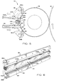
- the pickup roller 58 has a peripheral surface portion 58P which projects radially into a doctor reservoir 82 containing the supply of liquid coating material or ink.
- the reservoir cavity 82 is formed within the elongated doctor blade head 88 having a generally C-shaped cross-section with an opening 90 extending longitudinally along one side facing the pickup roller 58.
- the reservoir 82 is supplied with liquid material or ink from a supply drum 92 disposed in a remote location within or near the press 12.
- the doctor blade head 88 is removably attached to the brackets 54, herein by bolts having enlarged, knurled heads, and which can be threaded through slots formed in the brackets to clamp the doctor blade head in place on the brackets.
- the coating material or ink is circulated through the reservoir 82 by two pumps 94 and 96 as shown in Figure 2.
- Pump 94 draws the liquid material L from the supply drum 92 via a supply line 98 and discharges it into a bottom region of the reservoir 82 through a delivery port 100, and the other pump 96 acts to provide suction to a return line 102 by branch lines 102A, 102B, coupled adjacent a top region of the reservoir through return ports 104A, 104B for withdrawing excess liquid coating material or ink from the reservoir.
- the general arrangement of the applicator roller 58, doctor blades 84 and 86, and end seals in combination provide an enclosed reservoir 82.
- the doctor blade reservoir 82 is not pressurized as taught by the prior art. Instead, coating liquid or ink is supplied to the doctor blade reservoir 82 by suction flow produced by the pump 96, and assisted by the pump 94.
- the suction pump 96 applies a vacuum or suction force in the reservoir which draws liquid material L from the supply through the supply conduit 98 to the reservoir. Excess liquid material L from the doctor blade reservoir 82 is returned through the return conduit 102 into the remote reservoir 92 by the suction flow.
- the pump 94 assists the circulation of liquid coating material. A positive pressure condition within the doctor blade reservoir is avoided, and a below atmospheric vacuum pressure level is maintained.
- the liquid material is delivered into the lower region 82A of the doctor blade reservoir, and is withdrawn from an upper region 82B of the reservoir through the return conduits 102A, 102B.
- the liquid level elevation of the return ports is preferably selected to provide for the accumulation of liquid coating material or ink in slightly more than about half of the doctor blade chamber 82, thereby ensuring that the engraved surface 60 of the pickup roller 58 will be thoroughly wetted by the coating material or ink L as it turns through the doctor blade chamber 82.
- the reservoir 82 is bounded vertically by the lower and upper doctor head shoulders 88A, 88B.
- the return ports 104A, 104B and return lines 102A, 102B are located at a liquid level R intermediate the limits established by the lower and upper shoulders. Any excess liquid coating material or ink which rises above the liquid level R of the return ports will be suctioned away by the pump 96.
- the auxiliary supply pump 94 provides positive flow input to the doctor blade reservoir 82 at a fixed flow rate.
- the return suction pump 96 has a faster suction flow rate than the supply flow rate. Consequently, a positive pressure buildup in the doctor blade reservoir 82 cannot occur.
- the liquid level within the doctor blade chamber 82 can be closely controlled, without positive pressure buildup, thereby reducing leakage through the end seals.
- the doctor blade chamber 82 is maintained at a pressure level below atmospheric by the suction action of the return suction flow pump 96.
- the coating liquid L rises to the liquid level of the return port R and is drawn off immediately by the suction pump 96. Additionally, air within the upper doctor blade chamber 82B is also evacuated, thereby reducing the doctor blade chamber pressure to a level below atmospheric.
- the entrapped air bubbles in the applicator roller cells are displaced from the cells by wiping the surface 60 of the engraved applicator roller 58 with the bristles 106B of an elongated brush 106.
- the elongated brush 106 is mounted within a rectangular channel 108 which intersects the doctor blade head 88 along its length.
- the rectangular channel 108 is centered substantially between the elevation of the supply port 100 and the return ports 104A, 104B.
- the doctor blades 84, 86 are sealed against the engraved surface 60 of the applicator roller 58.
- the bristles 106B of the brush 106 are disposed in wiping engagement of the engraved surface 60.
- the bristles 106B puncture the entrapped air bubbles and sweep the entrapped air away from the cells 72.
- the bristles of the brush 106 are wetted with the liquid material in the reservoir, and the liquid material on the tips of the brush wet the cell entrances, thereby promoting capillary flow. Because of the sweeping action of the bristles 106B as the entrapped air bubbles are punctured and swept away, a relatively low pressure condition is established in the cells as they pass by the brush. The low pressure differential flow through condition promotes the flow of liquid material into the cells.
- the bristles act as a pre-shear means for reducing the dynamic viscosity of the liquid material.
- the bristles 106B of the brush also break up entrapped air bubbles which may be dispersed through the liquid material in the upper region 82B of the reservoir.
- the elongated brush 106 which extends from one end of the doctor blade head to the other, serves as a liquid permeable partition which blocks the transfer of dispersed air bubbles from the liquid material in the upper region 82B above the brush 106, and prevents transfer of the dispersed bubbles into the lower region 82A below the brush 106 in the region where the cells are being filled.
- Transfer of dispersed air bubbles from the upper region 82B into the lower region 82A is also inhibited by maintaining a below atmospheric pressure level in the upper region 82B. Because liquid coating material is being fed into the lower region 82A, a slightly positive pressure differential arises across the brush 106 which opposes the migration of air bubbles from the upper region into the lower region.
- the brush is an elongated, resilient block 110 of open-cell foam material.
- Suitable open-cell foam materials include polyurethane, plasticized polyvinylchloride and rubber, with the polyurethane foam being preferred.
- the open-cell foam block 110 is secured within the channel 108, and has an end portion disposed in wiping engagement with the engraved surface 60 of the applicator roller 58.
- the open-cell foam brush 110 is under compression in the operative position as shown in Figure 7 to ensure clean wiping action.
- the density of the open-cell foam brush is selected in the range of from about one pound to about two pounds per cubic foot (32 Kgs/cu m).
- the density of the open-cell foam brush 110 should be selected to provide a permeability which is compatible with the particular liquid coating material to permit excess liquid coating material to escape from the lower chamber 82A through the brush into the upper chamber 82B for return to the supply through the conduit 102A.
- FIG 9 Yet another embodiment is illustrated in Figure 9, in which the brush 106 is mounted on the upper doctor blade 84.
- the bristles of the brush 106 wipe against engraved surface 60 of the applicator roller 58.
- the bristles puncture the entrapped air bubbles and sweep the entrapped air away from the engraved cells.
- Liquid coating material on the tips of the bristles wet the cell entrances thereby promoting capillary flow, as previously discussed in connection with the embodiment illustrated in Figure 5.
- the coater assembly is first locked into the operative position on the press frame with the doctor blades 84, 86 engaging the applicator roller 58.
- the hydraulic motor 76 rotates the applicator roller 58 as coating liquid material is pumped under pressure from the reservoir 92 into the lower region 82B within the doctor blade assembly.
- the liquid coating material spreads over the engraved surface of the applicator roller 58 and is metered by the lower doctor blade 86 during counterclockwise rotation as shown in Figure 5.
- Liquid coating material is picked up by the engraved surface 60 of the applicator roller 58, and excess coating is returned to the supply reservoir 92 through the return conduit 102. According to this arrangement, sufficient flow of liquid coating material is maintained combined with the wiping action of the bristles to avoid clogging the flow conduits or the cells of the engraved roller with dried coating and to avoid starving the ends of the applicator roller.
- the coating apparatus 10 of the present invention provides a highly reliable, effective and economical in-line apparatus for applying coating material uniformly to the freshly printed sheets 18 in a sheet-fed, offset rotary printing press 12.
Landscapes
- Coating Apparatus (AREA)
- Inking, Control Or Cleaning Of Printing Machines (AREA)
Applications Claiming Priority (2)
| Application Number | Priority Date | Filing Date | Title |
|---|---|---|---|
| US78427 | 1993-06-17 | ||
| US08/078,427 US5425809A (en) | 1993-06-17 | 1993-06-17 | Anilox coater with brush |
Publications (2)
| Publication Number | Publication Date |
|---|---|
| EP0629501A1 EP0629501A1 (en) | 1994-12-21 |
| EP0629501B1 true EP0629501B1 (en) | 1999-09-15 |
Family
ID=22143958
Family Applications (1)
| Application Number | Title | Priority Date | Filing Date |
|---|---|---|---|
| EP93308811A Expired - Lifetime EP0629501B1 (en) | 1993-06-17 | 1993-11-04 | Anilox coater with brush |
Country Status (6)
| Country | Link |
|---|---|
| US (2) | US5425809A (ja) |
| EP (1) | EP0629501B1 (ja) |
| JP (1) | JPH07101041A (ja) |
| KR (1) | KR950000411A (ja) |
| CA (1) | CA2102157C (ja) |
| DE (1) | DE69326452T2 (ja) |
Families Citing this family (34)
| Publication number | Priority date | Publication date | Assignee | Title |
|---|---|---|---|---|
| US5683508A (en) † | 1995-08-25 | 1997-11-04 | Fit Group, Inc. | Coating apparatus and method for dispensing a liquid, and draining and cleaning a coating apparatus |
| US5651316A (en) | 1995-10-02 | 1997-07-29 | Howard W. DeMoore | Retractable printing/coating unit operable on the plate and blanket cylinders simultaneously from the dampener side of the first printing unit or any consecutive printing unit of any rotary offset printing press |
| US5598777A (en) | 1995-10-02 | 1997-02-04 | Howard W. DeMoore | Retractable printing/coating unit operable on the plate and blanket cylinders |
| JPH09136398A (ja) | 1995-10-02 | 1997-05-27 | Howard W Demoore | あらゆる輪転オフセット印刷機の第1の印刷ユニット又はそれに続くいずれかの印刷ユニットの湿し装置側から版胴及びブランケット胴上で同時に作動可能な引込み式印刷/コーティングユニット |
| US5983797A (en) * | 1997-11-17 | 1999-11-16 | Howard W. DeMoore | End seal engaging bearer of anilox roller assembly |
| EP0951998B1 (en) * | 1998-04-23 | 2003-07-09 | Umetani Mfg.Co.,Ltd. | Printing machine for corrugated board sheets and method of cleaning ink fountain of the machine |
| US6152068A (en) * | 1998-06-22 | 2000-11-28 | Hunter Douglas Inc. | Apparatus for manufacturing an adjustable covering for architectural openings |
| AU2143200A (en) | 1998-10-23 | 2000-05-15 | Royse Manufacturing Co. | Web coating material supply apparatus and method for a printing system |
| AU3236400A (en) | 1999-03-03 | 2000-09-21 | James F Price | Keyless inker for a printing press |
| US6672211B2 (en) * | 1999-03-03 | 2004-01-06 | James F. Price | Inking systems for printing presses |
| US6895861B2 (en) * | 2003-07-11 | 2005-05-24 | James F. Price | Keyless inking systems and methods using subtractive and clean-up rollers |
| DE29913778U1 (de) * | 1999-08-06 | 1999-09-30 | Roland Man Druckmasch | Beschichtungseinrichtung in einer Druckmaschine |
| US6576059B2 (en) * | 1999-11-22 | 2003-06-10 | Harris & Bruno Company, Inc. | Chambered doctor blade system for water-based and UV-based coatings |
| US6383296B1 (en) | 1999-11-22 | 2002-05-07 | Harris & Bruno Machine Co. | Chambered doctor blade with automatic cleanup and ink replacement |
| DE29922546U1 (de) | 1999-12-22 | 2000-02-17 | Roland Man Druckmasch | Dosiersystem für Beschichtungsflüssigkeiten in einer Beschichtungseinheit |
| US6729656B2 (en) * | 2002-02-13 | 2004-05-04 | T.S.D. Llc | Debit card having applied personal identification number (PIN) and scratch-off coating and method of forming same |
| US6852191B2 (en) * | 2002-08-01 | 2005-02-08 | Equipements De Transformation Imac | Method and apparatus for manufacturing pressure sensitive adhesive label stocks with printing under adhesive and product produced thereby |
| DE10236781B4 (de) * | 2002-08-14 | 2009-11-19 | Manroland Ag | Beschichtungseinrichtung für eine Druck- oder Beschichtungsmaschine |
| DE102004033338B4 (de) * | 2004-07-09 | 2010-12-09 | Airbus Deutschland Gmbh | Spritzvorrichtung mit Tröpfchenrückhalt und Verfahren |
| US7273007B2 (en) | 2004-09-27 | 2007-09-25 | Printing Research, Inc. | Portable printer coater |
| ES2264643B1 (es) * | 2005-06-22 | 2007-10-01 | Comexi, S.A. | Dipositivo y metodo de impresion usando tintas curables por energia para impresora flexografica. |
| DE102005030945A1 (de) * | 2005-06-30 | 2007-01-11 | Polytype Converting S.A. | NIP-Beschichtung |
| JP4508978B2 (ja) * | 2005-08-11 | 2010-07-21 | キヤノン株式会社 | 液体塗布装置およびインクジェット記録装置 |
| US8348991B2 (en) * | 2006-03-29 | 2013-01-08 | Boston Scientific Scimed, Inc. | Stent with overlap and high expansion |
| US8105066B2 (en) * | 2007-01-17 | 2012-01-31 | 3D Systems, Inc. | Cartridge for solid imaging apparatus and method |
| DE102009005371A1 (de) | 2009-01-21 | 2010-07-29 | OCé PRINTING SYSTEMS GMBH | Anordnung zum Austausch eines flüssigen Mediums zwischen einer das flüssige Medium aufweisenden Kammer und einer rotierenden Transporteinheit für das flüssige Medium bei einem elektrografischen Druckgerät |
| KR20100123973A (ko) * | 2009-05-18 | 2010-11-26 | 삼성전자주식회사 | 컬러 필터, 그 제조 장치 및 그 제조 방법 |
| DE102010008241B4 (de) * | 2010-02-17 | 2015-11-26 | Océ Printing Systems GmbH & Co. KG | Vorrichtung zur Entwicklung von auf einem Ladungsbildträger erzeugten Ladungsbildern bei einem elektrografischen Druck- oder Kopiergerät |
| JP5735300B2 (ja) * | 2011-02-17 | 2015-06-17 | 富士機械工業株式会社 | グラビア塗工装置 |
| WO2012148428A1 (en) * | 2011-04-29 | 2012-11-01 | Hewlett-Packard Development Company, L.P. | Apparatus, printers, and methods to remove material from a printer surface |
| WO2014159780A2 (en) | 2013-03-13 | 2014-10-02 | Probity Engineering, Llc | Ink fountain apparatus and method of adjusting ink flow for a flexographic printing apparatus |
| CN103522747B (zh) * | 2013-09-03 | 2015-09-30 | 汕头市华鹰软包装设备总厂有限公司 | 小车式油墨盘装置 |
| DE102015005535A1 (de) * | 2015-05-03 | 2016-11-03 | Harris & Bruno Europe GmbH | Reinigungsvorrichtung für eine Walze, Druck- oder Beschichtungswerk sowie Verfahren zum Reinigen einer Walze |
| US20210070032A1 (en) * | 2019-09-05 | 2021-03-11 | Harper Corporation Of America | Engraved roller for flexographic and gravure printing |
Citations (2)
| Publication number | Priority date | Publication date | Assignee | Title |
|---|---|---|---|---|
| US4538541A (en) * | 1982-03-29 | 1985-09-03 | Johannes Zimmer | Method of and apparatus for applying a uniform layer of liquid to a surface |
| US5176077A (en) * | 1991-08-30 | 1993-01-05 | Howard W. DeMoore | Coating apparatus for sheet-fed, offset rotary printing presses |
Family Cites Families (14)
| Publication number | Priority date | Publication date | Assignee | Title |
|---|---|---|---|---|
| US3014454A (en) * | 1959-05-22 | 1961-12-26 | Smejda Richard Kurt | Stripe applicators |
| US3883291A (en) * | 1973-11-19 | 1975-05-13 | Xerox Corp | Oil applicator for reproduction machine fuser |
| US4158333A (en) * | 1978-05-01 | 1979-06-19 | Anpa Research Institute | Inking baffle for rotary newspaper presses |
| US4270483A (en) * | 1978-12-26 | 1981-06-02 | Butler Denton G | Printing coater |
| US4263848A (en) * | 1980-02-08 | 1981-04-28 | American Newspaper Publishers Association | Method and apparatus for reducing air entrapment in rotary inking systems |
| JPS58101060A (ja) * | 1981-12-12 | 1983-06-16 | Komori Printing Mach Co Ltd | 凹版印刷機のワイピング装置 |
| CH666781GA3 (ja) * | 1986-11-17 | 1988-08-31 | ||
| US4821672A (en) * | 1987-06-22 | 1989-04-18 | Nick Bruno | Doctor blade assembly with rotary end seals and interchangeable heads |
| DE3823340C2 (de) * | 1988-07-09 | 1995-12-07 | Fischer & Krecke Gmbh & Co | Kammerrakel für Rotations-Druckmaschinen |
| DE3843017C1 (ja) * | 1988-12-21 | 1990-05-23 | Man Roland Druckmaschinen Ag, 6050 Offenbach, De | |
| DE8912194U1 (ja) * | 1989-10-13 | 1989-11-23 | Man Roland Druckmaschinen Ag, 6050 Offenbach, De | |
| DE4012618A1 (de) * | 1990-04-20 | 1991-10-24 | Roland Man Druckmasch | Rakelfarbwerk |
| DE9107179U1 (ja) * | 1991-05-28 | 1991-08-01 | Koenig & Bauer Ag, 8700 Wuerzburg, De | |
| GB2259467B (en) * | 1991-09-11 | 1994-11-09 | Xerox Corp | Liquid dispensing apparatus |
-
1993
- 1993-06-17 US US08/078,427 patent/US5425809A/en not_active Expired - Fee Related
- 1993-11-01 CA CA002102157A patent/CA2102157C/en not_active Expired - Fee Related
- 1993-11-04 DE DE69326452T patent/DE69326452T2/de not_active Expired - Fee Related
- 1993-11-04 EP EP93308811A patent/EP0629501B1/en not_active Expired - Lifetime
- 1993-11-25 JP JP5321425A patent/JPH07101041A/ja not_active Withdrawn
- 1993-11-29 KR KR1019930025647A patent/KR950000411A/ko not_active Application Discontinuation
-
1994
- 1994-04-01 US US08/222,547 patent/US5989639A/en not_active Expired - Fee Related
Patent Citations (2)
| Publication number | Priority date | Publication date | Assignee | Title |
|---|---|---|---|---|
| US4538541A (en) * | 1982-03-29 | 1985-09-03 | Johannes Zimmer | Method of and apparatus for applying a uniform layer of liquid to a surface |
| US5176077A (en) * | 1991-08-30 | 1993-01-05 | Howard W. DeMoore | Coating apparatus for sheet-fed, offset rotary printing presses |
Also Published As
| Publication number | Publication date |
|---|---|
| KR950000411A (ko) | 1995-01-03 |
| DE69326452T2 (de) | 2000-02-10 |
| US5425809A (en) | 1995-06-20 |
| JPH07101041A (ja) | 1995-04-18 |
| DE69326452D1 (de) | 1999-10-21 |
| CA2102157C (en) | 2001-03-27 |
| US5989639A (en) | 1999-11-23 |
| EP0629501A1 (en) | 1994-12-21 |
| CA2102157A1 (en) | 1994-12-18 |
Similar Documents
| Publication | Publication Date | Title |
|---|---|---|
| EP0629501B1 (en) | Anilox coater with brush | |
| US5207159A (en) | Coating apparatus for sheet-fed, offset rotary printing presses | |
| US6883427B2 (en) | Methods for applying ink and washing-up after printing | |
| US6116158A (en) | Retractable printing/coating unit operable on the plate and blanket cylinders | |
| US5335596A (en) | Coating apparatus for sheet-fed, offset rotary printing presses | |
| DE19717727B4 (de) | Farbwerk für eine Rotationsdruckmaschine | |
| JP3392822B2 (ja) | 多色刷りのための印刷ユニットおよび少なくとも一つのコーティングユニットを有する枚葉紙輪転印刷機 | |
| EP1405721B1 (en) | Intaglio printing press | |
| US5598777A (en) | Retractable printing/coating unit operable on the plate and blanket cylinders | |
| US6082257A (en) | Printing unit with anilox roller bearer positioning | |
| US5010817A (en) | Method and apparatus for flexographic printing | |
| US20090035037A1 (en) | Doctor blade chamber for high viscous ink | |
| US4263848A (en) | Method and apparatus for reducing air entrapment in rotary inking systems | |
| EP0767058A2 (en) | Printing press | |
| US6971310B1 (en) | Method of operation of a printing unit and printing unit for offset machine | |
| CN218399879U (zh) | 一种柔版印刷机的刮墨装置 | |
| CA2364048A1 (en) | Keyless inker for a printing press | |
| EP1389523B1 (de) | Druck- oder Beschichtungsmachine | |
| EP1110728B1 (de) | Dosiersystem für Beschichtungsflüssigkeiten in einer Beschichtungseinheit | |
| CN1194910A (zh) | 网纹辊的上墨装置 | |
| JPH0442132Y2 (ja) | ||
| EP1107868A1 (en) | Method for cleaning cylinders of a press utilizing press water |
Legal Events
| Date | Code | Title | Description |
|---|---|---|---|
| PUAI | Public reference made under article 153(3) epc to a published international application that has entered the european phase |
Free format text: ORIGINAL CODE: 0009012 |
|
| AK | Designated contracting states |
Kind code of ref document: A1 Designated state(s): DE FR GB IT |
|
| 17P | Request for examination filed |
Effective date: 19950619 |
|
| 17Q | First examination report despatched |
Effective date: 19960812 |
|
| GRAG | Despatch of communication of intention to grant |
Free format text: ORIGINAL CODE: EPIDOS AGRA |
|
| GRAG | Despatch of communication of intention to grant |
Free format text: ORIGINAL CODE: EPIDOS AGRA |
|
| GRAH | Despatch of communication of intention to grant a patent |
Free format text: ORIGINAL CODE: EPIDOS IGRA |
|
| GRAH | Despatch of communication of intention to grant a patent |
Free format text: ORIGINAL CODE: EPIDOS IGRA |
|
| RBV | Designated contracting states (corrected) |
Designated state(s): DE FR GB IT |
|
| GRAA | (expected) grant |
Free format text: ORIGINAL CODE: 0009210 |
|
| AK | Designated contracting states |
Kind code of ref document: B1 Designated state(s): DE FR GB IT |
|
| REF | Corresponds to: |
Ref document number: 69326452 Country of ref document: DE Date of ref document: 19991021 |
|
| ITF | It: translation for a ep patent filed |
Owner name: MODIANO & ASSOCIATI S.R.L. |
|
| ET | Fr: translation filed | ||
| PLBE | No opposition filed within time limit |
Free format text: ORIGINAL CODE: 0009261 |
|
| STAA | Information on the status of an ep patent application or granted ep patent |
Free format text: STATUS: NO OPPOSITION FILED WITHIN TIME LIMIT |
|
| 26N | No opposition filed | ||
| PGFP | Annual fee paid to national office [announced via postgrant information from national office to epo] |
Ref country code: FR Payment date: 20011120 Year of fee payment: 9 |
|
| PGFP | Annual fee paid to national office [announced via postgrant information from national office to epo] |
Ref country code: GB Payment date: 20011122 Year of fee payment: 9 |
|
| PGFP | Annual fee paid to national office [announced via postgrant information from national office to epo] |
Ref country code: DE Payment date: 20011123 Year of fee payment: 9 |
|
| REG | Reference to a national code |
Ref country code: GB Ref legal event code: IF02 |
|
| PG25 | Lapsed in a contracting state [announced via postgrant information from national office to epo] |
Ref country code: GB Free format text: LAPSE BECAUSE OF NON-PAYMENT OF DUE FEES Effective date: 20021104 |
|
| PG25 | Lapsed in a contracting state [announced via postgrant information from national office to epo] |
Ref country code: DE Free format text: LAPSE BECAUSE OF NON-PAYMENT OF DUE FEES Effective date: 20030603 |
|
| GBPC | Gb: european patent ceased through non-payment of renewal fee | ||
| PG25 | Lapsed in a contracting state [announced via postgrant information from national office to epo] |
Ref country code: FR Free format text: LAPSE BECAUSE OF NON-PAYMENT OF DUE FEES Effective date: 20030731 |
|
| REG | Reference to a national code |
Ref country code: FR Ref legal event code: ST |
|
| PG25 | Lapsed in a contracting state [announced via postgrant information from national office to epo] |
Ref country code: IT Free format text: LAPSE BECAUSE OF NON-PAYMENT OF DUE FEES;WARNING: LAPSES OF ITALIAN PATENTS WITH EFFECTIVE DATE BEFORE 2007 MAY HAVE OCCURRED AT ANY TIME BEFORE 2007. THE CORRECT EFFECTIVE DATE MAY BE DIFFERENT FROM THE ONE RECORDED. Effective date: 20051104 |