EP0627716B1 - Anlage zur zentralen Erfassung von Energieverbrauchskosten - Google Patents
Anlage zur zentralen Erfassung von Energieverbrauchskosten Download PDFInfo
- Publication number
- EP0627716B1 EP0627716B1 EP19940106017 EP94106017A EP0627716B1 EP 0627716 B1 EP0627716 B1 EP 0627716B1 EP 19940106017 EP19940106017 EP 19940106017 EP 94106017 A EP94106017 A EP 94106017A EP 0627716 B1 EP0627716 B1 EP 0627716B1
- Authority
- EP
- European Patent Office
- Prior art keywords
- consumption
- circuit
- band
- receiver
- accordance
- Prior art date
- Legal status (The legal status is an assumption and is not a legal conclusion. Google has not performed a legal analysis and makes no representation as to the accuracy of the status listed.)
- Expired - Lifetime
Links
- 238000005265 energy consumption Methods 0.000 title claims description 3
- 230000005540 biological transmission Effects 0.000 claims description 8
- XLYOFNOQVPJJNP-UHFFFAOYSA-N water Substances O XLYOFNOQVPJJNP-UHFFFAOYSA-N 0.000 claims description 4
- 238000010438 heat treatment Methods 0.000 claims description 3
- 230000033764 rhythmic process Effects 0.000 claims description 3
- 238000011156 evaluation Methods 0.000 description 4
- 238000005259 measurement Methods 0.000 description 3
- 238000001208 nuclear magnetic resonance pulse sequence Methods 0.000 description 2
- 238000011144 upstream manufacturing Methods 0.000 description 2
- WHXSMMKQMYFTQS-UHFFFAOYSA-N Lithium Chemical compound [Li] WHXSMMKQMYFTQS-UHFFFAOYSA-N 0.000 description 1
- 235000014676 Phragmites communis Nutrition 0.000 description 1
- 108010076504 Protein Sorting Signals Proteins 0.000 description 1
- 238000013016 damping Methods 0.000 description 1
- 238000011161 development Methods 0.000 description 1
- 238000002372 labelling Methods 0.000 description 1
- 229910052744 lithium Inorganic materials 0.000 description 1
- 238000004519 manufacturing process Methods 0.000 description 1
- 238000012544 monitoring process Methods 0.000 description 1
- 230000008054 signal transmission Effects 0.000 description 1
- 230000001502 supplementing effect Effects 0.000 description 1
- 238000010897 surface acoustic wave method Methods 0.000 description 1
- 238000012360 testing method Methods 0.000 description 1
Images
Classifications
-
- G—PHYSICS
- G08—SIGNALLING
- G08C—TRANSMISSION SYSTEMS FOR MEASURED VALUES, CONTROL OR SIMILAR SIGNALS
- G08C15/00—Arrangements characterised by the use of multiplexing for the transmission of a plurality of signals over a common path
Definitions
- the invention relates to a system for the central recording of energy consumption costs, such as heating and hot water costs in living and / or business premises, the individual consumption points by transmitting coded signals, the respective measuring point, the respective accumulated consumption value and possibly other characteristic data to a central Report to the receiving point at which the transmitted data from the individual measuring points is recorded centrally and, if necessary, used for billing, wherein an electronic consumption distribution device is assigned to each measuring point, which elaborates, sums up and electronically stores a relative or absolute consumption value at the measuring point in question, and the electronic consumption distribution device is assigned an electronic parallel series converter which converts the electronically recorded and coded consumption value into a sequential pulse sequence, wherein the consumption distribution device is also assigned an emitter emitting electromagnetic waves, which is switched by the parallel-series converter in the rhythm of the sequential pulse sequence delivered by the latter, and wherein the electronic transmission circuit has a surface acoustic wave element as a frequency resonator, and the central receiving point is assigned an electromagnetic wave selecting and receiving receiver, which transmits the transmitted electromagnetic sequential pulse signals to
- the purpose of the invention is an arrangement of the aforementioned Kind in such a way that their reliability continues is improved.
- WO 93 / o4457 is a flow meter known with impeller, microprocessor, timer, display and a lithium cell.
- the impeller is with a sensor equipped, e.g. a permanent magnet that everyone Rotation of the impeller connected to a reed contact.
- the switching intervals e.g. from 1o to 2o seconds are passed on to the microprocessor, where they be saved and shown on the display.
- a transmitter is assigned to the microprocessor, through which the amount and address, e.g. once a week, to one parent recipients are forwarded.
- a data processor is assigned to the receiver is connected to another transmitter. This other broadcaster is connected to a central computer, the one Central office is assigned.
- SAW surface waves
- oscillators vibrate at their fundamental wave frequency approximately in the range between 2oo MHz and 1 GHz. They are often called narrow-band, frequency-determining Elements used in the feedback branch of amplifiers and show very good noise characteristics.
- a uniform transmission frequency is used for the consumption distribution devices, so heating costs or Hot water cost allocator for the systems after the Invention. Via this transmission frequency, all data that is required for Labeling for the relevant distribution board from Are interested in a subordinate central office on the Transmit radio paths. From the circuit arrangement of a each UHF transmitter of a consumption distribution device preferably a carrier wave in the range of the predetermined Frequency broadcast, which is in the rhythm of the sequence of the Signal codes of the data to be transmitted is frequency modulated.
- the invention achieves the object by that the receiver is a receiver circuit with broadband Input contains a narrow-band scanner circuit is connected upstream, the input bandwidth the receiver circuit the spread of the by the surface wave elements certain transmission frequencies of the Consumption distribution devices, and wherein the through the scanner circuit trimmed frequency range in scans this broadband area Df back and forth.
- the scanner circuit (3) is a UHF broadband amplifier (2) is assigned.
- the UHF broadband amplifier (2) a has non-linear amplifier characteristic, which preferably is approximately square.
- the invention has advantages; these exist e.g. in that the effective width of the scanner frequency range covered at any moment by narrowband essentially always remains constant.
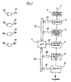
- the broadband amplifier 2 serves to raise the signal level, the signals incident on the antenna 1 from the transmitting antennas 11 of the consumption distribution devices 1o.
- the broadband amplifier 2 preferably has a nonlinear, in particular quadratic, characteristic curve in order to favor the incoming signals of the consumption distribution device 10 over the general interference level.
- the scanner 3 causes a continuous narrow band (df) scanning the pass band (Df) of the broadband amplifier 2 and thereby achieves an interference reduction of the Broadband range of the amplifier 2.
- the scanner 3 will advantageously controlled by a microprocessor 5, which is the 1, which the receiver circuit 6th together with the calculator 7 to 9, is common.
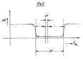
- the receiver circuit 6 includes the broadband amplifier as well 2 a broadband (Df) input circuit, which has a damping characteristic according to Figure 2 and the a super heterodyne circuit for frequency demodulation is subordinate.
- Df broadband
- the evaluation circuit 7 downstream of the receiver circuit 6 deals with the storage, control and evaluation of the from the consumption distribution devices 1o via their Antennas 11 transmit measured value telegrams on the radio path.
- All of the individual consumption distribution devices 1o 1 via their antennas 11 broadcast or UHF signals transmitted are received by the receiving antenna 1 detected and corrected by the scanner 3, the receiver circuit 6 forwarded.
- the course of the input attenuation is shown schematically in FIG the broadband amplifier 2 and the receiver circuit 6 shown within the frequency range Df.
- This Frequency range Df gives the range of the frequency band of the oscillators controlled by SAW components UHF transmitter (1o) again.
- the scanner 3 provides a narrow band, the frequency range df comprehensive input of the particular as Superheterodyne trained receiving circuit that with controlled variable tuning, such that the cut frequency range df in the broadband range Df scans back and forth.
- This scattering range Df of the SAW resonators of the transmitter circuits is mainly used for heat cost and hot water cost allocators significant because of the possible high levels that occur here Temperature fluctuations.
- the SAW resonators are inherently quite constant in frequency, in those occurring in the aforementioned applications however, high possible temperature differences are certain Frequency fluctuations of those equipped with SAW resonators UHF transmitter circuits cannot be completely avoided.
- This comparatively broadband passband (Df) is now continuously scanned for signal incidence by the appropriately dimensioned and designed scanner 3 in narrowband (df). This ensures that continuous and interference-reducing, narrow-band monitoring takes place within the pass band (Df) of the inputs of the amplifier 2 and the receiver circuit 6, which corresponds approximately to the scattering range of the SAW resonators of the UHF transmitter circuits (1o).
- Scanner 3 and receiver circuit 6 are always absolutely common in function.
- the width of the pass band (Df) of the inputs of the broadband amplifier (2) or the receiver circuit (6) is determined by the amount the maximum possible frequency deviation of the SAW resonator (10) determined by the setpoint.
Landscapes
- Physics & Mathematics (AREA)
- General Physics & Mathematics (AREA)
- Arrangements For Transmission Of Measured Signals (AREA)
- Surface Acoustic Wave Elements And Circuit Networks Thereof (AREA)
Description
wobei einer jeden Meßstelle eine elektronische Verbrauchsverteilereinrichtung zugeordnet ist, die einen relativen oder absoluten Verbrauchswert an der betreffenden Meßstelle erarbeitet, aufsummiert und elektronisch speichert,
und der elektronischen Verbrauchsverteilereinrichtung ein elektronischer Parallel-Serienwandler zugeordnet ist, welcher den elektronisch festgehaltenen und codierten Verbrauchswert in eine sequentielle Impulsfolge umwandelt,
wobei der Verbrauchsverteilereinrichtung außerdem ein elektromagnetische Wellen abstrahlender Sender zugeordnet ist,
der von dem Parallel-Serienwandler im Rhythmus der von letzterem verabfolgten sequentiellen Impulsfolge geschaltet wird, und wobei die elektronische Sendeschaltung ein akustisches Oberflächenwellenelement als Frequenz-Resonator aufweist,
und der zentralen Empfangsstelle ein elektromagnetische Wellen selektierender und aufnehmender Empfänger zugeordnet ist, der die übermittelten elektromagnetischen sequentiellen Impulssignale in die zentrale Empfangsstelle überträgt.
Dies hat zur Folge, daß eintreffende Meßsignale durch die Prüfschaltung der dem Empfänger zugeordneten Zentralstelle nur bedingt als richtig erkannt werden können. Es wird von Fall zu Fall der Empfang mehrerer Signalfolgen und deren Überprüfung notwendig werden, um die gezielte Ablesung einer bestimmten Verbrauchsverteilereinrichtung vornehmen zu können. Die Betriebssicherheit der Signalübertragung ist somit durch den erforderlichen breitbandigen Eingang des Empfängers gemindert.
- Figur 1
- eine schematische Darstellung der der Erfindung zugrunde liegenden Meßeinrichtung für Verbrauchskosten;
- Figur 2
- eine graphische Darstellung des Dämpfungsverlaufes im Eingang der Empfängerschaltung bzw. des Breitbandverstärkers.
Der Breitbandverstärker 2 hat vorzugsweise eine nichtlineare, insbesondere quadratische Kennlinie, um die einfallenden Signale der Verbrauchsverteilereinrichtung 1o gegenüber dem allgemeinen Störpegel zu begünstigen.
Es ist so sichergestellt, daß innerhalb des Durchlaßbereiches (Df) der Eingänge des Verstärkers 2 und der Empfängerschaltung 6, welcher ja etwa dem Streubereich der OFW-Resonatoren der UHF-Senderschaltungen (1o) entspricht, eine stetige und störungsmindernde, schmalbandige Überwachung stattfindet.
Claims (6)
- Anlage zur zentralen Erfassung von Energieverbrauchskosten, so Heizungs- und Warmwasserkosten in Wohn- und/oder Geschäftsräumen, wobei die einzelnen Verbrauchsstellen durch Übermittlung von codierten Signalen die jeweilige Meßstelle, den jeweils aufgelaufenen Verbrauchswert und ggf. weitere kennzeichnenden Daten an eine zentrale Empfangsstelle melden,
bei welcher die übermittelten Daten der einzelnen Meßstellen zentral erfaßt und ggf.
der Abrechnung zugeführt werden,
wobei einer jeden Meßstelle eine elektronische Verbrauchsverteilereinrichtung (1o) zugeordnet ist,
die einen relativen oder absoluten Verbrauchswert an der betreffenden Meßstelle erarbeitet, aufsummiert und elektronisch speichert,
und der elektronischen Verbrauchsverteilereinrichtung (1o) ein elektronischer Parallel-Serienwandler zugeordnet ist, welcher den elektronisch festgehaltenen und codierten Verbrauchswert in eine sequentielle Impulsfolge umwandelt,
wobei der Verbrauchsverteilereinrichtung (1o) außerdem ein elektromagnetische Wellen abstrahlender Sender zugeordnet ist,
der von dem Parallel-Serienwandler im Rhythmus der von letzterem verabfolgten sequentiellen Impulsfolge geschaltet wird, und wobei die elektronische Sendeschaltung ein akustisches Oberflächenwellenelement als Frequenz-Resonator aufweist,
und der zentralen Empfangsstelle ein elektromagnetische Wellen selektierender und aufnehmender Empfänger (6) zugeordnet ist, der die übermittelten elektromagnetischen sequentiellen Impulssignale in die zentrale Empfangsstelle überträgt,
dadurch gekennzeichnet,
daß der Empfänger eine Empfängerschaltung (6) mit breitbandigem Eingang (Df) enthält, der eine schmalbandig (df) wirkende Scanner-Schaltung vorgeschaltet ist, wobei die Eingangsbandbreite der Empfängerschaltung die Streubreite der durch die Oberflächenwellen-Elemente bestimmten Sendefrequenzen der Verbrauchsverteilereinrichtungen umfaßt,
und wobei der durch die Scanner-Schaltung angeschnittene Frequenzbereich in diesem Breitbandbereich Df abtastend hin- und herwandert. - Anlage nach Anspruch 1,
dadurch gekennzeichnet,
daß die Scanner-Schaltung (3) zwingend zusammen mit der Empfängerschaltung (6) wirksam ist und nur zusammen mit dieser (6) ein- und ausschaltbar ist. - Anlage nach Anspruch 1 oder 2,
dadurch gekennzeichnet,
daß der Scanner-Schaltung (3) ein UHF-Breitbandverstärker (2) zugeordnet ist. - Anlage nach Anspruch 3,
dadurch gekennzeichnet,
daß der UHF-Breitbandverstärker (2) eine nichtlineare Verstärkerkennlinie aufweist. - Anlage nach Anspruch 4,
dadurch gekennzeichnet,
daß die Verstärkerkennlinie etwa quadratisch ist. - Anlage nach einem der Ansprüche 1 - 5,
dadurch gekennzeichnet,
daß die Breite des Durchlaßbereiches (Df) der Eingänge des Breitbandverstärkers (2) bzw. der Empfängerschaltung (6) durch den Betrag der maximal möglichen Frequenzabweichung des OFW-Resonators vom Sollwert bestimmt ist.
Applications Claiming Priority (2)
| Application Number | Priority Date | Filing Date | Title |
|---|---|---|---|
| DE4312596 | 1993-04-17 | ||
| DE19934312596 DE4312596A1 (de) | 1993-04-17 | 1993-04-17 | Anlage zur zentralen Erfassung von Energieverbrauchskosten |
Publications (2)
| Publication Number | Publication Date |
|---|---|
| EP0627716A1 EP0627716A1 (de) | 1994-12-07 |
| EP0627716B1 true EP0627716B1 (de) | 2000-03-01 |
Family
ID=6485719
Family Applications (1)
| Application Number | Title | Priority Date | Filing Date |
|---|---|---|---|
| EP19940106017 Expired - Lifetime EP0627716B1 (de) | 1993-04-17 | 1994-04-18 | Anlage zur zentralen Erfassung von Energieverbrauchskosten |
Country Status (2)
| Country | Link |
|---|---|
| EP (1) | EP0627716B1 (de) |
| DE (1) | DE4312596A1 (de) |
Cited By (1)
| Publication number | Priority date | Publication date | Assignee | Title |
|---|---|---|---|---|
| US9614553B2 (en) | 2000-05-24 | 2017-04-04 | Enocean Gmbh | Energy self-sufficient radiofrequency transmitter |
Families Citing this family (6)
| Publication number | Priority date | Publication date | Assignee | Title |
|---|---|---|---|---|
| PT960410E (pt) | 1997-02-12 | 2002-04-29 | Siemens Ag | Dispositivo e processo para a producao de sinais codificados de alta frequencia |
| DE29710248U1 (de) * | 1997-06-12 | 1998-10-15 | Raab Karcher Energy Services GmbH, 45131 Essen | Vorrichtung zur Wärmeverbrauchserfassung und zur Regelung der Heizleistung eines einzelnen Heizkörpers für die Raumtemperaturregelung |
| DE19745973C2 (de) * | 1997-10-17 | 2000-06-29 | Schwenk Kg Theben Werk | Funkgesteuerter Heizungsregler |
| DE19751214A1 (de) * | 1997-11-19 | 1999-06-10 | Raab Karcher Energy Services G | Verfahren zur Erfassung und Auswertung von temperaturabhängigen Verbrauchswerten oder Meßwerten anderer physikalischer Größen |
| NO322272B1 (no) | 1999-03-26 | 2006-09-04 | Kongsberg Maritime As | Sensor og system for overvaking av temperatur inne i vanskelig tilgjengelige, bevegelige deler |
| DE10150128C2 (de) | 2001-10-11 | 2003-10-02 | Enocean Gmbh | Drahtloses Sensorsystem |
Family Cites Families (3)
| Publication number | Priority date | Publication date | Assignee | Title |
|---|---|---|---|---|
| US3949312A (en) * | 1974-09-16 | 1976-04-06 | American Electronic Laboratories, Inc. | Frequency scanning means and method |
| US5056107A (en) * | 1990-02-15 | 1991-10-08 | Iris Systems Inc. | Radio communication network for remote data generating stations |
| GB9118030D0 (en) * | 1991-08-21 | 1991-10-09 | Disys Inc | Data gathering system |
-
1993
- 1993-04-17 DE DE19934312596 patent/DE4312596A1/de not_active Withdrawn
-
1994
- 1994-04-18 EP EP19940106017 patent/EP0627716B1/de not_active Expired - Lifetime
Cited By (2)
| Publication number | Priority date | Publication date | Assignee | Title |
|---|---|---|---|---|
| US9614553B2 (en) | 2000-05-24 | 2017-04-04 | Enocean Gmbh | Energy self-sufficient radiofrequency transmitter |
| US9887711B2 (en) | 2000-05-24 | 2018-02-06 | Enocean Gmbh | Energy self-sufficient radiofrequency transmitter |
Also Published As
| Publication number | Publication date |
|---|---|
| EP0627716A1 (de) | 1994-12-07 |
| DE4312596A1 (de) | 1994-10-20 |
Similar Documents
| Publication | Publication Date | Title |
|---|---|---|
| DE2755867C2 (de) | Frequenzumsetzeranordnung bei einem Sende-Empfangsgerät | |
| EP0740799A1 (de) | Verfahren und vorrichtung zur erfassung lebender körper | |
| EP2101278A2 (de) | Kompensationsschaltung für eine RFID-Readereinheit und RFID-Readereinheit | |
| DE2544693A1 (de) | Verbesserte unempfindlichkeit gegenueber frequenzselektiver daempfung aufweisendes, digitales datenuebertragungssystem | |
| DE69027922T2 (de) | Transpondersystem | |
| DE102007023698A1 (de) | Sensor zur Abstandsmessung und Verfahren zur Abstandsmessung unter Verwendung des Sensors | |
| EP1325289A1 (de) | Füllstandsmessgerät | |
| DE2803608C2 (de) | Vierpolmeßverfahren und Schaltungsanordnung zu dessen Durchführung | |
| DE4409803A1 (de) | Anlage zur zentralen Erfassung von Energieverbrauchskosten | |
| EP0627716A1 (de) | Anlage zur zentralen Erfassung von Energieverbrauchskosten | |
| DE3888993T2 (de) | Vorrichtung zur Überwachung der Radarleistungsfähigkeit. | |
| EP0602370A1 (de) | Rundfunkempfänger | |
| DE102005061523A1 (de) | Datentransmitter und Datentransceiver mit einem SAW-Filter | |
| DE4420448C1 (de) | Verfahren und Vorrichtung zur Messung der Feldstärke in einem Funkkanal und dessen Nachbarkanälen mittels Zero-IF | |
| DE4027972A1 (de) | Vorrichtung und verfahren zur telemetrischen bestimmung einer entfernung und anwendung bei einer radarsonde fuer die bestimmung der topographischen karte der begichtungsoberflaeche in einem schachtofen | |
| CH694672A5 (de) | System mit einem Interrogations- und Respondersystem. | |
| DE102012218730A1 (de) | Verstärkungsgrad-Messchaltung, Verstärkungsgrad-Messverfahren und Kommunikationsgerät | |
| DE69830181T2 (de) | Schwundmarginmessung eines funksystems | |
| DE2938968A1 (de) | Alarmsystem fuer den schutz von glasflaechen, insbesondere schaufensterscheiben | |
| EP2360484B1 (de) | Bidirektionales Funk-Datenübertragungsverfahren | |
| DE3510137C2 (de) | Überwachungseinrichtung für TACAN-Funkfeuer | |
| DE202014008974U1 (de) | Hochfrequenzmesssystem zum Messen des Feuchtigkeitsgehalts von Papier und verschiedenen faserhaltigen Materialien | |
| DE2059263C3 (de) | Anordnung zur Fernübertragung bzw. Fernanzeige der Untersuchungswerte zu untersuchender Personen | |
| DE3618170C2 (de) | ||
| DE1957303C3 (de) | Sekundärradar-Abfrage-Antwort-System mit Zusatzantenne zur Nebenkeulenabfrageunterdrückung |
Legal Events
| Date | Code | Title | Description |
|---|---|---|---|
| PUAI | Public reference made under article 153(3) epc to a published international application that has entered the european phase |
Free format text: ORIGINAL CODE: 0009012 |
|
| AK | Designated contracting states |
Kind code of ref document: A1 Designated state(s): CH FR LI NL |
|
| 17P | Request for examination filed |
Effective date: 19950607 |
|
| 17Q | First examination report despatched |
Effective date: 19971013 |
|
| GRAG | Despatch of communication of intention to grant |
Free format text: ORIGINAL CODE: EPIDOS AGRA |
|
| GRAG | Despatch of communication of intention to grant |
Free format text: ORIGINAL CODE: EPIDOS AGRA |
|
| GRAH | Despatch of communication of intention to grant a patent |
Free format text: ORIGINAL CODE: EPIDOS IGRA |
|
| GRAH | Despatch of communication of intention to grant a patent |
Free format text: ORIGINAL CODE: EPIDOS IGRA |
|
| GRAA | (expected) grant |
Free format text: ORIGINAL CODE: 0009210 |
|
| AK | Designated contracting states |
Kind code of ref document: B1 Designated state(s): CH FR LI NL |
|
| REG | Reference to a national code |
Ref country code: CH Ref legal event code: EP |
|
| ET | Fr: translation filed | ||
| PLBE | No opposition filed within time limit |
Free format text: ORIGINAL CODE: 0009261 |
|
| STAA | Information on the status of an ep patent application or granted ep patent |
Free format text: STATUS: NO OPPOSITION FILED WITHIN TIME LIMIT |
|
| 26N | No opposition filed | ||
| PGFP | Annual fee paid to national office [announced via postgrant information from national office to epo] |
Ref country code: NL Payment date: 20011031 Year of fee payment: 8 |
|
| PGFP | Annual fee paid to national office [announced via postgrant information from national office to epo] |
Ref country code: FR Payment date: 20020429 Year of fee payment: 9 |
|
| PGFP | Annual fee paid to national office [announced via postgrant information from national office to epo] |
Ref country code: CH Payment date: 20020430 Year of fee payment: 9 |
|
| PG25 | Lapsed in a contracting state [announced via postgrant information from national office to epo] |
Ref country code: NL Free format text: LAPSE BECAUSE OF NON-PAYMENT OF DUE FEES Effective date: 20021101 |
|
| NLV4 | Nl: lapsed or anulled due to non-payment of the annual fee |
Effective date: 20021101 |
|
| PG25 | Lapsed in a contracting state [announced via postgrant information from national office to epo] |
Ref country code: LI Free format text: LAPSE BECAUSE OF NON-PAYMENT OF DUE FEES Effective date: 20030430 Ref country code: CH Free format text: LAPSE BECAUSE OF NON-PAYMENT OF DUE FEES Effective date: 20030430 |
|
| REG | Reference to a national code |
Ref country code: CH Ref legal event code: PL |
|
| PG25 | Lapsed in a contracting state [announced via postgrant information from national office to epo] |
Ref country code: FR Free format text: LAPSE BECAUSE OF NON-PAYMENT OF DUE FEES Effective date: 20031231 |
|
| REG | Reference to a national code |
Ref country code: FR Ref legal event code: ST |