EP0626824B1 - Vorrichtung für transanale resektatextraktionen - Google Patents
Vorrichtung für transanale resektatextraktionen Download PDFInfo
- Publication number
- EP0626824B1 EP0626824B1 EP93903169A EP93903169A EP0626824B1 EP 0626824 B1 EP0626824 B1 EP 0626824B1 EP 93903169 A EP93903169 A EP 93903169A EP 93903169 A EP93903169 A EP 93903169A EP 0626824 B1 EP0626824 B1 EP 0626824B1
- Authority
- EP
- European Patent Office
- Prior art keywords
- sleeve
- rectoscope
- piece
- tubular
- extractor
- Prior art date
- Legal status (The legal status is an assumption and is not a legal conclusion. Google has not performed a legal analysis and makes no representation as to the accuracy of the status listed.)
- Expired - Lifetime
Links
Images
Classifications
-
- A—HUMAN NECESSITIES
- A61—MEDICAL OR VETERINARY SCIENCE; HYGIENE
- A61B—DIAGNOSIS; SURGERY; IDENTIFICATION
- A61B17/00—Surgical instruments, devices or methods, e.g. tourniquets
- A61B17/28—Surgical forceps
- A61B17/29—Forceps for use in minimally invasive surgery
-
- A—HUMAN NECESSITIES
- A61—MEDICAL OR VETERINARY SCIENCE; HYGIENE
- A61B—DIAGNOSIS; SURGERY; IDENTIFICATION
- A61B17/00—Surgical instruments, devices or methods, e.g. tourniquets
- A61B17/00234—Surgical instruments, devices or methods, e.g. tourniquets for minimally invasive surgery
-
- A—HUMAN NECESSITIES
- A61—MEDICAL OR VETERINARY SCIENCE; HYGIENE
- A61B—DIAGNOSIS; SURGERY; IDENTIFICATION
- A61B17/00—Surgical instruments, devices or methods, e.g. tourniquets
- A61B17/34—Trocars; Puncturing needles
- A61B17/3403—Needle locating or guiding means
Definitions
- the invention relates to a device for transanal resect extraction according to the preamble of the first claim.
- Neoplasias new tissue formation such as tumors
- angiodysplasias vascular malformations
- the intestine is cut in front of and behind the sigma using laparoskopiam with the help of optical and surgical instruments inserted through the abdominal wall.
- the resect must be removed before the descending colon and rectum can be connected. The resect is extracted through the anus.
- a rectoscope sleeve is usually inserted transanorectally and the proximal end (facing the surgeon) is closed with a connector.
- Rectoscope sleeves with an outer diameter of 40 mm and various lengths are commercially available.
- the known rectoscope sleeves are chamfered at their distal end (facing away from the surgeon). They are inserted using a so-called stylet (a rod with a thickening in the form of a cone or a rounded cylinder at the distal end, the diameter of which is slightly smaller than the inside diameter of the rectoscope sleeve).
- the connector of the rectoscope sleeve contains a pipe socket through which carbon dioxide can be introduced in order to expand the intestine.
- a grasping forceps is pushed through the rectoscope sleeve into the rectum through an opening in the connector.
- the laparoscopist transfers the resectate to the forceps, which are used to remove it transanal through the rectoscope sleeve.
- Such a rectoscope sleeve with connecting piece is shown in a figure of DE 33 29 784 C2. Furthermore, grasping forceps are indicated, which are inserted through the connector into the rectoscope sleeve.
- DE 38 23 604 A1 discloses a device for intracavitary radiation therapy of malignant rectal tumors.
- the known device has a tube, which corresponds to a rectoscope sleeve, and an endostat, which consists of a hollow tube and a club-shaped thickening.
- the club-shaped thickening is hollowed out so that radioactive material can be brought to the treatment site.
- a rectoscope is known from DE 82 33 240 U1, which contains a short, wide tube and a rotatable coupling ring.
- a stylet is passed through the tube.
- an instrument carrier is placed on the tube as a connector via a bayonet-type closure. The closure is brought about by the engagement of locking balls in an annular groove.
- the object of the invention is to propose an improved device with which an intestinal section can be extracted transanal and in which the risk of lesions or perforations is at least greatly reduced. Another object is to design the device so that a quick and easy operation by the surgeon is possible.
- the device according to the invention essentially consists of three components: a rectoscope sleeve 1, a connecting piece 2 and a resect extractor 3.
- a tube can be used as the rectoscope sleeve 1, the diameter of which is adapted to the diameter of the anus.
- the length of the rectoscope sleeve without end piece 4 is generally chosen in accordance with the length of the rectum (approx. 15 to 20 cm).
- the distal end of the rectoscope sleeve is preferably designed in the form of a bead.
- a rotationally symmetrical embodiment of the rectoscope sleeve appears more suitable than the known rectoscope sleeves.
- the rectoscope sleeve can also be distally beveled in the known manner.
- the proximal end of the rectoscope sleeve is formed by the tubular end piece 4.
- the outer diameter of the end piece is preferably larger than the outer diameter of the actual rectoscope sleeve, in order to create more space for the hole which receives the resectate extractor 3, for further holes and for the devices to be inserted through the holes (gripping tongs, viewing devices etc.).
- One of the further bores can accommodate an optical control device in a known manner.
- the gas inlet connector 18 is preferably provided on the end piece 4 of the rectoscope sleeve 1; this makes it easier to attach and remove the connector, because in this case it does not depend on the insufflation line.
- the gas inlet connector 18 is designed as a handle, for example in the form of a corrugated sleeve. Such a handle can also be used during the operation if necessary.
- the rectoscope sleeve 1 With the connector 2, the rectoscope sleeve 1 can be closed tightly at its end piece 4. A tight seal is required to prevent the gas (carbon dioxide) introduced during the operation from escaping in an uncontrolled manner.
- the connector 2 preferably consists of a cylinder 5 and a U-shaped clamping device 6.
- the cylinder 5 is preferably axially pierced.
- the clamping device 6 encompasses the bore.
- a guide tube 19 is attached to the distal side of the cylinder 5 in an axially symmetrical manner.
- a particularly preferred embodiment of this guide tube is that its length is so is chosen that it extends through the end piece 4 into the tubular region of the rectoscope sleeve. Tilting of the connector 2 can thus be avoided.
- Fig. 4 shows such an embodiment of the connector 2.
- the guide tube 19 contains openings which are arranged such that when the connector 2 is firmly connected to the rectoscope sleeve 1, the outlet of the gas inlet connector 18 remains open.
- the rectoscope sleeve 1 and the connector 2 are preferably connected to one another with the aid of a bayonet catch.
- at least two, preferably three pins 11 are attached to the lateral surface of the cylinder 5, which engage in a corresponding number of angled recesses 9 on the edge of the end piece 4.
- Resilient webs 10 are formed on the edge of the end piece 4 through the cutouts 9.
- the resilient webs 10 can have a small recess of approximately 0.1 mm at one point and then have a stop, through which a clear locking position of the pins is defined. This is particularly recommended when the guide tube 19 is designed in the manner shown in FIG. 4 so that one of the openings 20 is aligned with the gas inlet connection.
- the resect extractor represents the essential part of the device according to the invention.
- the resect extractor has the task of guiding the grasping forceps with which the resect is grasped and positioning it in the correct place. It is advanced anorectally until its distal end emerges from the end of the remaining section of the intestine. According to the invention, this end is shaped in such a way that traumatization, in particular lesions or perforations of the intestinal wall, can be avoided when the rectum is pushed forward.
- the grasping forceps in the known devices without a resectate extractor through an opening of the connector pushed into the rectoscope sleeve and through it into the intestine.
- the end of grasping forceps can only be designed atraumatically to a limited extent, because it must be able to be pushed through an opening in the connecting piece without substantial play in such a way that the opening is sealed.
- the movable parts of the grasping forceps must remain free at the distal end, so that the surgeon requires considerable skill to advance such an instrument to the desired location without injuring the intestinal wall.
- the resect extractor can be designed in such a way that the surface pressure between the instrument and intestinal wall, which ultimately leads to perforation of the intestine if the values are too high, is reduced to uncritical values and the safe sliding over of intestinal irregularities is facilitated.
- the burden on the intestinal wall during this process can be further reduced by increasing the CO 2 pressure in the rectoscope sleeve via the gas connecting piece 18 to slightly above the pneumoperitoneum pressure in order to widen the rectum and partially lift it off the outer surface of the protector section.
- the grasping forceps are advanced through the tube section and the protector section of the resect extractor to the abdomen and are used to grasp the resect.
- both the grasping forceps and the resectate extractor are withdrawn.
- the resect is removed from the rectoscope sleeve as usual by removing the connector.
- the resect extractor consists of a tube section 7 and a thickened, pierced section at the distal end.
- the section at the distal end is widened in the shape of a club.
- the pipe section passes over a transition region 13 into a substantially cylindrical region 14 with a larger outer diameter, which is defined by a dome-shaped, for. B.
- hemispherical protector area 15 is completed with an opening at the distal end.
- This embodiment is optimized in a special way with regard to the lowest possible surface pressure.
- the length of the transition region 13 and the cylindrical region 14 and the opening angle of the transition region are chosen so that a body that is as aerodynamic as possible is created.
- the length of the three areas 13, 14, 15 should be shorter than the length of the rectoscope sleeve, so that the resectate can be withdrawn in its area. If necessary, it is also possible to dispense with the cylindrical region 14 or to design the protector region as a paraboloid.
- the second embodiment is proposed for the resection of infectious or degenerate tissue.
- the tube section 7 can be widened in a funnel shape at the distal end of the resect extractor.
- the funnel-shaped extension in the transition region 13 can be followed by a cylindrical region 16, in which both the outside and the inside diameter are enlarged relative to the pipe section 7.
- the distal The edge of this resect extractor is atraumatically shaped by a thickened and drawn-in bead.
- the operation of the device according to the invention is made considerably easier if a displaceable clamping device 12 is pushed onto the tube section 7 of the resect extractor 3 lying outside the rectoscope sleeve.
- Both the clamping device 6 attached to the connecting piece 2 and the clamping device 12 which can be moved on the pipe section 7 are preferably constructed in the same way.
- a particularly simple operation is achieved with such clamping devices in which a U-shaped part surrounds the pipe section 7, the legs of this part being pierced. A thread is cut into one of the holes. A screw engages through one of the holes in the threaded hole.
- the shaft of this screw is designed as a handle.
- a handle in the form of a sleeve is particularly preferred, the outside of which is corrugated. As a result, weight can be saved to a considerable extent.
- One-hand operation is possible with such a clamping device.
- the proximal end of the resect extractor can then be closed by a plug 21 with a silicone grommet when the grasping forceps are not inserted. Otherwise, the resected extractor is sealed by the grasping forceps themselves or by sealing elements attached to them.
- a stainless steel is particularly suitable as the material for the device according to the invention.
- the entire device simply sterilized using disposable items for any necessary sealing aids.
- the protector section of the resected extractor can also consist of polytetrafluoroethylene (PTFE), as shown in FIG. 1.
- PTFE polytetrafluoroethylene
- FIG. 1 PTFE is tissue-friendly, water-repellent and can also be sterilized at high temperatures.
- the device according to the invention or individual parts thereof such as. B. the resect extractor in an injection molding process from a plastic and destroy after use.
Description
- Die Erfindung betrifft eine Vorrichtung für transanale Resektatextraktionen gemäß dem Oberbegriff des ersten Patentanspruchs.
- Neoplasien (Neubildung von Gewebe wie z. B. Tumore) und Angiodysplasien (Gefäßfehlbildungen) im Sigma können eine Resektion dieses Darmteils zwischen Colon descendens und Rektum erforderlich machen. Bei dieser Resektion wird der Darm vor und hinter dem Sigma per laparoskopiam mit Hilfe von durch die Bauchdecke eingeführten optischen und chirurgischen Instrumenten durchtrennt. Bevor das Colon descendens und das Rektum miteinander verbunden werden können, muß das Resektat entfernt werden. Die Extraktion des Resektats erfolgt durch den Anus.
- Zur Extraktion des Resektats wird üblicherweise eine Rektoskop-Hülse transanorektal eingeführt und das proximale (dem Operateur zugewandte) Ende mit einem Anschlußstück verschlossen. Rektoskop-Hülsen mit einem äußeren Durchmesser von 40 mm und verschiedener Länge sind kommerziell erhältlich. Die bekannten Rektoskop-Hülsen sind an ihrem distalen (dem Operateur abgewandten) Ende angeschrägt. Sie werden mit Hilfe eines sogenannten Mandrins (eines Stabes mit einer Verdickung in Form eines Konus oder eines abgerundeten Zylinders am distalen Ende, deren Durchmesser etwas kleiner ist als der Innendurchmesser der Rektoskop-Hülse) eingeführt. Das Anschlußstück der Rektoskop-Hülse enthält einen Rohrstutzen, durch den Kohlendioxid eingeleitet werden kann, um den Darm aufzuweiten. Durch eine Öffnung im Anschlußstück wird eine Faßzange durch die Rektoskop-Hülse in das Rektum vorgeschoben. Der Laparoskopiker übergibt das Resektat an die Faßzange, mit deren Hilfe es durch die Rektoskop-Hülse transanal entfernt wird.
- In einer Figur der DE 33 29 784 C2 ist eine solche Rektoskop-Hülse mit Anschlußstück dargestellt. Weiterhin ist eine Faßzange angedeutet, die durch das Anschlußstück in die Rektoskop-Hülse eingeschoben ist.
- Beim transanorektalen Einschieben der Faßzange in das Abdomen sind bei dem beschriebenen Vorgehen - abhängig von der Anatomie und Histologie des Darmteils, der nicht durch die Rektoskop-Hülse geschützt ist, von der Übung und Erfahrung des Chirurgen und von der Ausführung der Faßzange - Läsionen und/oder Perforationen nicht auszuschließen.
- Aus der DE 38 23 604 A1 ist eine Einrichtung zur intrakavitären Strahlentherapie von bösartigen Mastdarmgeschwulsten bekannt.
- Die bekannte Vorrichtung weist einen Tubus auf, der einer Rektoskop-Hülse entspricht, und einen Endostat, der aus einem Hohlrohr und einer keulenförmigen Verdickung besteht. Die keulenförmige Verdickung ist ausgehöhlt, so daß radioaktives Material an die Behandlungsstelle gebracht werden kann.
- Ferner ist aus der DE 82 33 240 U1 ein Rektoskop bekannt, das einen kurzen, weiten Tubus und einen verdrehbaren Kupplungsring enthält. Durch den Tubus wird ein Mandrin geführt. Nach dem Entfernen des Mandrins wird ein Instrumententräger als Anschlußstück über einen bajonettartigen Verschluß auf den Tubus aufgesetzt. Der Verschluß wird durch das Eingreifen von Sperrkugeln in eine Ringnut bewirkt.
- Aufgabe der Erfindung ist, eine verbesserte Vorrichtung vorzuschlagen, mit der ein Darmabschnitt transanal extrahiert werden kann und bei der die Gefahr von Läsionen oder Perforationen zumindest stark vermindert ist. Eine weitere Aufgabe besteht darin, die Vorrichtung so auszugestalten, daß eine schnelle und einfache Bedienung durch den Operateur möglich ist.
- Die Aufgabe wird bei einer Vorrichtung der eingangs genannten Art erfindungsgemäß durch das im ersten Patentanspruch gekennzeichnete Merkmal gelöst. Die weiteren Ansprüche beschreiben vorteilhafte Ausführungsformen der erfindungsgemäßen Vorrichtung.
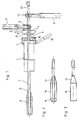
- Die erfindungsgemäße Vorrichtung wird im folgenden anhand der Fig. 1 bis 4 näher erläutert.
- Fig. 1 stellt eine Ausführungsform der erfindungsgemäßen Vorrichtung dar.
- Fig. 2 zeigt eine Ausführungsform des Resektatextraktors.
- Fig. 3 zeigt eine weitere Ausführungsform des Resektatextraktors.
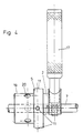
- Fig. 4 stellt eine vorteilhafte Ausführungsform des Anschlußstücks dar.
- Die erfindungsgemäße Vorrichtung besteht im wesentlichen aus drei Komponenten: einer Rektoskop-Hülse 1, einem Anschlußstück 2 und einem Resektatextraktor 3.
- Als Rektoskop-Hülse 1 kann ein Rohr verwendet werden, dessen Durchmesser an den Durchmesser des Anus angepaßt ist. Die Länge der Rektoskop-Hülse ohne Endstück 4 wird im allgemeinen entsprechend der Länge des Rektums (ca. 15 bis 20 cm) gewählt. Um eine Traumatisierung der Rektuminnenwand beim Einführen zu vermeiden, wird das distale Ende der Rektoskop-Hülse vorzugsweise in Form eines Wulstes ausgebildet. Aus dem selben Grund erscheint eine rotationssymmetrische Ausführungsform der Rektoskop-Hülse besser geeignet als die bekannten Rektoskop-Hülsen. Jedoch kann die Rektoskop-Hülse auch in der bekannten Weise distal abgeschrägt sein.
- Das proximale Ende der Rektoskop-Hülse wird durch das rohrförmige Endstück 4 gebildet. Der Außendurchmesser des Endstücks ist vorzugsweise größer als der Außendurchmesser der eigentlichen Rektoskop-Hülse, um mehr Platz für die Bohrung, die den Resektatextraktor 3 aufnimmt, für weitere Bohrungen und für die durch die Bohrungen einzuführenden Geräte (Faßzangen, Sichtgeräte etc.) zu schaffen. Eine der weiteren Bohrungen kann in bekannter Weise eine optische Kontrolleinrichtung aufnehmen.
- Vorzugsweise wird der Gaseinlaßstutzen 18 am Endstück 4 der Rektoskop-Hülse 1 vorgesehen; hierdurch wird das Ansetzen und Abnehmen des Anschlußstücks erleichtert, denn es hängt in diesem Fall nicht an der Insufflationsleitung. Besonders bevorzugt wird eine solche Ausführungsform, bei der der Gaseinlaßstutzen 18 als Handgriff, etwa in Form einer geriffelten Hülse ausgebildet ist. Ein solcher Handgriff läßt sich während der Operation bei Bedarf auch z. B. über einen einstellbaren Gelenkarm fest mit dem Operationstisch verbinden.
- Mit dem Anschlußstück 2 läßt sich die Rektoskop-Hülse 1 an ihrem Endstück 4 dicht verschließen. Ein dichter Verschluß ist erforderlich, um zu verhindern, daß das während der Operation eingeleitete Gas (Kohlendioxid) unkontrolliert entweicht.
- Das Anschlußstück 2 besteht vorzugsweise aus einem Zylinder 5 und einer U-förmigen Klemmvorrichtung 6. Der Zylinder 5 ist vorzugsweise axial durchbohrt. Die Klemmvorrichtung 6 umgreift die Bohrung. Um das Anschlußstück 2 leicht und ohne Verkanten auf das Endstück 4 der Rektoskop-Hülse 1 aufsetzen zu können, ist auf der distalen Seite des Zylinders 5 axialsymmetrisch ein Führungsrohr 19 angebracht. Eine besonders bevorzugte Ausführung dieses Führungsrohrs besteht darin, daß seine Länge so gewählt ist, daß es durch das Endstück 4 bis in den rohrförmigen Bereich der Rektoskop-Hülse reicht. Damit kann ein Verkanten des Anschlußstücks 2 vermieden werden. Fig. 4 zeigt eine solche Ausführungsform des Anschlußstücks 2. Das Führungsrohr 19 enthält Öffnungen, die in der Weise angeordnet sind, daß dann, wenn das Anschlußstück 2 fest mit der Rektoskop-Hülse 1 verbunden ist, der Ausgang des Gaseinleitungsstutzens 18 offen bleibt.
- Vorzugsweise werden die Rektoskop-Hülse 1 und das Anschlußstück 2 mit Hilfe eines Bajonettverschlusses miteinander verbunden. In dieser Ausführungsform sind auf der Mantelfläche des Zylinders 5 mindestens zwei, vorzugsweise drei Stifte 11 angebracht, die in entsprechend viele abgewinkelte Aussparungen 9 am Rand des Endstücks 4 eingreifen. Durch die Aussparungen 9 werden federnde Stege 10 am Rand des Endstücks 4 ausgebildet. Die federnden Stege 10 können an einer Stelle eine kleine Ausnehmung von etwa 0,1 mm und daran anschließend einen Anschlag aufweisen, durch die eine eindeutige Verschlußposition der Stifte definiert wird. Dies empfiehlt sich vor allem dann, wenn das Führungsrohr 19 in der in Fig. 4 dargestellten Art ausgebildet ist, damit eine der Öffnungen 20 mit dem Gaseinleitungsstutzen fluchtet.
- Den wesentlichen Teil der erfindungsgemäßen Vorrichtung stellt der Resektatextraktor dar. Der Resektatextraktor hat die Aufgabe, die Faßzange, mit der das Resektat ergriffen wird, zu führen und an die richtige Stelle zu positionieren. Er wird so weit anorektal vorgeschoben, bis sein distales Ende aus dem Ende des verbleibenden Darmabschnitts hervortritt. Erfindungsgemäß wird dieses Ende so ausgeformt, daß beim Vorschieben durch das Rektum eine Traumatisierung, insbesondere Läsionen oder Perforationen der Darmwand, vermieden werden können.
- Wie erwähnt, wird bei den bekannten Vorrichtungen die Faßzange ohne einen Resektatextraktor durch eine Öffnung des Anschlußstücks in die Rektoskop-Hülse und durch diese hindurch in den Darm geschoben. Das Ende einer Faßzange kann nur in begrenztem Umfang atraumatisch ausgestaltet werden, denn sie muß sich ohne wesentliches Spiel in der Weise durch eine Öffnung im Anschlußstück vorschieben lassen, daß die Öffnung abgedichtet wird. Ferner müssen die beweglichen Teile der Faßzange am distalen Ende frei bleiben, so daß es einer erheblichen Geschicklichkeit des Operateurs bedarf, ein solches Instrument ohne Verletzungen der Darmwand an den gewünschten Ort vorzuschieben.
- Mit Hilfe des erfindungsgemäßen Resektatextraktors werden diese Schwierigkeiten überwunden. Der Resektatextraktor läßt sich in der Weise gestalten, daß die Flächenpressung zwischen Instrumenten- und Darmwand, die letztlich bei zu hohen Werten zur Perforation des Darmes führt, auf unkritische Werte reduziert werden und das sichere Übergleiten von Darmunregelmäßigkeiten erleichtert wird. Die Belastung der Darmwand bei diesem Vorgang läßt sich weiterhin dadurch reduzieren, daß der CO2-Druck in der Rektoskop-Hülse über den Gasanschlußstutzen 18 bis etwas über den Pneumoperitoneumdruck erhöht wird, um das Rektum zu weiten und teilweise von der Außenfläche des Protektorabschnitts abzuheben.
- Erst wenn der Resektatextraktor wie beschrieben positioniert ist, wird die Faßzange nach Entfernen des Verschlußstopfens 21 durch den Rohrabschnitt und den Protektorabschnitt des Resektatextraktors bis ins Abdomen vorgeschoben und mit ihr das Resektat ergriffen.
- Auf diese Weise ist ein Traumatisierung des Rektums durch die Faßzange völlig ausgeschlossen.
- Wenn der Operateur mit der Faßzange das Resektat ergriffen hat, werden sowohl die Faßzange als auch der Resektatextraktor zurückgezogen. Das Resektat wird wie üblich aus der Rektoskop-Hülse entfernt, indem das Anschlußstück abgenommen wird.
- Erfindungsgemäß werden zwei Ausführungsformen des Resektatextraktors vorgeschlagen. Bei beiden Ausführungsformen besteht der Resektatextraktor aus einem Rohrabschnitt 7 und einem verdickten, durchbohrten Abschnitt am distalen Ende.
- Bei der ersten Ausführungsform, die in Fig. 2 dargestellt ist, ist der Abschnitt am distalen Ende keulenförmig erweitert. Der Rohrabschnitt geht über einen Übergangsbereich 13 in einen im wesentlichen zylindrischen Bereich 14 mit größerem Außendurchmesser über, der durch einen kalottenförmigen, z. B. halbkugeligen Protektorbereich 15 mit einer Öffnung am distalen Ende abgeschlossen wird. Diese Ausführungsform ist in besonderer Weise in Bezug auf eine möglichst geringe Flächenpressung optimiert. Die Länge des Übergangsbereichs 13 und des zylindrischen Bereichs 14 sowie der Öffnungswinkel des Übergangsbereichs werden so gewählt, daß ein möglichst strömungsgünstiger Körper entsteht. Die Länge der drei Bereiche 13, 14, 15 soll kürzer sein als die Länge der Rektoskop-Hülse, so daß das Resektat in deren Bereich zurückgezogen werden kann. Es ist gegebenenfalls auch möglich, auf den zylindrischen Bereich 14 zu verzichten oder den Protektorbereich als Paraboloid auszubilden.
- Die zweite Ausführungsform, die in Fig. 3 dargestellt ist, wird für die Resektion von infektiösem oder entartetem Gewebe vorgeschlagen. Bei dieser Ausführungsform kann der Rohrabschnitt 7 am distalen Ende des Resektatextraktors trichterförmig erweitert sein. An die trichterförmige Erweiterung im Übergangsbereich 13 kann sich ein zylindrischer Bereich 16 anschließen, in dem sowohl der Außen- wie auch der Innendurchmesser gegenüber dem Rohrabschnitt 7 vergrößert ist. Der distale Rand dieses Resektatextraktors wird durch einen verdickten und eingezogenen Wulst atraumatisch gestaltet. Bei dieser Ausführungsform ist es möglich, das Resektat mit Hilfe der Faßzange in den Innenraum des zylindrischen Bereichs 16 zu ziehen, so daß die Rektuminnenwand beim Zurückziehen des Resektatextraktors nicht mit dem zu entfernenden Gewebe in Kontakt kommt.
- Die Bedienung der erfindungsgemäßen Vorrichtung wird wesentlich erleichtert, wenn auf den außerhalb der Rektoskop-Hülse liegenden Rohrabschnitt 7 des Resektatextraktors 3 eine verschiebbare Klemmvorrichtung 12 aufgeschoben wird. Vorzugsweise sind sowohl die am Anschlußstück 2 angebrachte Klemmvorrichtung 6 und die auf dem Rohrabschnitt 7 verschiebbare Klemmvorrichtung 12 in derselben Weise aufgebaut.
- Eine besonders einfache Bedienung wird mit solchen Klemmvorrichtungen erzielt, bei denen ein U-förmiges Teil den Rohrabschnitt 7 umschließt, wobei die Schenkel dieses Teils durchbohrt sind. In eine der Bohrungen ist ein Gewinde eingeschnitten. Eine Schraube greift durch eine der Bohrungen in die mit dem Gewinde versehene Bohrung. Der Schaft dieser Schraube ist als Handgriff ausgebildet. Besonders bevorzugt wird ein Handgriff in Form einer Hülse, dessen Außenseite geriffelt ist. Hierdurch kann in beträchtlichem Maß Gewicht eingespart werden. Bei einer solchen Klemmvorrichtung ist eine Einhandbedienung möglich.
- Das proximale Ende des Resektatextraktors kann dann, wenn die Faßzange nicht eingeschoben ist, durch einen Stopfen 21 mit Silikontülle verschlossen werden. Andernfalls wird der Resektatextraktor durch die Faßzange selbst oder durch darauf angebrachte Dichtungselemente abgedichtet.
- Als Werkstoff für die erfindungsgemäße Vorrichtung eignet sich vor allem ein Edelstahl. In diesem Fall kann die gesamte Vorrichtung einfach sterilisiert werden, wobei für gegebenenfalls notwendige Dichtungshilfsmittel Einmalartikel verwendet werden. Der Protektorabschnitt des Resektatextraktors kann jedoch auch aus Polytetrafluorethylen (PTFE) bestehen, wie in Fig. 1 dargestellt. PTFE ist gewebefreundlich, wasserabstoßend und kann ebenfalls bei hohen Temperaturen sterilisiert werden. Es besteht jedoch auch die Möglichkeit, die erfindungsgemäße Vorrichtung oder einzelne Teile davon wie z. B. den Resektatextraktor in einem Spritzgießverfahren aus einem Kunststoff herzustellen und nach Gebrauch zu vernichten.
Claims (10)
- Vorrichtung für transanale Resektatextraktionen, mita) einer Rektoskop-Hülse (1) mit einem proximal angeordneten rohrförmigen Endstück (4),b) einem Anschlußstück (2), durch das sich das rohrförmige Endstück (4) dicht verschließen läßt und das eine zur Achse der Rektoskop-Hülse (1) und zur Achse des rohrförmigen Endstücks (4) parallele Bohrung aufweist,gekennzeichnet durchc) einen Resektatextraktor (3) zur Aufnahme, Führung und Positionierung einer Faßzange, mit einem Rohrabschnitt (7) und einem distal am Rohrabschnitt (7) angebrachten Protektorabschnitt (8), wobei die Länge des Rohrabschnittes (7) die Länge der Rektoskop-Hülse (1) übertrifft, sodaß die Faßzange anorektal an die jeweilige Stelle positionierbar ist, wobei der Rohrabschnitt (7) sich mit geringem Spiel durch die Bohrung des Anschlußstücks (2) führen läßt und der Protektorabschnitt (8) durchbohrt ist und einen Außendurchmesser im Bereich zwischen dem Innendurchmesser der Rektoskop-Hülse (1) und dem Außendurchmesser des Rohrabschnitts (7) aufweist.
- Vorrichtung nach Anspruch 1, dadurch gekennzeichnet, daß das rohrförmige Endstück mindestens zwei abgewinkelte Aussparungen (9) enthält, durch die am Rand des Endstücks (4) federnde, einseitig gehaltene Stege (10) ausgebildet sind, und das Anschlußstück aus einem axial durchbohrten Zylinder (5) besteht, auf dessen Mantelfläche mindestens zwei in die abgewinkelten Aussparungen (9) eingreifende Stifte (11) angeordnet sind.
- Vorrichtung nach Anspruch 1 oder 2, dadurch gekennzeichnet, daß an dem Anschlußstück (2) auf der proximalen Seite eine U-förmige Klemmvorrichtung (6) angebracht ist, die die Bohrung umfaßt.
- Vorrichtung nach Anspruch 1 oder 3, dadurch gekennzeichnet, daß auf dem Rohrabschnitt (7) des Resektatextraktors (3) eine frei verschiebbare U-förmige Klemmvorrichtung (12) angebracht ist.
- Vorrichtung nach Anspruch 1, dadurch gekennzeichnet, daß der Protektorabschnitt (8) über einen kegelförmigen Übergangsbereich (13) und einen Zylinderbereich (14) in einen halbkugelig ausgeformten Protektorbereich (15) ausläuft, wobei der Durchmesser der Durchbohrung des Protektorabschnitts (8) dem Innendurchmesser des Rohrabschnitts (7) entspricht.
- Vorrichtung nach Anspruch 1, dadurch gekennzeichnet, daß der Protektorabschnitt (7) über einen kegelförmigen Übergangsbereich (13) in einen stirnseitig offenen Zylinderbereich (16) übergeht, wobei der stirnseitig offene Zylinderbereich (16) einen zylindrischen Innenraum umschließt.
- Vorrichtung nach Anspruch 3 oder 4, dadurch gekennzeichnet, daß daß die U-förmige Klemmvorrichtung (6, 12)- in den Schenkeln des U zwei fluchtende Bohrungen aufweist,- in eine der Bohrungen ein Gewinde eingeschnitten ist,- eine Schraube durch eine der Bohrungen in die mit dem Gewinde versehene Bohrung eingreift und- der Schaft der Schraube als Handgriff (17) ausgebildet ist.
- Vorrichtung nach Anspruch 7, dadurch gekennzeichnet, daß der Handgriff (17) eine außen geriffelte Hülse darstellt.
- Vorrichtung nach Anspruch 1 , dadurch gekennzeichnet, daß in das rohrförmige Endstück (4) der Rektoskophülse (1) ein Gaseinleitungsstutzen (18) integriert ist.
- Vorrichtung nach Anspruch 9, dadurch gekennzeichnet, daß der Gaseinleitungsstutzen (18) als Handgriff ausgebildet ist.
Applications Claiming Priority (3)
| Application Number | Priority Date | Filing Date | Title |
|---|---|---|---|
| DE4205488 | 1992-02-22 | ||
| DE4205488A DE4205488C1 (de) | 1992-02-22 | 1992-02-22 | |
| PCT/DE1993/000124 WO1993016643A1 (de) | 1992-02-22 | 1993-02-13 | Vorrichtung für transanale resektatextraktionen |
Publications (2)
| Publication Number | Publication Date |
|---|---|
| EP0626824A1 EP0626824A1 (de) | 1994-12-07 |
| EP0626824B1 true EP0626824B1 (de) | 1996-10-02 |
Family
ID=6452367
Family Applications (1)
| Application Number | Title | Priority Date | Filing Date |
|---|---|---|---|
| EP93903169A Expired - Lifetime EP0626824B1 (de) | 1992-02-22 | 1993-02-13 | Vorrichtung für transanale resektatextraktionen |
Country Status (6)
| Country | Link |
|---|---|
| US (1) | US5556371A (de) |
| EP (1) | EP0626824B1 (de) |
| JP (1) | JPH0763476B2 (de) |
| AT (1) | ATE143578T1 (de) |
| DE (2) | DE4205488C1 (de) |
| WO (1) | WO1993016643A1 (de) |
Families Citing this family (11)
| Publication number | Priority date | Publication date | Assignee | Title |
|---|---|---|---|---|
| US6572631B1 (en) * | 1993-10-22 | 2003-06-03 | Gynetech Pty Ltd. | Transvaginal tube as an aid to laparoscopic surgery |
| US7198598B2 (en) * | 1996-03-22 | 2007-04-03 | Warsaw Orthopedic, Inc. | Devices and methods for percutaneous surgery |
| US6679833B2 (en) * | 1996-03-22 | 2004-01-20 | Sdgi Holdings, Inc. | Devices and methods for percutaneous surgery |
| NL1007101C2 (nl) * | 1997-09-23 | 1999-03-29 | Academisch Ziekenhuis Utrecht | Werkwijze en inrichting voor het operatief tot stand brengen van een verbinding tussen de dunne darm en de endeldarm. |
| US6187000B1 (en) | 1998-08-20 | 2001-02-13 | Endius Incorporated | Cannula for receiving surgical instruments |
| DE10031436A1 (de) * | 2000-06-28 | 2002-01-10 | Alexander Von Fuchs | Gleitschutz für einen Gehäusekopf medizinischer Instrumente |
| US7056321B2 (en) | 2000-08-01 | 2006-06-06 | Endius, Incorporated | Method of securing vertebrae |
| US7985247B2 (en) | 2000-08-01 | 2011-07-26 | Zimmer Spine, Inc. | Methods and apparatuses for treating the spine through an access device |
| DE20309481U1 (de) * | 2003-06-20 | 2003-09-04 | Stryker Trauma Gmbh | Vorrichtung zum lagerichtigen Einbringen eines Führungsdrahtes für ein Bohrwerkzeug in einen Knochen |
| US7927271B2 (en) | 2006-05-17 | 2011-04-19 | C.R. Bard, Inc. | Endoscope tool coupling |
| DE102013206566A1 (de) * | 2013-04-12 | 2014-10-16 | Richard Wolf Gmbh | Einführhilfe für einen Analzugang sowie Analzugang mit einer solchen Einführhilfe |
Family Cites Families (18)
| Publication number | Priority date | Publication date | Assignee | Title |
|---|---|---|---|---|
| DE8233240U1 (de) * | 1983-05-11 | Richard Wolf Gmbh, 7134 Knittlingen | Rektoskop | |
| US752828A (en) * | 1904-02-23 | Clamp-handle | ||
| US1952617A (en) * | 1934-03-27 | Method and means foe surgical | ||
| US2113246A (en) * | 1937-05-17 | 1938-04-05 | Wappler Frederick Charles | Endoscopic forceps |
| US2532043A (en) * | 1946-06-18 | 1950-11-28 | American Cystoscope Makers Inc | Instrument for retrograde electrosurgical resection |
| US3149633A (en) * | 1961-06-15 | 1964-09-22 | Frank G Zingale | Resectoscope |
| US4132227A (en) * | 1974-08-08 | 1979-01-02 | Winter & Ibe | Urological endoscope particularly resectoscope |
| DE3329784A1 (de) * | 1983-08-18 | 1985-02-28 | Richard Wolf Gmbh, 7134 Knittlingen | Rektoskop |
| GB2130889B (en) * | 1982-11-26 | 1986-06-18 | Wolf Gmbh Richard | Rectoscope |
| JPS5993513U (ja) * | 1982-12-14 | 1984-06-25 | オリンパス光学工業株式会社 | 経尿道的前立腺剥離器 |
| US4655219A (en) * | 1983-07-22 | 1987-04-07 | American Hospital Supply Corporation | Multicomponent flexible grasping device |
| US4791913A (en) * | 1987-12-14 | 1988-12-20 | Baxter Travenol Laboratories, Inc. | Optical valvulotome |
| CH676552A5 (de) * | 1988-06-23 | 1991-02-15 | Ni Institutmeditsinskoi Radiol | |
| US4877050A (en) * | 1988-10-28 | 1989-10-31 | Thomas Smith Co. Inc. | Valve handle |
| US4998527A (en) * | 1989-07-27 | 1991-03-12 | Percutaneous Technologies Inc. | Endoscopic abdominal, urological, and gynecological tissue removing device |
| DE4101472C2 (de) * | 1991-01-19 | 1995-07-13 | Winter & Ibe Olympus | Endoskop zur transurethralen Resektion |
| US5282800A (en) * | 1992-09-18 | 1994-02-01 | Edward Weck, Inc. | Surgical instrument |
| US5342391A (en) * | 1992-10-06 | 1994-08-30 | Linvatec Corporation | Cleanable endoscopic surgical instrument |
-
1992
- 1992-02-22 DE DE4205488A patent/DE4205488C1/de not_active Expired - Fee Related
-
1993
- 1993-02-13 DE DE59304055T patent/DE59304055D1/de not_active Expired - Fee Related
- 1993-02-13 WO PCT/DE1993/000124 patent/WO1993016643A1/de active IP Right Grant
- 1993-02-13 EP EP93903169A patent/EP0626824B1/de not_active Expired - Lifetime
- 1993-02-13 JP JP5514440A patent/JPH0763476B2/ja not_active Expired - Lifetime
- 1993-02-13 AT AT93903169T patent/ATE143578T1/de active
-
1994
- 1994-08-18 US US08/303,751 patent/US5556371A/en not_active Expired - Fee Related
Also Published As
| Publication number | Publication date |
|---|---|
| ATE143578T1 (de) | 1996-10-15 |
| DE59304055D1 (de) | 1996-11-07 |
| EP0626824A1 (de) | 1994-12-07 |
| DE4205488C1 (de) | 1993-08-05 |
| US5556371A (en) | 1996-09-17 |
| WO1993016643A1 (de) | 1993-09-02 |
| JPH0763476B2 (ja) | 1995-07-12 |
| JPH07500042A (ja) | 1995-01-05 |
Similar Documents
| Publication | Publication Date | Title |
|---|---|---|
| DE69822150T2 (de) | Austauschbares handstück für eine medizinische vorrichtung | |
| EP2060236B1 (de) | Medizinisches Instrument zum Manipulieren einer Gebärmutter | |
| DE3941108C1 (de) | ||
| EP0949882B1 (de) | Endoskopisches instrument mit schneidwerkzeug | |
| EP1610695B1 (de) | Chirurgisches instrumentensystem | |
| DE69634502T2 (de) | System zur Entnahme länglichen subkutanen Gewebes | |
| EP0827711B1 (de) | Chirurgisches endoskopisches Gerät | |
| DE3926320C2 (de) | Anzeigevorrichtung zur Verwendung mit einem Endoskop | |
| DE10126062A1 (de) | Haube für ein Endoskop | |
| DE2305815A1 (de) | Vorrichtung zum trennen von chirurgischen faeden | |
| DE2804058A1 (de) | Medizinisches geraet zur entfernung von fremdkoerpern aus einem koerperhohlraum | |
| DE2132808A1 (de) | Vorrichtung zum diathermischen abtragen von wucherungen | |
| EP0626824B1 (de) | Vorrichtung für transanale resektatextraktionen | |
| DE3738692A1 (de) | Chirurgische fasszange | |
| EP3494861B1 (de) | Vorrichtung mit einem arbeitskanalführungselement | |
| EP1083834B1 (de) | Vorrichtung zum schaffen eines transkutanen zuganges zu einem körperinneren hohlorgan | |
| DE4115548C2 (de) | Chirurgische Zange zur Anwendung in der Laparoskopie | |
| EP0499243A1 (de) | Extraktionsbeutel für die endoskopische Chirurgie | |
| DE4432673A1 (de) | Operationsinstrument | |
| EP1601293A1 (de) | Medizinisches instrumentarium zum schaffen eines operativen arbeitsraumes bei kieferoperationen | |
| WO2018010034A1 (de) | Vorrichtung zur unterstützenden verwendung bei einer koloskopischen untersuchung, insbesondere zum fixieren und vorzugsweise abdichten eines endoskops im bereich des analkanals und/oder des enddarms | |
| DE102007014634B3 (de) | Instrument für die medizinische Untersuchung von engen Körperkanälen | |
| DE102009060921A1 (de) | Punktionsnadelsystem | |
| DE102012203908B3 (de) | Instrumentensystem für die minimalinvasive Chirurgie in der Single-Port-Technik | |
| DE4238596C2 (de) | Berge-Vorrichtung |
Legal Events
| Date | Code | Title | Description |
|---|---|---|---|
| PUAI | Public reference made under article 153(3) epc to a published international application that has entered the european phase |
Free format text: ORIGINAL CODE: 0009012 |
|
| 17P | Request for examination filed |
Effective date: 19940820 |
|
| AK | Designated contracting states |
Kind code of ref document: A1 Designated state(s): AT BE CH DE FR GB LI |
|
| RAP1 | Party data changed (applicant data changed or rights of an application transferred) |
Owner name: FORSCHUNGSZENTRUM KARLSRUHE GMBH |
|
| GRAG | Despatch of communication of intention to grant |
Free format text: ORIGINAL CODE: EPIDOS AGRA |
|
| GRAH | Despatch of communication of intention to grant a patent |
Free format text: ORIGINAL CODE: EPIDOS IGRA |
|
| 17Q | First examination report despatched |
Effective date: 19960308 |
|
| GRAH | Despatch of communication of intention to grant a patent |
Free format text: ORIGINAL CODE: EPIDOS IGRA |
|
| GRAA | (expected) grant |
Free format text: ORIGINAL CODE: 0009210 |
|
| AK | Designated contracting states |
Kind code of ref document: B1 Designated state(s): AT BE CH DE FR GB LI |
|
| REF | Corresponds to: |
Ref document number: 143578 Country of ref document: AT Date of ref document: 19961015 Kind code of ref document: T |
|
| RIN1 | Information on inventor provided before grant (corrected) |
Inventor name: SCHLIPF, KARL Inventor name: SCHUELKEN, HEINRICH |
|
| REG | Reference to a national code |
Ref country code: CH Ref legal event code: NV Representative=s name: ROTTMANN, ZIMMERMANN + PARTNER AG |
|
| REF | Corresponds to: |
Ref document number: 59304055 Country of ref document: DE Date of ref document: 19961107 |
|
| ET | Fr: translation filed |
Free format text: CORRECTIONS |
|
| GBT | Gb: translation of ep patent filed (gb section 77(6)(a)/1977) |
Effective date: 19970113 |
|
| PLBE | No opposition filed within time limit |
Free format text: ORIGINAL CODE: 0009261 |
|
| STAA | Information on the status of an ep patent application or granted ep patent |
Free format text: STATUS: NO OPPOSITION FILED WITHIN TIME LIMIT |
|
| 26N | No opposition filed | ||
| PGFP | Annual fee paid to national office [announced via postgrant information from national office to epo] |
Ref country code: CH Payment date: 19980202 Year of fee payment: 6 |
|
| PGFP | Annual fee paid to national office [announced via postgrant information from national office to epo] |
Ref country code: AT Payment date: 19980225 Year of fee payment: 6 |
|
| PGFP | Annual fee paid to national office [announced via postgrant information from national office to epo] |
Ref country code: GB Payment date: 19981116 Year of fee payment: 7 |
|
| PG25 | Lapsed in a contracting state [announced via postgrant information from national office to epo] |
Ref country code: AT Free format text: LAPSE BECAUSE OF NON-PAYMENT OF DUE FEES Effective date: 19990213 |
|
| PGFP | Annual fee paid to national office [announced via postgrant information from national office to epo] |
Ref country code: FR Payment date: 19990226 Year of fee payment: 7 |
|
| PG25 | Lapsed in a contracting state [announced via postgrant information from national office to epo] |
Ref country code: LI Free format text: LAPSE BECAUSE OF NON-PAYMENT OF DUE FEES Effective date: 19990228 Ref country code: CH Free format text: LAPSE BECAUSE OF NON-PAYMENT OF DUE FEES Effective date: 19990228 |
|
| REG | Reference to a national code |
Ref country code: CH Ref legal event code: PL |
|
| PG25 | Lapsed in a contracting state [announced via postgrant information from national office to epo] |
Ref country code: GB Free format text: LAPSE BECAUSE OF NON-PAYMENT OF DUE FEES Effective date: 20000213 |
|
| GBPC | Gb: european patent ceased through non-payment of renewal fee |
Effective date: 20000213 |
|
| PG25 | Lapsed in a contracting state [announced via postgrant information from national office to epo] |
Ref country code: FR Free format text: LAPSE BECAUSE OF NON-PAYMENT OF DUE FEES Effective date: 20001031 |
|
| REG | Reference to a national code |
Ref country code: FR Ref legal event code: ST |
|
| PGFP | Annual fee paid to national office [announced via postgrant information from national office to epo] |
Ref country code: DE Payment date: 20031208 Year of fee payment: 12 |
|
| PGFP | Annual fee paid to national office [announced via postgrant information from national office to epo] |
Ref country code: BE Payment date: 20050211 Year of fee payment: 13 |
|
| PG25 | Lapsed in a contracting state [announced via postgrant information from national office to epo] |
Ref country code: DE Free format text: LAPSE BECAUSE OF NON-PAYMENT OF DUE FEES Effective date: 20050901 |
|
| PG25 | Lapsed in a contracting state [announced via postgrant information from national office to epo] |
Ref country code: BE Free format text: LAPSE BECAUSE OF NON-PAYMENT OF DUE FEES Effective date: 20060228 |
|
| BERE | Be: lapsed |
Owner name: FORSCHUNGSZENTRUM *KARLSRUHE G.M.B.H. Effective date: 20060228 |