EP0626636A2 - Interface utilisateur pour un système de traitement d'information - Google Patents
Interface utilisateur pour un système de traitement d'information Download PDFInfo
- Publication number
- EP0626636A2 EP0626636A2 EP94104123A EP94104123A EP0626636A2 EP 0626636 A2 EP0626636 A2 EP 0626636A2 EP 94104123 A EP94104123 A EP 94104123A EP 94104123 A EP94104123 A EP 94104123A EP 0626636 A2 EP0626636 A2 EP 0626636A2
- Authority
- EP
- European Patent Office
- Prior art keywords
- display
- user
- input
- hand
- document
- Prior art date
- Legal status (The legal status is an assumption and is not a legal conclusion. Google has not performed a legal analysis and makes no representation as to the accuracy of the status listed.)
- Granted
Links
Images


Classifications
-
- G—PHYSICS
- G06—COMPUTING; CALCULATING OR COUNTING
- G06F—ELECTRIC DIGITAL DATA PROCESSING
- G06F3/00—Input arrangements for transferring data to be processed into a form capable of being handled by the computer; Output arrangements for transferring data from processing unit to output unit, e.g. interface arrangements
- G06F3/01—Input arrangements or combined input and output arrangements for interaction between user and computer
- G06F3/017—Gesture based interaction, e.g. based on a set of recognized hand gestures
-
- G—PHYSICS
- G06—COMPUTING; CALCULATING OR COUNTING
- G06F—ELECTRIC DIGITAL DATA PROCESSING
- G06F3/00—Input arrangements for transferring data to be processed into a form capable of being handled by the computer; Output arrangements for transferring data from processing unit to output unit, e.g. interface arrangements
- G06F3/01—Input arrangements or combined input and output arrangements for interaction between user and computer
- G06F3/03—Arrangements for converting the position or the displacement of a member into a coded form
- G06F3/033—Pointing devices displaced or positioned by the user, e.g. mice, trackballs, pens or joysticks; Accessories therefor
Definitions
- This invention relates to a user interface for improving operability of an information processing system and in particular to a user interface for improving operability of an information processing system having an integral input and display unit of a large screen or having a plurality of displays.
- a system described in the paper "The Digital Desk Calculator: Tangible Manipulation on a Desk Top Display,” Proceedings of UIST'91, ACM, 1991 by Pierre Wellner is taken as a conventional example of an information processing system using the full surface of a desk as a display area and an input area.
- the system comprises a computer-controlled camera and projector above a desk.
- the projector is used for display and the camera for input.
- the system provides a "digital desk” having the functions of reading a paper document on the desk by the camera, for conversion to an electronic document and displaying it on the desk by the projector or printing the electronic document by a printer for conversion to a paper document, for example.
- a user interface on which a position or articles on the desk is pointed to by a user's finger on the desk.
- actual stationeries such as an eraser can be used for performing processing related thereto.
- the user interface does not care to make full use of an integral input and display unit (or a digitizing tablet overlaying a display screen) of a large screen or a plurality of displays.
- the related art teaches the idea that motion of a user's hand or an actual stationery is detected for use as a user interface, but fails to disclose an idea that the display position of the object to be displayed, which will be hereinafter referred to as the object, is determined by the user position or that the display position is determined avoiding places hidden by obstacles on the desk. This means that little or no consideration is given to possible problems which will occur when the integral input and display unit is enlarged to the size of the entire desk.
- the problems of the integral input and display unit of a large screen are as follows: If a display 40 inches wide, namely, about 1 m diagonal, is positioned with its screen face placed horizontally just in front of a user, unlike a conventional CRT display viewed by the user at a distance therefrom, it is difficult for the user to see the displayed object depending on the positional relationship between the object display position and the position where the user sits, or there is a chance that it will be difficult for the user to perform input operations at a position on the large screen, distant from the user.
- integral input and display unit occupies the major part of the desk, it is possible that the user uses the top surface of the integral input and display unit as a work space. For example, the user may work with reference materials such as books and notes placed on the integral input and display unit. Therefore, there is a chance that the obstacles will conceal the displayed object.
- the related art provides techniques whereby the displayed object can be moved by hand as if it actually existed, etc., and lessens the awareness that the user is handling a computer, but the operations supported by the art are limited.
- an information processing system comprising an integral input and display unit comprising a display which enables an object to be selectively displayed at one of a plurality of positions in a display area and a tablet having an input face overlaid on a display face of the display, the input and display face being disposed substantially horizontally, and a display position determination section, when an object is to be presented to the user in the display area of the display, for determining the display position of the object in response to at least one of a state of the user, a state of any article placed on the input and display face, and a display state of the display.
- the display position determination section determines the display position of a new object so as to fit to the user position in response to the user position, to avoid the position of an article placed on the input and display face, or to avoid the display position on which an object has already been displayed.
- the information processing system is provided with an additional display device whose display screen is upright with respect to the integral input and display unit, whether the object is to be displayed on the integral input and display unit or on the additional display device is automatically determined, based on whether or not the user picks up a pen of the tablet or whether or not a keyboard is placed in front of the user.
- the presentation position of the object (information) is determined automatically in response to at least one of a state of the user, a state of any article placed on the input and display face, and a display state of the display. If the upright display face is included in addition to the horizontal input and display face, the user's picking up a pen of the tablet or attempting to operate the keyboard is detected and the horizontal or upright display face is selected automatically for display of the object in response to the detection result.
- the object can be presented to the user at an easy-to-use position from the user position in response to the user state, etc. This eliminates the need for the user to specify the display position each time, providing an operable information processing system.
- an information processing system comprising a display, a camera for taking a picture on a display face of the display, and a processor connected to the display and the camera.
- the processor recognizes a hand of an operator and the position and motion of the hand contained in the picture taken by the camera, is responsive to the recognized hand position for determining whether or not the operator hand is placed on the display position of the document on the display face of the display, and if the operator hand is placed on the display position of the document, is responsive to the recognized hand and hand position for determining whether the operator places one hand or both hands on the display position of the document, and is responsive to motion of the operator hand subsequently recognized and a determination as to whether the operator places one hand or both hands on the display position of the document for performing different operation on the display of the document on which the hand or hands are placed.
- the information processing system can be responsive to a determination as to whether the operator places one hand or both hands on the displayed document and hand motion of the operator for selecting the operation to be performed on the displayed document so as to fit to the human being handling the document written on actual paper and therefore can provide a man-machine interface furthermore matching the human feeling and enabling diversified types of operation.
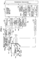
- FIG. 1 is a functional block diagram of an information processing system according to one embodiment of the invention.
- a display section consists of a combination of a desk 101 and a partition 102. The user sits on a chair in order to operate the information processing system. The user can use a pen 104, a keyboard 105, and a mouse 106 to input or handle information.
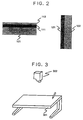
- a flat display 111 is disposed on the top of the desk 101 with almost all the area of the desk 101 being used as a display area and a transparent tablet 112 is mounted on the surface of the flat display 111.
- the transparent tablet 112 reads coordinates of the pen 104 ( Figure 1).
- a flat display 121 is embedded in the surface of the upright partition 102.
- a large screen CRT can also be used in place of the flat display 121.
- a projection display may also be used for projection on the desk, as shown in Figure 3.
- An output of the information processing system is displayed on a desk 301 by a video projector,in which case the desk 301 contains a tablet for inputting pen coordinates, but not a display.
- the desk 301 contains a tablet for inputting pen coordinates, but not a display.
- an image is projected from above the desk in Figure 3, it may be projected from the rear of the desk 301 with the surface of the desk 301 as a screen (described below in conjunction with Figure 4).
- the display section 101 will be hereinafter referred to as the flat display section and the display section 102 as the upright display section.
- a camera 107 is located above the flat display section 101 for monitoring the conditions on the desk.
- a picture from the camera 107 is input to an image processing section 151, which detects the positions of articles placed on the desk from the picture of the desk top and performs recognition processing 1000 of a hand motion of the user.
- the recognition result is sent to a desk top monitor section 153.
- the hand motion recognition process 1000 and an object handling process 1100 of a processing procedure execution section 157 are executed in direct conjunction with each other (described below).
- the desk top monitor section 153 reports information to an input processing section 155.
- the desk top monitor section 153 when detecting the user giving some instruction to the information processing system with his or her finger, the desk top monitor section 153 sends information concerning it to the input processing section 155. Also, the desk top monitor section 153 always stores the positions of the articles placed on the desk and can respond to an inquiry from any other functional block with information reporting the conditions on the desk.
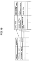
- the information stored in the desk top monitor section 153 is as a table as shown in Figure 10, for example.
- the entries under the left column of the table 1531 denote the meanings of information stored and how the conditions (or values) of the information are stored is indicated under the right column.
- included as the information are "condition of right hand of user,” “condition of left hand of user,” “coordinates of right hand of user,” “coordinates of left hand of user,” “coordinates of pen 104,” “coordinates of keyboard 105,” “coordinates of mouse 106,” “does user use pen?,” “does user use keyboard?,” “number of obstacles on desk,” and “area occupied by obstacles on desk.”
- the conditions of user's hands are classified into three categories, such as not on desk (N), pointing to something (P), and otherwise (C), for storage.
- the coordinates are stored as two integers indicating the coordinates of a display system on the display section 101.
- the information as to whether or not the user uses the pen (keyboard) is stored as the condition YES or NO.
- the number of obstacles on the desk is stored as an integer value indicating the count.
- the area occupied by obstacles on the desk is stored as a set of rectangular areas containing the obstacles.
- a camera 108 is located above the upright display section 102 for monitoring the conditions of the user.
- a picture from the camera 108 is input to an image processing section 152, which detects the position and direction of the user from the picture of the user and sends the result to a user monitor section 154.
- the user monitor section 154 always stores the conditions of the user and can respond to an inquiry from any other functional block with information reporting the conditions of the user.
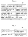
- Figure 11 shows a table of information stored in the user monitor section 154.
- the table 1541 like the table 1531 in Figure 10, stores information entries under the left column and the conditions under the right column.
- stored as the information are "is user present?,” "position of user's head,” and "direction of user's face.”
- the information as to whether or not the user is present is stored as the condition YES or NO.
- the position of the user's head is stored as a percentage of the position at which the head is placed in from left with respect to the desk width.
- the direction of the user's face is stored as the number of degrees the face inclines to right when viewed from the front.
- the input processing section 155 receives inputs of the user, namely, signals from the keyboard 105, the mouse 106, and the tablet 112, and inputs from the desk top monitor section 153, and determines the processing procedure to be executed in response to the inputs.
- information on the objects displayed on the screen such as a document image, icon, table, or graph, is considered in addition to the type of input from the user and the position information.
- the information is stored in a display content storage section 161.
- the display content storage section 161 can return information on the object displayed in the specified area. To provide information to find an empty area of display, the display content storage section 161 stores the screen area occupied by the displayed object as a set of rectangular areas.
- the processing procedure to be selected by the input processing section 155 in response to an input can be determined by the type of input and the attribute of the object displayed at the position where the input occurs. For example, assume that the user specifies one position on the display 111 with the pen 104. It is detected by the tablet 112 and reported to the input processing section 155, which then inquires of the display content storage section 161 what is displayed at the user-specified position on the display 111, and determines the processing procedure to be started based on the inquiry result and the fact that the user makes a specification with the pen 104. For example, if a page image of a document is displayed at the user-specified position, a processing procedure for editing the document is selected.
- the input processing section 155 references input processing definition data 156 to determine the processing procedure to be started from the attribute of object and the type of input.
- the input processing definition data 156 contains a table listing correspondence between the input types and the processing procedures to be started concerning all the types of objects that can be handled by the information processing system. That is, the processing procedure to be executed based on the type of input instruction is defined for each object, as shown in Figure 16. In the example in Figure 16, if the user depresses a mouse button, such as with a double click for the object of a document icon, a wordprocessor is accordingly started. If the user depresses and moves the pen for the document icon, the icon is moved accordingly.
- the hand motion of the operator is recognized by the recognition section 1000 and the object handling process 1100 (described below) is executed. If the operator inputs coordinates through the tablet 112 for the document image, character and graphics recognition 1200 is executed and document processing 1300 is performed or the gesture is recognized and edit processing 1500 is performed.
- the input processing section 155 informs the processing procedure execution section 157 of the determined processing procedure.
- the processing procedure execution section 157 reads the processing procedure specified by the input processing section 155 from the processing procedures 158 for execution.
- the processing procedure execution section 157 performs some predetermined processing according to the contents of the processing procedure being executed. In the description to follow, it is assumed that it becomes necessary to present some object to the user during the processing.
- the processing procedure execution section 157 which understands the contents of the object to be presented to the user, can calculate the object display size required when the object is displayed.
- the processing procedure execution section 157 transfers the size information of the object display area to a display position determination section 159 to determine the display position.
- the display position determination section 159 requests necessary information from the desk top monitor section 153, the user monitor section 154, and the display content storage section 161, and determines the display position in response to the returned information. That is, a visible and easy-to-operate position in front of the user (when the object is displayed on the flat display 111, a location with no obstacles on the desk and with an empty area for displaying the object) is an ideal display position. If the desk top monitor section 153 reports that the user intends to use the keyboard 105, the object needs to be displayed on the upright display 121 rather than the flat display 111 to facilitate keyboard entry.
- the desk top monitor section 153 reports that the user intends to use the pen 104, the object is displayed on the flat display 111 rather than the upright display 121 for convenient pen input. However, all conditions are not necessarily satisfied at the same time. Therefore, information to determine what condition takes precedence over other conditions is required.
- the priorities are provided as automatic allocation definition data 160. A specific example of the automatic allocation definition data 160 is given below.
- the display position determination section 159 returns the determined display position to the processing procedure execution section 157, which then issues a drawing command for displaying the object to a display control section 162 according to the display position.
- the display control section 162 draws the object on the flat display 111 or the upright display 121.
- the processing procedure execution section 157 reports the displayed object to the display content storage section 161, which then updates the stored information in response to the report.
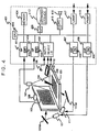
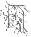
- FIG. 4 shows a hardware block diagram of the entire information processing system.
- a central information processor 401 comprises an input device interface 402, a CPU 403, a memory 404, display memories (DMs) 405 and 406, display interfaces (DI/Fs) 407 and 408, a secondary storage interface (SI/F) 409, a secondary storage 410, image processors (GPs) 411 and 413, image memories (GMs) 412 and 414, a sound interface 415, a loudspeaker 416, external communication interfaces LANI/F 417 and FAXI/F 418, etc.
- the image processor 411 is connected to the camera 107 and the image processor 413 to the camera 108.
- the displays of the display sections 101 and 102 are formed with the desk surface as a screen on which images are projected via mirrors 111M and 112M by projection displays 111 and 121 from the rear of the desk.
- the structures shown in Figures 2 and 3 may be used.
- the desk top monitor section 153, the user monitor section 154, the input processing section 155, the processing procedure execution section 157, the display position determination section 159, the display content storage section 161, and a part of the display control section 162 are all provided as programs stored in the memory 404, which are executed by the CPU 403.
- the input processing definition data 156, the processing procedures 158, and the automatic allocation definition data 160 are stored in the memory 404 or the secondary storage 410, and referenced or updated by the programs.
- the central information processor 401 reads signals via the input device interface 402 from the input devices, namely, the tablet 112, the keyboard 105, and the mouse 106.
- the CPU 403 processes inputs from the input devices in response to the program contents stored in the memory 404 and as a result, references or changes the contents of the memory 404 or the contents of the display memories 405 and 406 or references or updates the data stored in the secondary storage 410 via the secondary storage interface 409.
- the contents of the display memory 405 are output through the display interface 407 to the display 111.
- the contents of the display memory 406 are output through the display interface 408 to the display 121.
- the image processing section 151 described in conjunction with Figure 1 is provided by the image processor 411.
- the desk top state photographed by the camera 107 is input to the image processor 411 and is stored in the image memory 412.
- the display contents of the display 111 are preferably excluded from the image photographed by the camera 107, because a process of distinguishing the display contents from the articles on the desk top is otherwise required.
- the display contents of the display 111 can be excluded by temporarily clearing the display contents conforming to the timing at which the camera picks up an image. Since the image picking-up time is extremely short compared with the processing time of the taken-in image, the user does not feel a sense of incongruity even if the display during the picked-up image disappears. Since the timing at which the camera 107 picks up an image is controlled by the image processor 411, the process can be executed by the image processor 411 and the display interface 407 in synchronization with each other.
- the image processor 411 detects a hand motion of the user, for example, as described in REAL-TIME DETECTION OF POINTING ACTION FOR A GROVE-FREE INTERFACE, M.FUKUMOTO ET.AL, MVA'92 IAPR Workshop on Machine Vision Applications, 1992, and recognizes the attributes and motion of articles on the desk top, for example, as described in Visual Pattern Recognition Technologies, pp117-128, Trikeppus Corporation, 1983.
- the image processing section 152 described in conjunction with Figure 1 is provided by the image processor 413.
- the user state photographed by the camera 108 is input to the image processor 413 and is stored in the image memory 414.
- the image processor 413 recognizes the position, body direction, and motion of the user, for example, as described in Up-to-date Trend of Image Processing Algorithm, pp128-144, New Technical Communications Corporation, 1986. It can also estimate the position of the user by detecting a motion of the user's head as described in Head Reader: Real-time detection of Head Motion according to Image, DENSI JOHO TUSHIN GAKKAI RONBUNSI, D-II Vol.J74-D-II No.3 pp.398-406, 1991.
- Figure 12 shows the state around the desk in an environment in which the information processing system according to the embodiment is used. For convenience, the user is not shown in the figure.
- a window A01 showing a graph, a window A02 showing a tree structure of file organization, and a clock A03 are displayed on the upright display 121.
- a document page image A04 is displayed on the flat display 111.
- the flat display 111 Placed on the desk 101, namely, the flat display 111 are a vase A11, a notebook A12, the pen 104, the keyboard 105, and the mouse 106 as actual objects.
- the display also serves as a work space on the desk, which is an article of furniture. It must also be considered that various items as mentioned above are placed thereon.
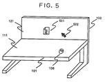
- Figure 5 shows an example of operation for the user to open an electronic document stored in the secondary storage 410.
- the document is displayed on the upright display 121, for example, as an icon 501.
- the user uses the mouse 106 placed on the desk 101 to move a pointer 502 displayed on the upright display 121 or the flat display 111 and that when the pointer 502 overlaps with the icon 501, the user can depress the button of the mouse 106 two successive times (double click) for converting the document into a page image to view the document contents.
- the pointer 502 is common to the flat and upright displays 111 and 121 and can move in response to a motion of the mouse without considering their boundaries.
- the input processing section 155 which can discern that the user has handled the button of the mouse 106 and discern the position of pointer 502 at the time, inquires of the display content storage section 161 what is displayed at the position of the pointer 502.
- the display content storage section 161 answers that the icon indicating a document file exists at the position.
- the input processing section 155 references the input processing definition data 156, selects a processing procedure to open the document, and reports it to the processing procedure execution section 157, which then fetches the specified processing procedure from the processing procedures 158 and starts execution of the processing procedure.
- the document is displayed according to the contents of the selected processing procedure by the processing procedure execution section 157.
- the processing procedure execution section 157 uses the function of the display position determination section 159 to obtain the display position of the document. How the display position determination section 159 determines the display position is described below.
- the display position determination section 159 determines to which of the flat display 111 and the upright display 121 the object is to be output. To do this, information as to whether or not the user uses the keyboard 105 can be used, for example. The information is stored in the desk top monitor section 153 as the table 1531 ( Figure 10), as described above. The display position determination section 159 inquires of the desk top monitor section 153 whether or not the user use the keyboard 105. If the user uses the keyboard 105, the display position determination section 159 decides that display of the object should be output to the upright display 121; otherwise, it decides that display of the object should be output to the flat display 111.
- the display position determination section 159 determines where the object is to be displayed in the display area of the display. A process flow for determining the display position is described below by taking display of the object on flat display 111 as an example.
- the conditions and the penalty values imposed when the conditions are not satisfied are related to each other in a table 1601 of the automatic allocation definition data 160 shown in Figure 13.
- the penalty value imposed when "A. fit to user position" is not satisfied is defined as 5, that when "B. avoid obstacles on desk” cannot be satisfied is defined as 10, and that when "C. prevent display overlapping" cannot be satisfied is defined as 3.
- the conditions and their corresponding penalty values are not limited to the example.
- the penalty values may be previously fixed, but preferably can be changed by the system or user.
- Figure 14 shows total penalty values imposed when only the condition A, B, or C or any combination thereof is satisfied. For example, when only conditions “A. fit to user position” and “B. avoid obstacles on desk” are satisfied, that is, when the condition “prevent display overlapping” is not satisfied (not decided), the penalty becomes 3 in total as seen from Figure 13. Likewise, when only the condition "B. avoid obstacles on desk” is satisfied, that is, when conditions “A. fit to user position" and “C. prevent display overlapping" are not decided, the penalty becomes 8 in total.
- the display position determination section 159 attempts to determine the display position starting at the combination corresponding to the smallest total penalty. That is, first the display position determination section 159 checks to see if the display position satisfying all conditions A, B, and C exists; if it exists, employs the display position; otherwise, checks to see if the display position satisfying conditions A and B exists; if it exists, employs the display position; otherwise, checks to see if the display position satisfying conditions B and C exists, and so forth on.
- the display position determination section 159 When the display position determination section 159 is given a combination of conditions to be attempted, it first finds regions that cannot be used to display the object from the given conditions, then checks to see if an area sufficient to display the object can be reserved so as not to overlap with any of the regions. If the area can be reserved, the display position determination section 159 uses the area as the display position of the object; otherwise, determines that the display position satisfying the given condition combination does not exist.
- the regions that cannot be used to display the object depending on the conditions are found as follows: First, an example in which the condition is "A. fit to user position" is described.
- the user position is discern by inquiring of the user monitor section 154. For example, when the user monitor section 154 reports that the user's head is positioned at the 30% position from the left end of the desk, the regions that cannot be used to display the object are found as the hatched portions in Figure 15. That is, if the region satisfying the condition A is defined as the region 1.5 times as wide as the object display, for example, with the user head as the center, other regions cannot be used for display of the object.
- the regions that cannot be used to display the object depending on the condition are discern by inquiring of the desk top monitor section 153. Since the desk top monitor section 153 holds the regions occupied by the obstacles on the desk as a set of rectangular regions, the set of the rectangular regions consists of regions that cannot be used for display of the object.
- the region that cannot be used to display objects depending on the condition are discern by inquiring of the display content storage section 161. Since the display content storage section 161 stores the regions occupied by the displayed objects as a set of rectangular regions, the set of the rectangular regions consists of regions that cannot be used for new object display.
- the display position can also be determined by a similar method.
- the process for avoiding obstacles can be omitted because no obstacles would be placed on the display 121 which is upright.
- the display screen of the integral input and display unit has almost the same size as the top of a desk, and unlike the case in which the user views a conventional CRT display from a slightly distant position, a position at which it is difficult to the user to view the display may occur depending on the sitting position or body direction of the user. Therefore, to present an object to the user, the sitting position and body direction of the user are preferably considered to determine the display position. For example, when the user sits on a chair to the left side of a desk as shown in Figure 6A, it is desired for the information processing system to present display at a position to the left on the flat display section 101, namely, the flat display 111 so that the user can easily see a document.
- the conditions of the user are photographed by the camera 108, and are recognized by the image processor 413, namely, the image processing section 152 as described above.
- the recognition result is stored in the table 1541 ( Figure 11) in the user monitor section 154. Therefore, desired operation is enabled by the fact that when determining the display position of a document, the display position determination section 159 requests the user position from the user monitor section 154 for presenting display at a proper position in response to the request result.
- the display 111 is integral with the desk 101 and may also be used as a normal work space on the desk. That is, the user may place the keyboard 105 and the mouse 106 on the desk for working and can place a notebook, dictionary, cup, etc., thereon.
- display position is determined avoiding places hidden by the articles on the desk. For example, assume that when a new document in the icon state is to be opened, the situation viewed from above the desk 101 is as shown in Figure 7A and that the flat display 111 displays the contents as shown in Figure 7B. At this time, if only the object on the desk are extracted, the result is as shown in Figure 7C.
- the picture as shown in Figure 7C is provided by temporarily clearing the display contents of the display 111 conforming to the timing at which the camera picks up an image as described above. From the picture, the image processor 411, namely, the image processing section 151 can detect the area occupied by the object on the desk, and information thereon is stored in the desk top monitor section 153.
- the display position determination section 159 requests the obstacle positions from the desk top monitor section 153 for presenting display at a proper position in response to the request result.
- the page image of a new document may be opened at a place where the obstacle is avoided, as shown in Figure 7D.
- the information processing system in the embodiment has a plurality of displays, it is necessary, in fact, to determine on which of the flat display 111 and the upright display 121 a picture is to be displayed. Since the camera 107 is located as means for monitoring the state of the desk top in the embodiment, the image processing result of this picture can be used to determine on which display an object is to be displayed.
- the information processing system displays the page image of a document
- image processing of a picture from the camera 107 indicates detection of obstacles on the desk and as a result
- the relation between the user hands and the keyboard is as shown in Figure 8A
- the center-of-gravity positions of the hand pictures, 802 and 803, and the center-of-gravity position of the keyboard picture, 804, obtained as a result of the image processing are used for specific determination.
- the keyboard center-of-gravity position 804 enters a polygon 801 indicated by the shaded portion in Figure 8B for example, it is determined that the user uses the keyboard for working.
- the polygon 801 is an area surrounded by the side of the desk 101 toward the user, the line passing through the center of gravity of the picture of the left hand of the user, 802, and perpendicular to the side of the desk 101 toward the user, the line passing through the center of gravity of the picture of the right hand of the user, 803, and perpendicular to the side of the desk 101 toward the user, and the line 30 cm forward from the line connecting the center of gravity of the picture of the left hand of the user, 802, and the center of gravity of the picture of the right hand of the user, 803, for example.
- the center-of-gravity position of the keyboard picture, 804 exists within the area of the polygon 801, thus it can be determined that the user attempts to use the keyboard for working.
- the user attempting to use the keyboard 105 can be detected by the method as described above and information thereon is stored in the desk top monitor section 153.
- the information is used by the display position determination section 159 and as a result, the information processing system can judge that the page image of the document may be displayed on the upright display 121 to facilitate keyboard entry of the user.
- the information processing system displays the page image of a document
- a picture from the camera 107 is processed by the image processing section 151 and obstacles on the desk are detected and as a result, the user picking up the pen 104 is detected as shown in Figure 9A
- the user attempts to use pen input for handling the document For example, the center-of-gravity position of the hand picture, 902, and the center-of-gravity position of the pen picture, 903, obtained as a result of the image processing are used for specific determination.
- the center-of-gravity position 903 of the pen 104 enters a circle 901 indicated by the shaded portion in Figure 9B for example, it is determined that the user uses the pen 104 for working.
- the distance from the center-of ⁇ the center-of-gravity position 902 of the picture of hand that the pen 104 is taken in is, for example, 8 cm or less.
- the center of gravity 903 of the picture of the pen 104 exists within the circle 901, thus it can be determined that the user attempts to use the pen 104 for working.
- the user attempting to use the pen 104 can be detected by the method as described above and information thereon is stored in the desk top monitor section 153.
- the information is used by the display position determination section 159 and as a result, the information processing system can judge that the page image of the document may be displayed on the flat display 111 to facilitate pen input of the user.
- the conditions of the user may also be estimated by using means for detecting the relative position between the desk 101 or partition 102 and the chair 103.
- information processing system provided with means for inputting the position of the user head or hand, information therefrom may also be used to estimate the conditions of the user.
- Such position input means is provided by attaching a small-sized magnetic field generator to the position measurement target and fixing a receiver to a desk or the like for measuring a magnetic field generated from the magnetic field generator for estimating the three-dimensional position and direction of the measurement target from a magnetic field change.
- a method of using an ultrasonic wave instead of the magnetic field is also proposed.
- the method of performing image processing of pictures from the camera photographing the desk top is used as means for detecting the user picking up the pen.
- similar operation can be performed if a function of detecting hand and pen coordinates with a technique other than image processing is provided.
- the method of reading a magnetic field or ultrasonic wave change described above can be used.
- the method of performing image processing of pictures from the camera photographing the desk top is used as means for detecting that the keyboard is placed in front of the user.
- similar operation can be performed if a function of detecting the coordinates of the user's hand or body and the keyboard with a technique other than image processing is provided.
- the method of reading a magnetic field or ultrasonic wave change described above can be used.
- hand motion and display object processing are previously related to each other as follows:
- Such relating and processing performed by the CPU 403 described above provides a more advanced integrated man-machine interface using hands and a tablet (pen).
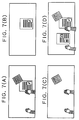
- Figures 17A to 17C are illustrations of move/rotation operations of a display object.
- Figure 17A represents a state in which a display object 130 is held by a hand 140-1 of a user.
- the user's other hand 140-2 is distant from the display object. In such a condition, display processing or file processing of the display object can be performed.
- the hand 140-1 is moved, such as shown in Figs 17 B and 17 C, the display object is moved following the motion of the hand.
- the user can rotate the display object 130 just like any natural object.
- Figs 18 A to C demonstrate file processing of a display object 130.
- two file icons 131, 132 are provided corresponding to the secondary storage 410 such as auxiliary memory and file input/output devices such as the FAX I/F 418 and the LAN I/F 417.
- the file A corresponds to the secondary storage 410 or a directory located on the secondary storage 410.
- the object 130 is also moved (130' ⁇ 130) according to the above-mentioned relating.
- the display object 130 overlaps the file A, the display brightness of the file A changes and an acceptance action of file operation is displayed.
- the processor 401 stores the document data corresponding to the display object 130 as a file in the secondary storage 401 or directory corresponding to the file A, and erases the display of the display object 130. After this, the stored document data file is displayed as one page of the file A.
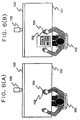
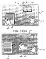
- Figures 19A and 19B are illustrations of a FAX transfer operation of a display object.
- the motion in Figure 19A is also judged to be a one ⁇ assume that a FAX transfer file previously exists on the flat display section 101 and that its destination is opened.
- the FAX transfer file 133 the name and telephone number of an associated party that can be selected as a destination is stored for each page, and the destination can be selected by opening its corresponding page.
- a corporation, Mr. Johnson is the FAX destination.
- the display brightness of the FAX transfer file 133 changes, informing the operator that the system is ready to accept a start command.
- the display object 130 is released, the destination telephone number is automatically dialed for transmitting the document file data corresponding to the display object 130.
- Figures 20A to 20D show a page turn operation.
- the turn place and turn amount or area are specified in response to the directions of the middle finger of the left hand, D1-D4, and hollow point coordinates between the thumb and forefinger of the left hand, P1-P4. Since the directions D1 and D2 are each upward left in Figures 20A and 20B, the turn place becomes an upper right portion. Moreover, as the hollow point coordinates approach the bottom, the turn area becomes larger. On the other hand, the directions D3 and D4 are each upward right in Figures 20C and 20D, and the turn place becomes a lower right portion. Thus, the turn place and turn amount or area can be changed as desired in response to the direction D and the hollow point coordinates P.
- the page turn direction (forward or backward) is judged according to a wave of the thumb.
- the subsequent thumb wave is assumed to be a forward direction.
- the subsequent thumb wave is assumed to be a backward direction.
- the subsequent wave changes to the forward direction; if the fingers are put together, the subsequent wave changes to the backward direction.
- the turn speed is proportional to the wave speed of the thumb.
- the page turn operation is performed by the left hand in the example in Figures 20A-20D, but may be performed by the right hand. Which hand the page turn operation is performed by is judged according to how much the object holding hand rests on the object.
- the page turn place and turn amount or area may be determined according to the place (four corners) when the operator holds the display object with both hands.
- the page turn direction may be defined as the forward direction when the operator waves the thumb of the left hand and the backward direction when the operator waves the thumb of the right hand.
- the page turn is reset when the operator releases his or her hold on the display object. That is, the pages are restored to the page unturned state.
- Figures 21A and 21B show page-out/page-in operation.
- the page-out/page-in operation is performed when the target page is found while pages are being turned. If the operator moves the one hand which is not used for the page turn operation so as to draw out the found page from the turn place as shown in Figure 21B while turning the pages as shown in Figure 21A, only this page is taken out for display (page-out). In contrast, if the operator returns the hand, the page is displayed at the former position (page-in).
- Figures 22A and 22B illustrate a page loosening operation.
- the page loosening operation means that if the operator moves one of the hands holding the display object when pages are not turned, pages are loosened for display accordingly, as shown in Figures 22A and 22B.
- the distance between pages is determined by the move distance. That is, if the move distance is short, the pages greatly overlap each other; if the move distance is long, the pages overlap each other less and are loosened.
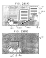
- Figures 23A and 23B show a page gathering operation, which gathers loose pages.
- Page replacement can be accomplished by temporarily taking out the target page using the page-out/page-in operation when pages are turned, turning to the insertion page, and inserting the target page in the place by page-out/page ⁇ pages and then accepting a move operation as described above for changing the arrangement or order of the pages.
- Figure 24A shows a situation in which after moving a display object (130' ⁇ 130), the operator enters characters in the display object 130 with the pen 104.
- the entered character string of up to "Character enterin” has been recognized and is displayed.
- entering the character "g” has not yet been completed, thus the character has not yet been recognized and the incomplete form of the character part is displayed.
- character recognition is started and the character corresponding to the recognition result is displayed in place of the display of the incomplete character part.
- the code of the character corresponding to the recognition result is described at the corresponding position in the document data file in the memory 402.
- the entry end of each character is recognized by character cutout processing such as frame cutout or timeout cutout.
- a mode change menu may be displayed for the operator to specify a mode change with the pen or the mode may be changed in response to the relationship between the object to be edited and pen input stroke length or a dedicated switch to mode change may be located on the pen.
- graphics can also be entered and edited in a similar manner.
- the transition is made to the page handling processing mode; however, when the user holds the pen 104 in his hand, the transition to the mode is preferably inhibited in order to enable the user to perform pen input operation with both hands as shown in Figures 24A and 24B.
- Such control is provided by monitoring hand motion of the user by a monitor camera for detecting the user holding the pen and inhibiting the transition to the page handling processing mode in response to the detection.
- hand motion is recognized from an image read into the memory 404 and operation commands and parameters are found in response to the recognition.
- Figure 25 shows the processing sequence of the hand motion recognition process 1000.
- the difference image found at step 1005 is filtered to remove noise at step 1010.
- the filtering can be performed using a spatial filter widely used for the purpose.
- the hand form is extracted at step 1015, thereby removing other objects than the hand on the flat display section 101.
- the hand form is extracted and others are removed.
- the hand position and hand move direction, gradient, etc. can be sensed from the found hand form.
- the hand form can be recognized by using techniques described in Non-contact Hand Form Recognition and Its Application by Izumi OKAMURA and Akira SUMIMOTO, "SHINGAKU GIHOU” HC93-6 (1993-05), DENKI JOUHOU TUSHIN GAKKAI, for example.
- the hand form size substantially equals the previously learned hand size is determined. If they are substantially equal, whether or not the hand position (on the flat display section 101) overlaps the display object is determined at step 1020. If the hand form size differs from the previously learned hand size or if the hand position does not overlap the display object, it is judged that the display object is released, and OBJECT RELEASE mode is set at step 1055. On the other hand, if the hand form size substantially equals the previously learned hand size and the hand position overlaps the display object, it is judged that the display object is held, and OBJECT HOLD mode is set at step 1025.
- LAYOUT/FILE mode is set at step 1035. If the display object is held with both hands, PAGE HANDLING mode is set at step 1045.
- LAYOUT/FILE mode when the LAYOUT/FILE mode is set, a change in the hand form is traced, and parameters of the object holding hand are calculated at step 1040.
- the coordinates after a move of the hand form and the gradient of the wrist, etc., are used as the parameters.
- the wrist gradient can be judged from the middle finger direction D shown in Figures 20A-20D.
- the PAGE HANDLING mode When the PAGE HANDLING mode is set, a change in the hand form is traced, and parameters of both hands holding the object are calculated at step 1050. In addition to the parameters for one hand, the wave state of the thumb is detected. It can be found from a change in the relative position of the thumb tip to the palm.
- the object handling process 1100 Upon completion of setting the mode and calculating the parameters, the object handling process 1100 is performed.
- the object handling process 1100 is described below.
- Figure 26 shows the processing sequence of the object handling process 1100.
- the mode set in the hand motion recognition process 1000 is judged LAYOUT/FILE, PAGE HANDLING, or RELEASE at step 1105.
- move display and rotation display of the held display object are performed based on the move destination coordinates and gradient data of the hand form, as shown in Figures 17A ⁇ characters, graphics, etc., are rotated for display as if the paper were tilted.
- a friction sound such as would be generated between a desk and paper may be artificially produced and output via the sound interface 415 from the loudspeaker 416, thereby raising the feeling of reality.
- the file processing varies depending on whether the display that the display object overlaps represents the secondary storage 410 or an external communication device such as a facsimile machine. If it represents a directory on the secondary storage as shown in Figures 18A and 18B, the document data file corresponding to the display object is stored in the secondary storage 410 or the corresponding directory. If FAX is represented as shown in Figures 19A and 19B, the document data file corresponding to the display object is transmitted via the FAX I/F 418. If LAN is represented, the document data file is transmitted via the LAN I/F 417.
- step 1105 first whether or not a page turn operation is being performed is determined by checking to see if the operator waves his or her thumb at step 1125. If the page turn operation is being performed, page turn/page-out/page-in processing shown in Figures 20A to 20D, 21A and 21B is performed at step 1130.
- page loosening/page gathering processing shown in Figures 22A and 22B, 23A and 23B is performed at step 1135. At this time, page loosening or gathering is performed in response to the relationship between a change in the coordinates of one moving hand and the coordinates of the other fixed hand.
- page turn sound may be artificially produced and output via the sound interface 415 from the loudspeaker 416, as with the layout processing.
- release processing is performed at step 1140.
- the release processing is performed when the operator releases his or her hold on the display object. For example, when release is executed during layout processing or when one hand is released during page handling for pen input, release processing is performed.
- the mode set in the hand motion recognition process 1000 is cleared and a wait is made until a new mode is set and parameters are calculated in the hand motion recognition process 1000.
- a pressure sensor may be attached to the panel face of the flat display for determining whether the operator takes or releases his or her hold in response to the sensing result of the sensor.
- the pressure sensor senses the operator placing his or her palm on the flat display. If the operator does not place his or her palm on the flat display, it is always judged that the release state is entered.
- the pressure sensor is capable of sensing a plurality of points at the same time.
- the palm on the horizontal face on the flat display may be sensed by a camera or an optical sensor for determining whether the operator takes or releases his or her hold of the display object.
- a printer server, file server, etc., connected to LAN may be made available by a similar technique.
- icons representing the devices are displayed on the flat display so that the user can use them.
- Hand motion is monitored by the overhead camera in the embodiment.
- a camera may be located below the flat display (rear side), thereby monitoring a hand shadow picture for monitoring hand motion. This makes it possible to relieve psychological pressure exerted upon the user as a result of overhead camera monitoring.
- the flat display is installed horizontally like a normal desk in the description, the display may be installed uprightly so that it can be used like a blackboard. This arrangement is useful for presentation, etc.
- the display object displayed on the flat display and the operator hands are monitored by the overhead camera for recognizing hand motion and the display object can be handled in response to the recognition. Therefore, it can provide a man-machine interface which enables the user to manipulate document data as if he or she handled actual paper.
- the upright front display is provided in addition to the flat display installed horizontally,abstract pictures such as an organization chart and an office layout diagram and a notice board such as a schedule table and a list of business showings can be displayed on the front display for improving office work efficiency.
- the pen input environment enables the user to easily enter characters and graphics as required.
- the user can also use gesture commands with the pen for easy editing.
Applications Claiming Priority (6)
| Application Number | Priority Date | Filing Date | Title |
|---|---|---|---|
| JP05609993A JP3378604B2 (ja) | 1993-03-16 | 1993-03-16 | 情報処理装置 |
| JP5609993 | 1993-03-16 | ||
| JP56099/93 | 1993-03-16 | ||
| JP225949/93 | 1993-09-10 | ||
| JP22594993 | 1993-09-10 | ||
| JP22594993A JPH0784715A (ja) | 1993-09-10 | 1993-09-10 | 情報処理装置 |
Publications (3)
| Publication Number | Publication Date |
|---|---|
| EP0626636A2 true EP0626636A2 (fr) | 1994-11-30 |
| EP0626636A3 EP0626636A3 (fr) | 1996-10-02 |
| EP0626636B1 EP0626636B1 (fr) | 2001-09-12 |
Family
ID=26397027
Family Applications (1)
| Application Number | Title | Priority Date | Filing Date |
|---|---|---|---|
| EP94104123A Expired - Lifetime EP0626636B1 (fr) | 1993-03-16 | 1994-03-16 | Interface utilisateur pour un système de traitement d'information |
Country Status (3)
| Country | Link |
|---|---|
| US (1) | US5436639A (fr) |
| EP (1) | EP0626636B1 (fr) |
| DE (1) | DE69428229T2 (fr) |
Cited By (33)
| Publication number | Priority date | Publication date | Assignee | Title |
|---|---|---|---|---|
| EP0715248A1 (fr) * | 1994-12-02 | 1996-06-05 | Hitachi, Ltd. | Dispositif d'entrée de coordonnées avec plusieurs affichages |
| EP0783149A1 (fr) * | 1995-10-14 | 1997-07-09 | Rank Xerox Limited | Presse-papier pour système de bureau interactif |
| WO1998038533A1 (fr) * | 1997-02-28 | 1998-09-03 | Siemens Aktiengesellschaft | Agencement et procede pour la detection d'un objet dans une zone irradiee par des ondes dans le domaine spectral invisible |
| US6005547A (en) * | 1995-10-14 | 1999-12-21 | Xerox Corporation | Calibration of an interactive desktop system |
| EP0982676A1 (fr) * | 1998-08-27 | 2000-03-01 | Hewlett-Packard Company | Procédé et dispositif pour une affichage/clavier pour un assistant numérique personnel |
| EP0987622A2 (fr) * | 1998-09-17 | 2000-03-22 | Xerox Corporation | Collage d'information monté sur une surface |
| WO2000021024A1 (fr) * | 1998-10-07 | 2000-04-13 | Intel Corporation | Dispositif de saisie utilisant des detecteurs de balayage |
| WO2000055802A1 (fr) * | 1999-03-17 | 2000-09-21 | Siemens Aktiengesellschaft | Installation pour interaction |
| WO2000075860A1 (fr) * | 1999-06-08 | 2000-12-14 | Soffix, S.R.L. | Dispositif d'ecriture/affichage electronique et technique d'exploitation |
| WO2003054683A2 (fr) * | 2001-12-07 | 2003-07-03 | Canesta Inc. | Interface lumineuse amelioree pour dispositifs electroniques |
| US6690357B1 (en) | 1998-10-07 | 2004-02-10 | Intel Corporation | Input device using scanning sensors |
| US6712952B1 (en) | 1998-06-05 | 2004-03-30 | Cambridge Univ. Technical Services, Ltd. | Removal of substances from metal and semi-metal compounds |
| US7259747B2 (en) | 2001-06-05 | 2007-08-21 | Reactrix Systems, Inc. | Interactive video display system |
| US7340077B2 (en) | 2002-02-15 | 2008-03-04 | Canesta, Inc. | Gesture recognition system using depth perceptive sensors |
| US7348963B2 (en) | 2002-05-28 | 2008-03-25 | Reactrix Systems, Inc. | Interactive video display system |
| WO2008085788A2 (fr) * | 2007-01-06 | 2008-07-17 | Apple Inc. | Détection et interprétation de gestes du monde réel et de gestes de sécurité sur des dispositifs tactiles et sensibles à l'effleurement |
| US7576727B2 (en) | 2002-12-13 | 2009-08-18 | Matthew Bell | Interactive directed light/sound system |
| US7710391B2 (en) | 2002-05-28 | 2010-05-04 | Matthew Bell | Processing an image utilizing a spatially varying pattern |
| US7809167B2 (en) | 2003-10-24 | 2010-10-05 | Matthew Bell | Method and system for processing captured image information in an interactive video display system |
| US8035624B2 (en) | 2002-05-28 | 2011-10-11 | Intellectual Ventures Holding 67 Llc | Computer vision based touch screen |
| US8081822B1 (en) | 2005-05-31 | 2011-12-20 | Intellectual Ventures Holding 67 Llc | System and method for sensing a feature of an object in an interactive video display |
| US8159682B2 (en) | 2007-11-12 | 2012-04-17 | Intellectual Ventures Holding 67 Llc | Lens system |
| US8199108B2 (en) | 2002-12-13 | 2012-06-12 | Intellectual Ventures Holding 67 Llc | Interactive directed light/sound system |
| US8230367B2 (en) | 2007-09-14 | 2012-07-24 | Intellectual Ventures Holding 67 Llc | Gesture-based user interactions with status indicators for acceptable inputs in volumetric zones |
| US8259163B2 (en) | 2008-03-07 | 2012-09-04 | Intellectual Ventures Holding 67 Llc | Display with built in 3D sensing |
| CN101848252B (zh) * | 2009-03-24 | 2012-10-10 | 鸿富锦精密工业(深圳)有限公司 | 移动电话 |
| US8487866B2 (en) | 2003-10-24 | 2013-07-16 | Intellectual Ventures Holding 67 Llc | Method and system for managing an interactive video display system |
| US8595218B2 (en) | 2008-06-12 | 2013-11-26 | Intellectual Ventures Holding 67 Llc | Interactive display management systems and methods |
| WO2015030795A1 (fr) | 2013-08-30 | 2015-03-05 | Hewlett Packard Development Company, L.P. | Association d'entrée tactile |
| US9128519B1 (en) | 2005-04-15 | 2015-09-08 | Intellectual Ventures Holding 67 Llc | Method and system for state-based control of objects |
| US9165368B2 (en) | 2005-02-08 | 2015-10-20 | Microsoft Technology Licensing, Llc | Method and system to segment depth images and to detect shapes in three-dimensionally acquired data |
| CH710672A1 (de) * | 2015-02-18 | 2016-08-31 | Gök Metin | Verfahren und System zum lnformationsaustausch. |
| US10242255B2 (en) | 2002-02-15 | 2019-03-26 | Microsoft Technology Licensing, Llc | Gesture recognition system using depth perceptive sensors |
Families Citing this family (100)
| Publication number | Priority date | Publication date | Assignee | Title |
|---|---|---|---|---|
| EP0622722B1 (fr) * | 1993-04-30 | 2002-07-17 | Xerox Corporation | Système de copie interactive |
| US6061064A (en) | 1993-08-31 | 2000-05-09 | Sun Microsystems, Inc. | System and method for providing and using a computer user interface with a view space having discrete portions |
| US5732227A (en) * | 1994-07-05 | 1998-03-24 | Hitachi, Ltd. | Interactive information processing system responsive to user manipulation of physical objects and displayed images |
| US5490244A (en) * | 1994-03-24 | 1996-02-06 | International Business Machines Corporation | System and method for transmitting a computer object |
| JPH07271501A (ja) * | 1994-03-31 | 1995-10-20 | Wacom Co Ltd | 表示画面における表示物の表示方法 |
| US5528263A (en) * | 1994-06-15 | 1996-06-18 | Daniel M. Platzker | Interactive projected video image display system |
| US6266057B1 (en) * | 1995-07-05 | 2001-07-24 | Hitachi, Ltd. | Information processing system |
| US6335737B1 (en) * | 1994-10-21 | 2002-01-01 | International Business Machines Corporation | Video display and selection on a graphical interface |
| US6281878B1 (en) | 1994-11-01 | 2001-08-28 | Stephen V. R. Montellese | Apparatus and method for inputing data |
| US5903904A (en) * | 1995-04-28 | 1999-05-11 | Ricoh Company | Iconic paper for alphabetic, japanese and graphic documents |
| US5717940A (en) * | 1995-04-28 | 1998-02-10 | Ricoh Company, Ltd. | Method of selecting a target document using features of an example page |
| US5831601A (en) * | 1995-06-07 | 1998-11-03 | Nview Corporation | Stylus position sensing and digital camera with a digital micromirror device |
| US6044165A (en) * | 1995-06-15 | 2000-03-28 | California Institute Of Technology | Apparatus and method for tracking handwriting from visual input |
| DE19546749C1 (de) * | 1995-12-14 | 1997-07-24 | Friedemann Weber | Zeichentisch zur Darstellung und Bearbeitung von Computeranwendungen |
| US5784487A (en) * | 1996-05-23 | 1998-07-21 | Xerox Corporation | System for document layout analysis |
| US5903632A (en) * | 1997-03-19 | 1999-05-11 | Tmax Technologies Inc. | Automated telephone directory |
| US6252598B1 (en) * | 1997-07-03 | 2001-06-26 | Lucent Technologies Inc. | Video hand image computer interface |
| US6124848A (en) * | 1997-08-01 | 2000-09-26 | Lsi Logic Corporation | Method and apparatus for reducing flat panel display horizontal scan signal interference in the electrostatic pen operated digitizer |
| DE19739285C1 (de) * | 1997-09-08 | 1998-11-19 | Siemens Nixdorf Inf Syst | Vorrichtung zur Darstellung und virtuellen Eingabe von Daten |
| US6175954B1 (en) * | 1997-10-30 | 2001-01-16 | Fuji Xerox Co., Ltd. | Computer programming using tangible user interface where physical icons (phicons) indicate: beginning and end of statements and program constructs; statements generated with re-programmable phicons and stored |
| WO1999038149A1 (fr) | 1998-01-26 | 1999-07-29 | Wayne Westerman | Procede et dispositif d'integration d'entree manuelle |
| US6043805A (en) * | 1998-03-24 | 2000-03-28 | Hsieh; Kuan-Hong | Controlling method for inputting messages to a computer |
| DE29805869U1 (de) * | 1998-03-31 | 1999-09-02 | Fitzner Kurt Dieter | Ein-/Ausgabegerät mit Display |
| US6377704B1 (en) | 1998-04-30 | 2002-04-23 | Xerox Corporation | Method for inset detection in document layout analysis |
| US6088018A (en) * | 1998-06-11 | 2000-07-11 | Intel Corporation | Method of using video reflection in providing input data to a computer system |
| US6677934B1 (en) * | 1999-07-30 | 2004-01-13 | L-3 Communications | Infrared touch panel with improved sunlight rejection |
| WO2001052230A1 (fr) * | 2000-01-10 | 2001-07-19 | Ic Tech, Inc. | Procede et systeme permettant d'interagir avec un dispositif d'affichage |
| JP2001209487A (ja) * | 2000-01-25 | 2001-08-03 | Uw:Kk | 筆跡通信システムおよび該システムで使用される筆跡入力装置及び筆跡表示装置 |
| JP3867512B2 (ja) * | 2000-06-29 | 2007-01-10 | 富士ゼロックス株式会社 | 画像処理装置および画像処理方法、並びにプログラム |
| WO2002019151A1 (fr) * | 2000-08-31 | 2002-03-07 | The Gadget Factory | Publication electronique |
| US6895520B1 (en) | 2001-03-02 | 2005-05-17 | Advanced Micro Devices, Inc. | Performance and power optimization via block oriented performance measurement and control |
| US7061468B2 (en) * | 2001-04-10 | 2006-06-13 | Logitech Europe S.A. | Hybrid presentation controller and computer input device |
| US8300042B2 (en) | 2001-06-05 | 2012-10-30 | Microsoft Corporation | Interactive video display system using strobed light |
| JP3920067B2 (ja) * | 2001-10-09 | 2007-05-30 | 株式会社イーアイティー | 座標入力装置 |
| JP4009850B2 (ja) * | 2002-05-20 | 2007-11-21 | セイコーエプソン株式会社 | 投写型画像表示システム、プロジェクタ、プログラム、情報記憶媒体および画像投写方法 |
| JP4009851B2 (ja) * | 2002-05-20 | 2007-11-21 | セイコーエプソン株式会社 | 投写型画像表示システム、プロジェクタ、プログラム、情報記憶媒体および画像投写方法 |
| JP4102105B2 (ja) * | 2002-05-24 | 2008-06-18 | 株式会社日立製作所 | 電子ペンを利用した書類記入システム |
| US6654001B1 (en) * | 2002-09-05 | 2003-11-25 | Kye Systems Corp. | Hand-movement-sensing input device |
| US7671843B2 (en) * | 2002-11-12 | 2010-03-02 | Steve Montellese | Virtual holographic input method and device |
| JP4220408B2 (ja) * | 2004-02-13 | 2009-02-04 | 株式会社日立製作所 | テーブル型情報端末 |
| WO2005091124A1 (fr) * | 2004-03-18 | 2005-09-29 | Koninklijke Philips Electronics N.V. | Appareil de balayage d'ecran |
| US20050227217A1 (en) * | 2004-03-31 | 2005-10-13 | Wilson Andrew D | Template matching on interactive surface |
| US7379562B2 (en) * | 2004-03-31 | 2008-05-27 | Microsoft Corporation | Determining connectedness and offset of 3D objects relative to an interactive surface |
| US7394459B2 (en) * | 2004-04-29 | 2008-07-01 | Microsoft Corporation | Interaction between objects and a virtual environment display |
| US20050273201A1 (en) * | 2004-06-06 | 2005-12-08 | Zukowski Deborra J | Method and system for deployment of sensors |
| US7787706B2 (en) * | 2004-06-14 | 2010-08-31 | Microsoft Corporation | Method for controlling an intensity of an infrared source used to detect objects adjacent to an interactive display surface |
| US7593593B2 (en) | 2004-06-16 | 2009-09-22 | Microsoft Corporation | Method and system for reducing effects of undesired signals in an infrared imaging system |
| US7519223B2 (en) * | 2004-06-28 | 2009-04-14 | Microsoft Corporation | Recognizing gestures and using gestures for interacting with software applications |
| US7719523B2 (en) | 2004-08-06 | 2010-05-18 | Touchtable, Inc. | Bounding box gesture recognition on a touch detecting interactive display |
| US7724242B2 (en) * | 2004-08-06 | 2010-05-25 | Touchtable, Inc. | Touch driven method and apparatus to integrate and display multiple image layers forming alternate depictions of same subject matter |
| US7728821B2 (en) | 2004-08-06 | 2010-06-01 | Touchtable, Inc. | Touch detecting interactive display |
| US20070046643A1 (en) * | 2004-08-06 | 2007-03-01 | Hillis W Daniel | State-Based Approach to Gesture Identification |
| US8560972B2 (en) * | 2004-08-10 | 2013-10-15 | Microsoft Corporation | Surface UI for gesture-based interaction |
| US7576725B2 (en) * | 2004-10-19 | 2009-08-18 | Microsoft Corporation | Using clear-coded, see-through objects to manipulate virtual objects |
| JP4689684B2 (ja) | 2005-01-21 | 2011-05-25 | ジェスチャー テック,インコーポレイテッド | 動作に基づくトラッキング |
| US7499027B2 (en) * | 2005-04-29 | 2009-03-03 | Microsoft Corporation | Using a light pointer for input on an interactive display surface |
| US7719519B2 (en) * | 2005-06-24 | 2010-05-18 | Hewlett-Packard Development Company, L.P. | Input device which emits and/or reflects optical electromagnetic radiation for use on a display screen |
| US7525538B2 (en) * | 2005-06-28 | 2009-04-28 | Microsoft Corporation | Using same optics to image, illuminate, and project |
| US7911444B2 (en) | 2005-08-31 | 2011-03-22 | Microsoft Corporation | Input method for surface of interactive display |
| US8098277B1 (en) | 2005-12-02 | 2012-01-17 | Intellectual Ventures Holding 67 Llc | Systems and methods for communication between a reactive video system and a mobile communication device |
| US8060840B2 (en) | 2005-12-29 | 2011-11-15 | Microsoft Corporation | Orientation free user interface |
| US7515143B2 (en) * | 2006-02-28 | 2009-04-07 | Microsoft Corporation | Uniform illumination of interactive display panel |
| US20080096651A1 (en) * | 2006-07-28 | 2008-04-24 | Aruze Corp. | Gaming machine |
| US8212857B2 (en) * | 2007-01-26 | 2012-07-03 | Microsoft Corporation | Alternating light sources to reduce specular reflection |
| JP5256561B2 (ja) * | 2007-06-04 | 2013-08-07 | 島根県 | 情報入力装置、情報出力装置および方法 |
| US8669938B2 (en) * | 2007-11-20 | 2014-03-11 | Naturalpoint, Inc. | Approach for offset motion-based control of a computer |
| US8228345B2 (en) * | 2008-09-24 | 2012-07-24 | International Business Machines Corporation | Hand image feedback method and system |
| JP2010157854A (ja) * | 2008-12-26 | 2010-07-15 | Sony Corp | 情報処理装置、情報処理方法およびプログラム |
| US8467133B2 (en) | 2010-02-28 | 2013-06-18 | Osterhout Group, Inc. | See-through display with an optical assembly including a wedge-shaped illumination system |
| AU2011220382A1 (en) | 2010-02-28 | 2012-10-18 | Microsoft Corporation | Local advertising content on an interactive head-mounted eyepiece |
| US8482859B2 (en) | 2010-02-28 | 2013-07-09 | Osterhout Group, Inc. | See-through near-eye display glasses wherein image light is transmitted to and reflected from an optically flat film |
| US9229227B2 (en) | 2010-02-28 | 2016-01-05 | Microsoft Technology Licensing, Llc | See-through near-eye display glasses with a light transmissive wedge shaped illumination system |
| US20150309316A1 (en) | 2011-04-06 | 2015-10-29 | Microsoft Technology Licensing, Llc | Ar glasses with predictive control of external device based on event input |
| US20120200601A1 (en) * | 2010-02-28 | 2012-08-09 | Osterhout Group, Inc. | Ar glasses with state triggered eye control interaction with advertising facility |
| US9134534B2 (en) | 2010-02-28 | 2015-09-15 | Microsoft Technology Licensing, Llc | See-through near-eye display glasses including a modular image source |
| US8472120B2 (en) | 2010-02-28 | 2013-06-25 | Osterhout Group, Inc. | See-through near-eye display glasses with a small scale image source |
| US9759917B2 (en) | 2010-02-28 | 2017-09-12 | Microsoft Technology Licensing, Llc | AR glasses with event and sensor triggered AR eyepiece interface to external devices |
| US9097890B2 (en) | 2010-02-28 | 2015-08-04 | Microsoft Technology Licensing, Llc | Grating in a light transmissive illumination system for see-through near-eye display glasses |
| US9091851B2 (en) | 2010-02-28 | 2015-07-28 | Microsoft Technology Licensing, Llc | Light control in head mounted displays |
| US9223134B2 (en) | 2010-02-28 | 2015-12-29 | Microsoft Technology Licensing, Llc | Optical imperfections in a light transmissive illumination system for see-through near-eye display glasses |
| US9128281B2 (en) | 2010-09-14 | 2015-09-08 | Microsoft Technology Licensing, Llc | Eyepiece with uniformly illuminated reflective display |
| US9285589B2 (en) | 2010-02-28 | 2016-03-15 | Microsoft Technology Licensing, Llc | AR glasses with event and sensor triggered control of AR eyepiece applications |
| US8488246B2 (en) | 2010-02-28 | 2013-07-16 | Osterhout Group, Inc. | See-through near-eye display glasses including a curved polarizing film in the image source, a partially reflective, partially transmitting optical element and an optically flat film |
| US9366862B2 (en) | 2010-02-28 | 2016-06-14 | Microsoft Technology Licensing, Llc | System and method for delivering content to a group of see-through near eye display eyepieces |
| US9182596B2 (en) | 2010-02-28 | 2015-11-10 | Microsoft Technology Licensing, Llc | See-through near-eye display glasses with the optical assembly including absorptive polarizers or anti-reflective coatings to reduce stray light |
| US9097891B2 (en) | 2010-02-28 | 2015-08-04 | Microsoft Technology Licensing, Llc | See-through near-eye display glasses including an auto-brightness control for the display brightness based on the brightness in the environment |
| US20120249797A1 (en) | 2010-02-28 | 2012-10-04 | Osterhout Group, Inc. | Head-worn adaptive display |
| US9129295B2 (en) | 2010-02-28 | 2015-09-08 | Microsoft Technology Licensing, Llc | See-through near-eye display glasses with a fast response photochromic film system for quick transition from dark to clear |
| US8477425B2 (en) | 2010-02-28 | 2013-07-02 | Osterhout Group, Inc. | See-through near-eye display glasses including a partially reflective, partially transmitting optical element |
| US9341843B2 (en) | 2010-02-28 | 2016-05-17 | Microsoft Technology Licensing, Llc | See-through near-eye display glasses with a small scale image source |
| US10180572B2 (en) | 2010-02-28 | 2019-01-15 | Microsoft Technology Licensing, Llc | AR glasses with event and user action control of external applications |
| JP5756704B2 (ja) | 2011-07-27 | 2015-07-29 | 京セラ株式会社 | 表示機器および制御プログラム |
| US20130120269A1 (en) * | 2011-10-11 | 2013-05-16 | Exopc | Desktop for a computer and method for providing same |
| US20130179811A1 (en) * | 2012-01-05 | 2013-07-11 | Visteon Global Technologies, Inc. | Projection dynamic icon knobs |
| US8995737B2 (en) * | 2012-01-20 | 2015-03-31 | Canon Kabushiki Kaisha | Image processing apparatus and image processing method |
| US9122527B2 (en) | 2012-08-21 | 2015-09-01 | International Business Machines Corporation | Resource allocation for migration within a multi-tiered system |
| US20140205138A1 (en) * | 2013-01-18 | 2014-07-24 | Microsoft Corporation | Detecting the location of a keyboard on a desktop |
| US20170039867A1 (en) | 2013-03-15 | 2017-02-09 | Study Social, Inc. | Mobile video presentation, digital compositing, and streaming techniques implemented via a computer network |
| JP6141108B2 (ja) * | 2013-06-07 | 2017-06-07 | キヤノン株式会社 | 情報処理装置およびその方法 |
| JP6058614B2 (ja) * | 2014-10-31 | 2017-01-11 | 京セラドキュメントソリューションズ株式会社 | 画像処理装置及び画像処理方法 |
Citations (4)
| Publication number | Priority date | Publication date | Assignee | Title |
|---|---|---|---|---|
| EP0055366A2 (fr) * | 1980-12-30 | 1982-07-07 | International Business Machines Corporation | Système d'affichage et de lecture d'information à distance utilisant le parallaxe d'ombres |
| EP0378889A1 (fr) * | 1989-01-19 | 1990-07-25 | Dean A. Corren | Interface utilisateur pour un système d'ordinateur |
| EP0495622A2 (fr) * | 1991-01-14 | 1992-07-22 | Xerox Corporation | Indexation d'ensembles de données |
| EP0622722A2 (fr) * | 1993-04-30 | 1994-11-02 | Rank Xerox Limited | Système de copie interactive |
Family Cites Families (2)
| Publication number | Priority date | Publication date | Assignee | Title |
|---|---|---|---|---|
| US4827410A (en) * | 1986-07-21 | 1989-05-02 | Corren Dean R | Computer system user interface |
| JPS63170780A (ja) * | 1986-10-03 | 1988-07-14 | インタランド・コーポレーション | 一体化したマルチ・ディスプレイ型のオーバーレイ制御式通信ワークステーション |
-
1994
- 1994-03-15 US US08/213,030 patent/US5436639A/en not_active Expired - Lifetime
- 1994-03-16 EP EP94104123A patent/EP0626636B1/fr not_active Expired - Lifetime
- 1994-03-16 DE DE69428229T patent/DE69428229T2/de not_active Expired - Fee Related
Patent Citations (4)
| Publication number | Priority date | Publication date | Assignee | Title |
|---|---|---|---|---|
| EP0055366A2 (fr) * | 1980-12-30 | 1982-07-07 | International Business Machines Corporation | Système d'affichage et de lecture d'information à distance utilisant le parallaxe d'ombres |
| EP0378889A1 (fr) * | 1989-01-19 | 1990-07-25 | Dean A. Corren | Interface utilisateur pour un système d'ordinateur |
| EP0495622A2 (fr) * | 1991-01-14 | 1992-07-22 | Xerox Corporation | Indexation d'ensembles de données |
| EP0622722A2 (fr) * | 1993-04-30 | 1994-11-02 | Rank Xerox Limited | Système de copie interactive |
Non-Patent Citations (3)
| Title |
|---|
| CHI '92 CONFERENCE PROCEEDINGS, STRIKING A BALANCE, MONTEREY, MAY 3 - 7, 1992, no. -, 3 May 1992, BAUERSFELD P;BENNETT J; LYNCH G, pages 627-634, XP000426843 MANDER R ET AL: "A 'PILE' METAPHOR FOR SUPPORTING CASUAL ORGANIZATION OF INFORMATION" * |
| MYRON W. KRUEGER: "ARTIFICIAL REALITY" 1983 , ADDISON-WESLEY PUBLISHING COMPANY , USA XP002009298 Chapter 10, page 140- page 149 * page 143, paragraph 3 - page 147, paragraph 3 * * |
| PROCEEDINGS OF THE SYMPOSIUM ON USER INTERFACE SOFTWARE AND TECHNOLOGY ( UIST ), HILTON HEAD, S. CAROLINA, NOV. 11 - 13, 1991, no. SYMP. 4, 11 November 1991, ASSOCIATION FOR COMPUTING MACHINERY, pages 27-33, XP000315063 WELLNER P: "THE DIGITALDESK CALCULATOR: TANGIBLE MANIPULATION ON A DESK TOP DISPLAY" * |
Cited By (62)
| Publication number | Priority date | Publication date | Assignee | Title |
|---|---|---|---|---|
| EP0715248A1 (fr) * | 1994-12-02 | 1996-06-05 | Hitachi, Ltd. | Dispositif d'entrée de coordonnées avec plusieurs affichages |
| EP0783149A1 (fr) * | 1995-10-14 | 1997-07-09 | Rank Xerox Limited | Presse-papier pour système de bureau interactif |
| US6005547A (en) * | 1995-10-14 | 1999-12-21 | Xerox Corporation | Calibration of an interactive desktop system |
| WO1998038533A1 (fr) * | 1997-02-28 | 1998-09-03 | Siemens Aktiengesellschaft | Agencement et procede pour la detection d'un objet dans une zone irradiee par des ondes dans le domaine spectral invisible |
| US6353428B1 (en) | 1997-02-28 | 2002-03-05 | Siemens Aktiengesellschaft | Method and device for detecting an object in an area radiated by waves in the invisible spectral range |
| US6712952B1 (en) | 1998-06-05 | 2004-03-30 | Cambridge Univ. Technical Services, Ltd. | Removal of substances from metal and semi-metal compounds |
| US6266048B1 (en) | 1998-08-27 | 2001-07-24 | Hewlett-Packard Company | Method and apparatus for a virtual display/keyboard for a PDA |
| EP0982676A1 (fr) * | 1998-08-27 | 2000-03-01 | Hewlett-Packard Company | Procédé et dispositif pour une affichage/clavier pour un assistant numérique personnel |
| CN100397312C (zh) * | 1998-08-27 | 2008-06-25 | 惠普公司 | 用于个人数字辅助的虚拟显示器/键盘的方法和装置 |
| EP0987622A2 (fr) * | 1998-09-17 | 2000-03-22 | Xerox Corporation | Collage d'information monté sur une surface |
| EP0987622A3 (fr) * | 1998-09-17 | 2006-02-08 | Xerox Corporation | Collage d'information monté sur une surface |
| WO2000021024A1 (fr) * | 1998-10-07 | 2000-04-13 | Intel Corporation | Dispositif de saisie utilisant des detecteurs de balayage |
| US6690357B1 (en) | 1998-10-07 | 2004-02-10 | Intel Corporation | Input device using scanning sensors |
| CN1322329B (zh) * | 1998-10-07 | 2010-06-02 | 英特尔公司 | 采用扫描传感器的输入设备 |
| KR100896745B1 (ko) * | 1998-10-07 | 2009-05-11 | 인텔 코오퍼레이션 | 스캐닝 센서를 사용한 입력 디바이스 |
| WO2000055802A1 (fr) * | 1999-03-17 | 2000-09-21 | Siemens Aktiengesellschaft | Installation pour interaction |
| WO2000075860A1 (fr) * | 1999-06-08 | 2000-12-14 | Soffix, S.R.L. | Dispositif d'ecriture/affichage electronique et technique d'exploitation |
| US7259747B2 (en) | 2001-06-05 | 2007-08-21 | Reactrix Systems, Inc. | Interactive video display system |
| US7834846B1 (en) | 2001-06-05 | 2010-11-16 | Matthew Bell | Interactive video display system |
| WO2003054683A3 (fr) * | 2001-12-07 | 2003-12-31 | Canesta Inc | Interface lumineuse amelioree pour dispositifs electroniques |
| WO2003054683A2 (fr) * | 2001-12-07 | 2003-07-03 | Canesta Inc. | Interface lumineuse amelioree pour dispositifs electroniques |
| US7340077B2 (en) | 2002-02-15 | 2008-03-04 | Canesta, Inc. | Gesture recognition system using depth perceptive sensors |
| US10242255B2 (en) | 2002-02-15 | 2019-03-26 | Microsoft Technology Licensing, Llc | Gesture recognition system using depth perceptive sensors |
| US8035624B2 (en) | 2002-05-28 | 2011-10-11 | Intellectual Ventures Holding 67 Llc | Computer vision based touch screen |
| US7348963B2 (en) | 2002-05-28 | 2008-03-25 | Reactrix Systems, Inc. | Interactive video display system |
| US7710391B2 (en) | 2002-05-28 | 2010-05-04 | Matthew Bell | Processing an image utilizing a spatially varying pattern |
| US8035612B2 (en) | 2002-05-28 | 2011-10-11 | Intellectual Ventures Holding 67 Llc | Self-contained interactive video display system |
| US8035614B2 (en) | 2002-05-28 | 2011-10-11 | Intellectual Ventures Holding 67 Llc | Interactive video window |
| US7576727B2 (en) | 2002-12-13 | 2009-08-18 | Matthew Bell | Interactive directed light/sound system |
| US8199108B2 (en) | 2002-12-13 | 2012-06-12 | Intellectual Ventures Holding 67 Llc | Interactive directed light/sound system |
| US7809167B2 (en) | 2003-10-24 | 2010-10-05 | Matthew Bell | Method and system for processing captured image information in an interactive video display system |
| US8487866B2 (en) | 2003-10-24 | 2013-07-16 | Intellectual Ventures Holding 67 Llc | Method and system for managing an interactive video display system |
| US9165368B2 (en) | 2005-02-08 | 2015-10-20 | Microsoft Technology Licensing, Llc | Method and system to segment depth images and to detect shapes in three-dimensionally acquired data |
| US9311715B2 (en) | 2005-02-08 | 2016-04-12 | Microsoft Technology Licensing, Llc | Method and system to segment depth images and to detect shapes in three-dimensionally acquired data |
| US9128519B1 (en) | 2005-04-15 | 2015-09-08 | Intellectual Ventures Holding 67 Llc | Method and system for state-based control of objects |
| US8081822B1 (en) | 2005-05-31 | 2011-12-20 | Intellectual Ventures Holding 67 Llc | System and method for sensing a feature of an object in an interactive video display |
| US9367235B2 (en) | 2007-01-06 | 2016-06-14 | Apple Inc. | Detecting and interpreting real-world and security gestures on touch and hover sensitive devices |
| WO2008085788A2 (fr) * | 2007-01-06 | 2008-07-17 | Apple Inc. | Détection et interprétation de gestes du monde réel et de gestes de sécurité sur des dispositifs tactiles et sensibles à l'effleurement |
| WO2008085788A3 (fr) * | 2007-01-06 | 2009-03-05 | Apple Inc | Détection et interprétation de gestes du monde réel et de gestes de sécurité sur des dispositifs tactiles et sensibles à l'effleurement |
| US7877707B2 (en) | 2007-01-06 | 2011-01-25 | Apple Inc. | Detecting and interpreting real-world and security gestures on touch and hover sensitive devices |
| US9158454B2 (en) | 2007-01-06 | 2015-10-13 | Apple Inc. | Detecting and interpreting real-world and security gestures on touch and hover sensitive devices |
| US10990189B2 (en) | 2007-09-14 | 2021-04-27 | Facebook, Inc. | Processing of gesture-based user interaction using volumetric zones |
| US9058058B2 (en) | 2007-09-14 | 2015-06-16 | Intellectual Ventures Holding 67 Llc | Processing of gesture-based user interactions activation levels |
| US9811166B2 (en) | 2007-09-14 | 2017-11-07 | Intellectual Ventures Holding 81 Llc | Processing of gesture-based user interactions using volumetric zones |
| US10564731B2 (en) | 2007-09-14 | 2020-02-18 | Facebook, Inc. | Processing of gesture-based user interactions using volumetric zones |
| US8230367B2 (en) | 2007-09-14 | 2012-07-24 | Intellectual Ventures Holding 67 Llc | Gesture-based user interactions with status indicators for acceptable inputs in volumetric zones |
| US8159682B2 (en) | 2007-11-12 | 2012-04-17 | Intellectual Ventures Holding 67 Llc | Lens system |
| US8810803B2 (en) | 2007-11-12 | 2014-08-19 | Intellectual Ventures Holding 67 Llc | Lens system |
| US9229107B2 (en) | 2007-11-12 | 2016-01-05 | Intellectual Ventures Holding 81 Llc | Lens system |
| US8259163B2 (en) | 2008-03-07 | 2012-09-04 | Intellectual Ventures Holding 67 Llc | Display with built in 3D sensing |
| US9247236B2 (en) | 2008-03-07 | 2016-01-26 | Intellectual Ventures Holdings 81 Llc | Display with built in 3D sensing capability and gesture control of TV |
| US10831278B2 (en) | 2008-03-07 | 2020-11-10 | Facebook, Inc. | Display with built in 3D sensing capability and gesture control of tv |
| US8595218B2 (en) | 2008-06-12 | 2013-11-26 | Intellectual Ventures Holding 67 Llc | Interactive display management systems and methods |
| CN101848252B (zh) * | 2009-03-24 | 2012-10-10 | 鸿富锦精密工业(深圳)有限公司 | 移动电话 |
| WO2015030795A1 (fr) | 2013-08-30 | 2015-03-05 | Hewlett Packard Development Company, L.P. | Association d'entrée tactile |
| US10168897B2 (en) | 2013-08-30 | 2019-01-01 | Hewlett-Packard Development Company, L.P. | Touch input association |
| EP3039515A4 (fr) * | 2013-08-30 | 2017-04-05 | Hewlett-Packard Development Company, L.P. | Association d'entrée tactile |
| CN105492990B (zh) * | 2013-08-30 | 2020-03-13 | 惠普发展公司,有限责任合伙企业 | 一种实现触摸输入关联的系统、方法以及器件 |
| EP3039515A1 (fr) * | 2013-08-30 | 2016-07-06 | Hewlett-Packard Development Company, L.P. | Association d'entrée tactile |
| CN105492990A (zh) * | 2013-08-30 | 2016-04-13 | 惠普发展公司,有限责任合伙企业 | 触摸输入关联 |
| US10565890B2 (en) | 2015-02-18 | 2020-02-18 | Metin Gök | Method and system for information exchange |
| CH710672A1 (de) * | 2015-02-18 | 2016-08-31 | Gök Metin | Verfahren und System zum lnformationsaustausch. |
Also Published As
| Publication number | Publication date |
|---|---|
| EP0626636A3 (fr) | 1996-10-02 |
| US5436639A (en) | 1995-07-25 |
| EP0626636B1 (fr) | 2001-09-12 |
| DE69428229D1 (de) | 2001-10-18 |
| DE69428229T2 (de) | 2002-06-27 |
Similar Documents
| Publication | Publication Date | Title |
|---|---|---|
| US5436639A (en) | Information processing system | |
| US6266057B1 (en) | Information processing system | |
| US5732227A (en) | Interactive information processing system responsive to user manipulation of physical objects and displayed images | |
| US20020126161A1 (en) | Information processing system | |
| EP0856786B1 (fr) | Dispositif et méthode d'affichage de fenêtres | |
| US5347477A (en) | Pen-based form computer | |
| JPH07175587A (ja) | 情報処理装置 | |
| JP3378604B2 (ja) | 情報処理装置 | |
| JP2784825B2 (ja) | 情報入力制御装置 | |
| JP3847641B2 (ja) | 情報処理装置、情報処理プログラム、情報処理プログラムを記録したコンピュータ読み取り可能な記録媒体、及び情報処理方法 | |
| US6400376B1 (en) | Display control for hand-held data processing device | |
| AU687045B2 (en) | Managing information in an endoscopy system | |
| US6370282B1 (en) | Method and system for advanced text editing in a portable digital electronic device using a button interface | |
| US5568604A (en) | Method and system for generating a working window in a computer system | |
| US20030025678A1 (en) | Apparatus with touch screen and method for displaying information through external display device connected thereto | |
| US9727563B2 (en) | Information sharing support system, information processing device, computer readable recording medium, and computer controlling method | |
| WO2006036069A1 (fr) | Systeme et procede de traitement d'informations | |
| JPH0460269B2 (fr) | ||
| JP2002525769A (ja) | 携帯型データディスプレイの直接的コントロール方法 | |
| EP0513635B1 (fr) | Appareil de traitement de données pour la commande de positions de fenêtre | |
| JPH11143724A (ja) | 情報処理装置および情報処理プログラムを記録したコンピュータ読み取り可能な記録媒体 | |
| JPH05282115A (ja) | メニュー表示装置および方法 | |
| JP2001265523A (ja) | 情報入出力システム及び情報入出力方法、並びにプログラム記憶媒体 | |
| JPH0784715A (ja) | 情報処理装置 | |
| US6448959B1 (en) | Desired region specifying system in an image editing apparatus |
Legal Events
| Date | Code | Title | Description |
|---|---|---|---|
| PUAI | Public reference made under article 153(3) epc to a published international application that has entered the european phase |
Free format text: ORIGINAL CODE: 0009012 |
|
| AK | Designated contracting states |
Kind code of ref document: A2 Designated state(s): DE FR GB IT NL |
|
| PUAL | Search report despatched |
Free format text: ORIGINAL CODE: 0009013 |
|
| AK | Designated contracting states |
Kind code of ref document: A3 Designated state(s): DE FR GB IT NL |
|
| 17P | Request for examination filed |
Effective date: 19960822 |
|
| 17Q | First examination report despatched |
Effective date: 19990816 |
|
| GRAG | Despatch of communication of intention to grant |
Free format text: ORIGINAL CODE: EPIDOS AGRA |
|
| RTI1 | Title (correction) |
Free format text: USER INTERFACE FOR AN INFORMATION PROCESSING SYSTEM |
|
| GRAG | Despatch of communication of intention to grant |
Free format text: ORIGINAL CODE: EPIDOS AGRA |
|
| GRAH | Despatch of communication of intention to grant a patent |
Free format text: ORIGINAL CODE: EPIDOS IGRA |
|
| GRAH | Despatch of communication of intention to grant a patent |
Free format text: ORIGINAL CODE: EPIDOS IGRA |
|
| GRAA | (expected) grant |
Free format text: ORIGINAL CODE: 0009210 |
|
| AK | Designated contracting states |
Kind code of ref document: B1 Designated state(s): DE FR GB IT NL |
|
| PG25 | Lapsed in a contracting state [announced via postgrant information from national office to epo] |
Ref country code: NL Free format text: LAPSE BECAUSE OF FAILURE TO SUBMIT A TRANSLATION OF THE DESCRIPTION OR TO PAY THE FEE WITHIN THE PRESCRIBED TIME-LIMIT Effective date: 20010912 Ref country code: IT Free format text: LAPSE BECAUSE OF FAILURE TO SUBMIT A TRANSLATION OF THE DESCRIPTION OR TO PAY THE FEE WITHIN THE PRESCRIBED TIME-LIMIT;WARNING: LAPSES OF ITALIAN PATENTS WITH EFFECTIVE DATE BEFORE 2007 MAY HAVE OCCURRED AT ANY TIME BEFORE 2007. THE CORRECT EFFECTIVE DATE MAY BE DIFFERENT FROM THE ONE RECORDED. Effective date: 20010912 Ref country code: FR Free format text: LAPSE BECAUSE OF FAILURE TO SUBMIT A TRANSLATION OF THE DESCRIPTION OR TO PAY THE FEE WITHIN THE PRESCRIBED TIME-LIMIT Effective date: 20010912 |
|
| REF | Corresponds to: |
Ref document number: 69428229 Country of ref document: DE Date of ref document: 20011018 |
|
| REG | Reference to a national code |
Ref country code: GB Ref legal event code: IF02 |
|
| NLV1 | Nl: lapsed or annulled due to failure to fulfill the requirements of art. 29p and 29m of the patents act | ||
| PGFP | Annual fee paid to national office [announced via postgrant information from national office to epo] |
Ref country code: GB Payment date: 20020306 Year of fee payment: 9 |
|
| PLBE | No opposition filed within time limit |
Free format text: ORIGINAL CODE: 0009261 |
|
| STAA | Information on the status of an ep patent application or granted ep patent |
Free format text: STATUS: NO OPPOSITION FILED WITHIN TIME LIMIT |
|
| EN | Fr: translation not filed | ||
| 26N | No opposition filed | ||
| PG25 | Lapsed in a contracting state [announced via postgrant information from national office to epo] |
Ref country code: GB Free format text: LAPSE BECAUSE OF NON-PAYMENT OF DUE FEES Effective date: 20030316 |
|
| PGFP | Annual fee paid to national office [announced via postgrant information from national office to epo] |
Ref country code: DE Payment date: 20030530 Year of fee payment: 10 |
|
| GBPC | Gb: european patent ceased through non-payment of renewal fee |
Effective date: 20030316 |
|
| PG25 | Lapsed in a contracting state [announced via postgrant information from national office to epo] |
Ref country code: DE Free format text: LAPSE BECAUSE OF NON-PAYMENT OF DUE FEES Effective date: 20041001 |