EP0624049A2 - Appareil haut-parleur - Google Patents
Appareil haut-parleur Download PDFInfo
- Publication number
- EP0624049A2 EP0624049A2 EP94106578A EP94106578A EP0624049A2 EP 0624049 A2 EP0624049 A2 EP 0624049A2 EP 94106578 A EP94106578 A EP 94106578A EP 94106578 A EP94106578 A EP 94106578A EP 0624049 A2 EP0624049 A2 EP 0624049A2
- Authority
- EP
- European Patent Office
- Prior art keywords
- yoke
- magnet
- loudspeaker
- diaphragm
- voice coil
- Prior art date
- Legal status (The legal status is an assumption and is not a legal conclusion. Google has not performed a legal analysis and makes no representation as to the accuracy of the status listed.)
- Granted
Links
Images


Classifications
-
- H—ELECTRICITY
- H04—ELECTRIC COMMUNICATION TECHNIQUE
- H04R—LOUDSPEAKERS, MICROPHONES, GRAMOPHONE PICK-UPS OR LIKE ACOUSTIC ELECTROMECHANICAL TRANSDUCERS; DEAF-AID SETS; PUBLIC ADDRESS SYSTEMS
- H04R9/00—Transducers of moving-coil, moving-strip, or moving-wire type
- H04R9/02—Details
-
- H—ELECTRICITY
- H04—ELECTRIC COMMUNICATION TECHNIQUE
- H04R—LOUDSPEAKERS, MICROPHONES, GRAMOPHONE PICK-UPS OR LIKE ACOUSTIC ELECTROMECHANICAL TRANSDUCERS; DEAF-AID SETS; PUBLIC ADDRESS SYSTEMS
- H04R9/00—Transducers of moving-coil, moving-strip, or moving-wire type
- H04R9/02—Details
- H04R9/022—Cooling arrangements
-
- H—ELECTRICITY
- H04—ELECTRIC COMMUNICATION TECHNIQUE
- H04R—LOUDSPEAKERS, MICROPHONES, GRAMOPHONE PICK-UPS OR LIKE ACOUSTIC ELECTROMECHANICAL TRANSDUCERS; DEAF-AID SETS; PUBLIC ADDRESS SYSTEMS
- H04R9/00—Transducers of moving-coil, moving-strip, or moving-wire type
- H04R9/06—Loudspeakers
Definitions
- the present invention relates to a loudspeaker apparatus for use in various audio devices, and particularly to a thin, compact, and high-performance loudspeaker apparatus.
- Figure 1 shows a cross section of an exemplary configuration for a conventional loudspeaker. Since the loudspeaker is symmetrical about the central axis thereof, only a half portion of the cross section is shown in Figure 1 (referred to as a half cross section hereinafter).
- a magnet ring 2 is disposed on a saucer-shaped lower plate 1 .
- the lower plate 1 has a center pole 1a .
- a ring-shaped upper plate 3 is disposed on the magnet 2 .
- a gap 4 is formed between the center pole 1a and the upper plate 3 .
- a bowl-shaped frame 5 is attached on the upper face of the upper plate 3 .
- the outer periphery of a diaphragm 8 is attached to the circular peripheral portion of the frame 5 with an edge 7 interposed therebetween.
- the edge 7 is fixed onto the circular peripheral portion of the frame 5 by means of a gasket 6 .
- a voice coil 9 is inserted into the gap 4 without being off-centered.
- the voice coil 9 is connected with the inner periphery of the diaphragm 8 , and is supported by the frame 5 through a suspension 10 interposed therebetween, the suspension 10 being disposed in the vicinity of the middle portion of the voice coil 9 .
- a dome-shaped dust cover 11 is attached onto the upper surface of a central portion of the diaphragm 8 so as to prevent dust from entering the interior of the loudspeaker.
- Miniaturization and reduction in thickness of a conventional loudspeaker as shown in Figure 1 have been realized mainly by miniaturizing and reducing the thickness of each component element.
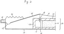
- a magnet cylinder 22 is attached on a lower plate 21 .
- a saucer-shaped upper plate 23 is further attached on the magnet 22 .
- the peripheral portion 21a of the lower plate 21 is formed so as to oppose the upper plate 23 with a gap 24 interposed therebetween.
- This exemplary loudspeaker is similar to the loudspeaker shown in Figure 1 in that the lower plate 21 , the magnet 22 , and the upper plate 23 constitute a magnetic circuit 32 including the gap 24 .
- a saucer-shaped frame 25 is attached onto the lower face of the lower plate 21 .
- the peripheral portion of the frame 25 is so formed as to receive a gasket 26 .
- the outer periphery of a diaphragm 28 is attached to the peripheral portion of the frame 25 by means of an edge 27 which in turn is fixed with the gasket 26 .
- the inner periphery of the diaphragm 28 is connected with a voice coil 29 .
- the voice coil 29 is inserted without being off-centered into the gap 24 formed between the lower plate 21 and the upper plate 23 .
- the diaphragm 28 is supported by the gasket 26 with a suspension 30 interposed therebetween.
- a dust cover 31 is formed so as to cover the upper plate 23 .
- the loudspeaker shown in Figure 2 has a basic structure similar to that of the loudspeaker shown in Figure 1 , but has a reduced thickness by accommodating the magnetic circuit 32 under the diaphragm 28 .
- Figure 3 shows a half cross section of an exemplary configuration for a conventional loudspeaker which has an improved configuration as compared with the loudspeaker shown in Figure 1 so as to achieve miniaturization and high performance.
- This loudspeaker incorporates a pot-shaped yoke 35 having an outer peripheral wall 35a , instead of the upper and lower plates used in the loudspeakers shown in Figures 1 and 2 .
- An inner peripheral wall 35b which is disposed concentrically with the outer peripheral wall 35a , is formed in the yoke 35 .
- a magnet ring 36 In the vicinity of the inner-upper end of the outer peripheral wall 35a of the yoke 35 is attached a magnet ring 36 .
- the magnet 36 may be a magnet which is, for example, composed of rare earth elements and is polarized in a radial direction
- a voice coil 9 is inserted into a gap 4 formed between the magnet 36 and the inner peripheral wall 35b .
- the yoke 35 , the magnet 36 , and the gap 4 constitute a magnetic circuit 37 .
- a high-performance loudspeaker such as shown in Figure 3 is likely to receive large input signals in actual use, so that the temperature of the voice coil 9 increases even more drastically.
- the heat generated by the temperature increase of the voice coil 9 is dissipated through the yoke 35 and/or the magnet 36 in the magnetic circuit 37 .
- the yoke 35 and the magnet 36 are miniaturized as a whole, thus such a heat dissipation is restrained.
- the voice coil 9 may be broken down due to the increase in the temperature thereof.
- the magnet is a magnet ring which is polarized in a radial direction.
- the magnet is selected from a group consisting of a samarium-cobalt magnet, a cerium-cobalt magnet and a neodymium magnet.
- the invention described herein makes possible the advantages of (1) providing a compact, thin, and yet high-performance loudspeaker apparatus capable of high-quality reproduction of an audio signal, and (2) a highly reliable loudspeaker apparatus having stable performance properties in which even when large input signals are continuously supplied thereto, any extraordinary increase in temperature of the voice coil is restrained.
- Figure 2 shows a half cross section of another exemplary configuration for a conventional loudspeaker.
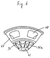
- Figure 6 is a perspective view of the loudspeaker in the second example of the present invention.
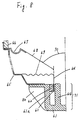
- Figure 9 shows a half cross section of a configuration for a loudspeaker in accordance with a fourth example of the present invention.
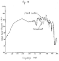
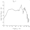
- Figure 10 is a graph which illustrates the exemplary frequency characteristic of the loudspeaker in accordance with the fourth example of the present invention.
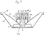
- a frame 42 so configurated as to surround the center pole 41a is attached to the supporter 41 .
- the frame 42 should preferably have the same properties as the supporter 41 . It is possible to integrally form the supporter 41 and the frame 42 when both are designed so as to be formed of the same material. This will make it possible to reduce the number of the component elements and fabrication steps of the loudspeaker, so that the fabrication process becomes more efficient and that the fabrication cost decreases. For example, it is preferable to integrally form the supporter 41 and the frame 42 by an aluminum die-casting method.
- the center pole 41a and the centering pin 43 may have any shape, e.g. a prism, a column, and a cylinder having a hollow portion.
- column shapes are preferable because they are easily fabricated and dissipate heat efficiently.
- a plurality of heat-dissipating fins may be integrally formed on the outside of the yoke 96 , as in the case of the loudspeaker of Example 3. In that case, it becomes possible to reduce the number of component elements and fabrication steps of the loudspeaker, so that the fabrication process becomes more efficient and the fabrication cost decreases, as in Example 3.
Landscapes
- Physics & Mathematics (AREA)
- Engineering & Computer Science (AREA)
- Acoustics & Sound (AREA)
- Signal Processing (AREA)
- Audible-Bandwidth Dynamoelectric Transducers Other Than Pickups (AREA)
Applications Claiming Priority (6)
| Application Number | Priority Date | Filing Date | Title |
|---|---|---|---|
| JP102308/93 | 1993-04-28 | ||
| JP10230893 | 1993-04-28 | ||
| JP10230893A JP3203876B2 (ja) | 1993-04-28 | 1993-04-28 | スピーカ |
| JP13449393A JP3218804B2 (ja) | 1993-06-04 | 1993-06-04 | スピーカ |
| JP134493/93 | 1993-06-04 | ||
| JP13449393 | 1993-06-04 |
Publications (3)
| Publication Number | Publication Date |
|---|---|
| EP0624049A2 true EP0624049A2 (fr) | 1994-11-09 |
| EP0624049A3 EP0624049A3 (fr) | 1995-03-08 |
| EP0624049B1 EP0624049B1 (fr) | 2002-06-12 |
Family
ID=26443024
Family Applications (1)
| Application Number | Title | Priority Date | Filing Date |
|---|---|---|---|
| EP19940106578 Expired - Lifetime EP0624049B1 (fr) | 1993-04-28 | 1994-04-27 | Appareil haut-parleur |
Country Status (2)
| Country | Link |
|---|---|
| EP (1) | EP0624049B1 (fr) |
| DE (1) | DE69430776T2 (fr) |
Cited By (13)
| Publication number | Priority date | Publication date | Assignee | Title |
|---|---|---|---|---|
| US5729617A (en) * | 1995-07-27 | 1998-03-17 | Nokia Technology Gmbh | Magnet system |
| GB2360899A (en) * | 1999-12-17 | 2001-10-03 | Goodmans Loudspeakers Ltd | Coaxial loudspeaker with the magnetic circuit mounted in front of the diaphragm |
| GB2375456A (en) * | 2001-02-20 | 2002-11-13 | Kh Technology Corp | Heat dissipating loudspeaker pole piece |
| GB2404520A (en) * | 2003-07-28 | 2005-02-02 | Turbosound Ltd | Phase plug equalizer used as heat sink for loudspeaker |
| US7016514B2 (en) | 2001-02-03 | 2006-03-21 | Kh Technology Corporation | Loudspeaker assembly |
| US7426283B2 (en) * | 2004-08-19 | 2008-09-16 | Pioneer Corporation | Speaker device and heat-dissipating member |
| US8989429B2 (en) | 2010-01-15 | 2015-03-24 | Phl Audio | Electrodynamic transducer having a dome and a buoyant hanging part |
| US9042594B2 (en) | 2010-01-15 | 2015-05-26 | Phl Audio | Electrodynamic transducer having a dome and an inner hanging part |
| US9084056B2 (en) | 2010-01-15 | 2015-07-14 | Phl Audio | Coaxial speaker system having a compression chamber with a horn |
| US9445201B2 (en) | 2013-11-21 | 2016-09-13 | Harman International Industries, Inc. | Inverted dual coil transducer |
| WO2016135517A3 (fr) * | 2015-02-27 | 2016-11-24 | Native Design Limited | Dispositif combiné de pilote de haut-parleur et de lumière |
| WO2019121072A1 (fr) * | 2017-12-19 | 2019-06-27 | Pss Belgium Nv | Haut-parleur |
| WO2020239766A1 (fr) * | 2019-05-29 | 2020-12-03 | Pss Belgium Nv | Haut-parleur |
Citations (9)
| Publication number | Priority date | Publication date | Assignee | Title |
|---|---|---|---|---|
| US3763334A (en) * | 1972-01-21 | 1973-10-02 | Gen Electric | Magnet assembly |
| DE3007991A1 (de) * | 1980-03-01 | 1981-09-17 | Elektrotechnik Ehmann Gmbh, 6953 Gundelsheim | Elektroakustischer wandler |
| US4327257A (en) * | 1979-09-10 | 1982-04-27 | Schwartz Leslie H | Alignment device for electro-acoustical transducers |
| US4379951A (en) * | 1977-04-20 | 1983-04-12 | Gabr Saad Z M | Electro-acoustic transducer means |
| DE3638693A1 (de) * | 1985-11-15 | 1987-05-21 | Bose Corp | Kompakter elektro-akustischer uebertrager |
| US4933975A (en) * | 1988-05-19 | 1990-06-12 | Electro-Voice, Inc. | Dynamic loudspeaker for producing high audio power |
| FR2667212A1 (fr) * | 1990-09-25 | 1992-03-27 | Phl Audio | Transducteur electroacoustique de puissance. |
| DE4126121A1 (de) * | 1991-08-07 | 1993-02-11 | Mac Audio Electronic Gmbh | Dynamischer lautsprecher |
| WO1993003586A1 (fr) * | 1991-08-05 | 1993-02-18 | Aura Systems, Inc. | Organe de commande de bobine mobile de haut-parleur |
-
1994
- 1994-04-27 DE DE1994630776 patent/DE69430776T2/de not_active Expired - Fee Related
- 1994-04-27 EP EP19940106578 patent/EP0624049B1/fr not_active Expired - Lifetime
Patent Citations (9)
| Publication number | Priority date | Publication date | Assignee | Title |
|---|---|---|---|---|
| US3763334A (en) * | 1972-01-21 | 1973-10-02 | Gen Electric | Magnet assembly |
| US4379951A (en) * | 1977-04-20 | 1983-04-12 | Gabr Saad Z M | Electro-acoustic transducer means |
| US4327257A (en) * | 1979-09-10 | 1982-04-27 | Schwartz Leslie H | Alignment device for electro-acoustical transducers |
| DE3007991A1 (de) * | 1980-03-01 | 1981-09-17 | Elektrotechnik Ehmann Gmbh, 6953 Gundelsheim | Elektroakustischer wandler |
| DE3638693A1 (de) * | 1985-11-15 | 1987-05-21 | Bose Corp | Kompakter elektro-akustischer uebertrager |
| US4933975A (en) * | 1988-05-19 | 1990-06-12 | Electro-Voice, Inc. | Dynamic loudspeaker for producing high audio power |
| FR2667212A1 (fr) * | 1990-09-25 | 1992-03-27 | Phl Audio | Transducteur electroacoustique de puissance. |
| WO1993003586A1 (fr) * | 1991-08-05 | 1993-02-18 | Aura Systems, Inc. | Organe de commande de bobine mobile de haut-parleur |
| DE4126121A1 (de) * | 1991-08-07 | 1993-02-11 | Mac Audio Electronic Gmbh | Dynamischer lautsprecher |
Cited By (21)
| Publication number | Priority date | Publication date | Assignee | Title |
|---|---|---|---|---|
| US5729617A (en) * | 1995-07-27 | 1998-03-17 | Nokia Technology Gmbh | Magnet system |
| GB2360899A (en) * | 1999-12-17 | 2001-10-03 | Goodmans Loudspeakers Ltd | Coaxial loudspeaker with the magnetic circuit mounted in front of the diaphragm |
| GB2360899B (en) * | 1999-12-17 | 2002-03-27 | Goodmans Loudspeakers Ltd | Coaxial speaker |
| US7016514B2 (en) | 2001-02-03 | 2006-03-21 | Kh Technology Corporation | Loudspeaker assembly |
| GB2375456A (en) * | 2001-02-20 | 2002-11-13 | Kh Technology Corp | Heat dissipating loudspeaker pole piece |
| GB2375456B (en) * | 2001-02-20 | 2004-08-11 | Kh Technology Corp | Loudspeaker pole piece and loudspeaker assembly |
| GB2404520A (en) * | 2003-07-28 | 2005-02-02 | Turbosound Ltd | Phase plug equalizer used as heat sink for loudspeaker |
| US7426283B2 (en) * | 2004-08-19 | 2008-09-16 | Pioneer Corporation | Speaker device and heat-dissipating member |
| US9084056B2 (en) | 2010-01-15 | 2015-07-14 | Phl Audio | Coaxial speaker system having a compression chamber with a horn |
| US9042594B2 (en) | 2010-01-15 | 2015-05-26 | Phl Audio | Electrodynamic transducer having a dome and an inner hanging part |
| US8989429B2 (en) | 2010-01-15 | 2015-03-24 | Phl Audio | Electrodynamic transducer having a dome and a buoyant hanging part |
| US9232301B2 (en) | 2010-01-15 | 2016-01-05 | Phl Audio | Coaxial speaker system having a compression chamber |
| US9445201B2 (en) | 2013-11-21 | 2016-09-13 | Harman International Industries, Inc. | Inverted dual coil transducer |
| WO2016135517A3 (fr) * | 2015-02-27 | 2016-11-24 | Native Design Limited | Dispositif combiné de pilote de haut-parleur et de lumière |
| US10219061B2 (en) | 2015-02-27 | 2019-02-26 | Native Design Limited | Light and loudspeaker driver device |
| EP3641331A1 (fr) * | 2015-02-27 | 2020-04-22 | Zuma Array Limited | Dispositif combiné de moteur de haut-parleur et de lumière |
| US10924832B2 (en) | 2015-02-27 | 2021-02-16 | Zuma Array Limited | Light and loudspeaker driver device |
| WO2019121072A1 (fr) * | 2017-12-19 | 2019-06-27 | Pss Belgium Nv | Haut-parleur |
| WO2020239766A1 (fr) * | 2019-05-29 | 2020-12-03 | Pss Belgium Nv | Haut-parleur |
| CN113906767A (zh) * | 2019-05-29 | 2022-01-07 | Pss比利时股份有限公司 | 扬声器 |
| US11924621B2 (en) | 2019-05-29 | 2024-03-05 | Pss Belgium Nv | Loudspeaker |
Also Published As
| Publication number | Publication date |
|---|---|
| DE69430776D1 (de) | 2002-07-18 |
| DE69430776T2 (de) | 2003-03-27 |
| EP0624049A3 (fr) | 1995-03-08 |
| EP0624049B1 (fr) | 2002-06-12 |
Similar Documents
| Publication | Publication Date | Title |
|---|---|---|
| EP0624049B1 (fr) | Appareil haut-parleur | |
| US5748760A (en) | Dual coil drive with multipurpose housing | |
| US7006653B2 (en) | Compact high performance speaker | |
| US6404896B1 (en) | Electric-acoustic transducer having dual voice coil drivers | |
| JP4237702B2 (ja) | デュアル・サスペンションを有するダイナミック・マイクロスピーカ | |
| US4552242A (en) | Coaxial type composite loudspeaker | |
| US20110311093A1 (en) | Micro-speaker | |
| US7020301B2 (en) | Loudspeaker | |
| JP2001086590A (ja) | 小型電気−音響変換器 | |
| US6870941B2 (en) | Dipole radiating dynamic speaker | |
| US7142685B2 (en) | Adjustable loudspeaker | |
| US4295011A (en) | Linear excursion-constant inductance loudspeaker | |
| US20100019584A1 (en) | Voice coil actuator | |
| JP2004502365A (ja) | 小型高性能スピーカ | |
| JPH11205897A (ja) | スピーカ | |
| US6219425B1 (en) | Loudspeaker with heat radiating hole and electrical device employing the same | |
| JP2003324793A (ja) | スピーカ装置及び振動板 | |
| JP3613881B2 (ja) | スピーカ | |
| JPS5864899A (ja) | ラウドスピ−カ | |
| KR20030083774A (ko) | 자화필름을 이용한 고정형 코일구조를 갖는 단방향/양방향전기-음향 변환기 및 전기-음향 변환 방법 | |
| JPH0614394A (ja) | スピーカ | |
| KR200284571Y1 (ko) | 자화필름을 이용한 고정형 코일구조를 갖는단방향/양방향 전기-음향 변환기 | |
| KR100267956B1 (ko) | 혼형 스피커 장치 | |
| JP2000013877A (ja) | スピーカ | |
| JPH06315195A (ja) | スピーカ |
Legal Events
| Date | Code | Title | Description |
|---|---|---|---|
| PUAI | Public reference made under article 153(3) epc to a published international application that has entered the european phase |
Free format text: ORIGINAL CODE: 0009012 |
|
| AK | Designated contracting states |
Kind code of ref document: A2 Designated state(s): DE FR GB |
|
| 17P | Request for examination filed |
Effective date: 19940927 |
|
| PUAL | Search report despatched |
Free format text: ORIGINAL CODE: 0009013 |
|
| AK | Designated contracting states |
Kind code of ref document: A3 Designated state(s): DE FR GB |
|
| 17Q | First examination report despatched |
Effective date: 19980407 |
|
| GRAG | Despatch of communication of intention to grant |
Free format text: ORIGINAL CODE: EPIDOS AGRA |
|
| GRAG | Despatch of communication of intention to grant |
Free format text: ORIGINAL CODE: EPIDOS AGRA |
|
| GRAH | Despatch of communication of intention to grant a patent |
Free format text: ORIGINAL CODE: EPIDOS IGRA |
|
| GRAH | Despatch of communication of intention to grant a patent |
Free format text: ORIGINAL CODE: EPIDOS IGRA |
|
| GRAA | (expected) grant |
Free format text: ORIGINAL CODE: 0009210 |
|
| AK | Designated contracting states |
Kind code of ref document: B1 Designated state(s): DE FR GB |
|
| REG | Reference to a national code |
Ref country code: GB Ref legal event code: FG4D |
|
| REF | Corresponds to: |
Ref document number: 69430776 Country of ref document: DE Date of ref document: 20020718 |
|
| ET | Fr: translation filed | ||
| PLBE | No opposition filed within time limit |
Free format text: ORIGINAL CODE: 0009261 |
|
| STAA | Information on the status of an ep patent application or granted ep patent |
Free format text: STATUS: NO OPPOSITION FILED WITHIN TIME LIMIT |
|
| 26N | No opposition filed |
Effective date: 20030313 |
|
| PGFP | Annual fee paid to national office [announced via postgrant information from national office to epo] |
Ref country code: FR Payment date: 20060410 Year of fee payment: 13 |
|
| PGFP | Annual fee paid to national office [announced via postgrant information from national office to epo] |
Ref country code: DE Payment date: 20060420 Year of fee payment: 13 |
|
| PGFP | Annual fee paid to national office [announced via postgrant information from national office to epo] |
Ref country code: GB Payment date: 20060426 Year of fee payment: 13 |
|
| GBPC | Gb: european patent ceased through non-payment of renewal fee |
Effective date: 20070427 |
|
| PG25 | Lapsed in a contracting state [announced via postgrant information from national office to epo] |
Ref country code: DE Free format text: LAPSE BECAUSE OF NON-PAYMENT OF DUE FEES Effective date: 20071101 |
|
| PG25 | Lapsed in a contracting state [announced via postgrant information from national office to epo] |
Ref country code: GB Free format text: LAPSE BECAUSE OF NON-PAYMENT OF DUE FEES Effective date: 20070427 |
|
| PG25 | Lapsed in a contracting state [announced via postgrant information from national office to epo] |
Ref country code: FR Free format text: LAPSE BECAUSE OF NON-PAYMENT OF DUE FEES Effective date: 20070430 |