EP0624049A2 - A loudspeaker apparatus - Google Patents
A loudspeaker apparatus Download PDFInfo
- Publication number
- EP0624049A2 EP0624049A2 EP94106578A EP94106578A EP0624049A2 EP 0624049 A2 EP0624049 A2 EP 0624049A2 EP 94106578 A EP94106578 A EP 94106578A EP 94106578 A EP94106578 A EP 94106578A EP 0624049 A2 EP0624049 A2 EP 0624049A2
- Authority
- EP
- European Patent Office
- Prior art keywords
- yoke
- magnet
- loudspeaker
- diaphragm
- voice coil
- Prior art date
- Legal status (The legal status is an assumption and is not a legal conclusion. Google has not performed a legal analysis and makes no representation as to the accuracy of the status listed.)
- Granted
Links
Images


Classifications
-
- H—ELECTRICITY
- H04—ELECTRIC COMMUNICATION TECHNIQUE
- H04R—LOUDSPEAKERS, MICROPHONES, GRAMOPHONE PICK-UPS OR LIKE ACOUSTIC ELECTROMECHANICAL TRANSDUCERS; DEAF-AID SETS; PUBLIC ADDRESS SYSTEMS
- H04R9/00—Transducers of moving-coil, moving-strip, or moving-wire type
- H04R9/02—Details
-
- H—ELECTRICITY
- H04—ELECTRIC COMMUNICATION TECHNIQUE
- H04R—LOUDSPEAKERS, MICROPHONES, GRAMOPHONE PICK-UPS OR LIKE ACOUSTIC ELECTROMECHANICAL TRANSDUCERS; DEAF-AID SETS; PUBLIC ADDRESS SYSTEMS
- H04R9/00—Transducers of moving-coil, moving-strip, or moving-wire type
- H04R9/02—Details
- H04R9/022—Cooling arrangements
-
- H—ELECTRICITY
- H04—ELECTRIC COMMUNICATION TECHNIQUE
- H04R—LOUDSPEAKERS, MICROPHONES, GRAMOPHONE PICK-UPS OR LIKE ACOUSTIC ELECTROMECHANICAL TRANSDUCERS; DEAF-AID SETS; PUBLIC ADDRESS SYSTEMS
- H04R9/00—Transducers of moving-coil, moving-strip, or moving-wire type
- H04R9/06—Loudspeakers
Definitions
- the present invention relates to a loudspeaker apparatus for use in various audio devices, and particularly to a thin, compact, and high-performance loudspeaker apparatus.
- Figure 1 shows a cross section of an exemplary configuration for a conventional loudspeaker. Since the loudspeaker is symmetrical about the central axis thereof, only a half portion of the cross section is shown in Figure 1 (referred to as a half cross section hereinafter).
- a magnet ring 2 is disposed on a saucer-shaped lower plate 1 .
- the lower plate 1 has a center pole 1a .
- a ring-shaped upper plate 3 is disposed on the magnet 2 .
- a gap 4 is formed between the center pole 1a and the upper plate 3 .
- a bowl-shaped frame 5 is attached on the upper face of the upper plate 3 .
- the outer periphery of a diaphragm 8 is attached to the circular peripheral portion of the frame 5 with an edge 7 interposed therebetween.
- the edge 7 is fixed onto the circular peripheral portion of the frame 5 by means of a gasket 6 .
- a voice coil 9 is inserted into the gap 4 without being off-centered.
- the voice coil 9 is connected with the inner periphery of the diaphragm 8 , and is supported by the frame 5 through a suspension 10 interposed therebetween, the suspension 10 being disposed in the vicinity of the middle portion of the voice coil 9 .
- a dome-shaped dust cover 11 is attached onto the upper surface of a central portion of the diaphragm 8 so as to prevent dust from entering the interior of the loudspeaker.
- Miniaturization and reduction in thickness of a conventional loudspeaker as shown in Figure 1 have been realized mainly by miniaturizing and reducing the thickness of each component element.
- a magnet cylinder 22 is attached on a lower plate 21 .
- a saucer-shaped upper plate 23 is further attached on the magnet 22 .
- the peripheral portion 21a of the lower plate 21 is formed so as to oppose the upper plate 23 with a gap 24 interposed therebetween.
- This exemplary loudspeaker is similar to the loudspeaker shown in Figure 1 in that the lower plate 21 , the magnet 22 , and the upper plate 23 constitute a magnetic circuit 32 including the gap 24 .
- a saucer-shaped frame 25 is attached onto the lower face of the lower plate 21 .
- the peripheral portion of the frame 25 is so formed as to receive a gasket 26 .
- the outer periphery of a diaphragm 28 is attached to the peripheral portion of the frame 25 by means of an edge 27 which in turn is fixed with the gasket 26 .
- the inner periphery of the diaphragm 28 is connected with a voice coil 29 .
- the voice coil 29 is inserted without being off-centered into the gap 24 formed between the lower plate 21 and the upper plate 23 .
- the diaphragm 28 is supported by the gasket 26 with a suspension 30 interposed therebetween.
- a dust cover 31 is formed so as to cover the upper plate 23 .
- the loudspeaker shown in Figure 2 has a basic structure similar to that of the loudspeaker shown in Figure 1 , but has a reduced thickness by accommodating the magnetic circuit 32 under the diaphragm 28 .
- Figure 3 shows a half cross section of an exemplary configuration for a conventional loudspeaker which has an improved configuration as compared with the loudspeaker shown in Figure 1 so as to achieve miniaturization and high performance.
- This loudspeaker incorporates a pot-shaped yoke 35 having an outer peripheral wall 35a , instead of the upper and lower plates used in the loudspeakers shown in Figures 1 and 2 .
- An inner peripheral wall 35b which is disposed concentrically with the outer peripheral wall 35a , is formed in the yoke 35 .
- a magnet ring 36 In the vicinity of the inner-upper end of the outer peripheral wall 35a of the yoke 35 is attached a magnet ring 36 .
- the magnet 36 may be a magnet which is, for example, composed of rare earth elements and is polarized in a radial direction
- a voice coil 9 is inserted into a gap 4 formed between the magnet 36 and the inner peripheral wall 35b .
- the yoke 35 , the magnet 36 , and the gap 4 constitute a magnetic circuit 37 .
- a high-performance loudspeaker such as shown in Figure 3 is likely to receive large input signals in actual use, so that the temperature of the voice coil 9 increases even more drastically.
- the heat generated by the temperature increase of the voice coil 9 is dissipated through the yoke 35 and/or the magnet 36 in the magnetic circuit 37 .
- the yoke 35 and the magnet 36 are miniaturized as a whole, thus such a heat dissipation is restrained.
- the voice coil 9 may be broken down due to the increase in the temperature thereof.
- the magnet is a magnet ring which is polarized in a radial direction.
- the magnet is selected from a group consisting of a samarium-cobalt magnet, a cerium-cobalt magnet and a neodymium magnet.
- the invention described herein makes possible the advantages of (1) providing a compact, thin, and yet high-performance loudspeaker apparatus capable of high-quality reproduction of an audio signal, and (2) a highly reliable loudspeaker apparatus having stable performance properties in which even when large input signals are continuously supplied thereto, any extraordinary increase in temperature of the voice coil is restrained.
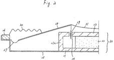
- Figure 2 shows a half cross section of another exemplary configuration for a conventional loudspeaker.
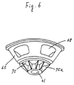
- Figure 6 is a perspective view of the loudspeaker in the second example of the present invention.
- Figure 9 shows a half cross section of a configuration for a loudspeaker in accordance with a fourth example of the present invention.
- Figure 10 is a graph which illustrates the exemplary frequency characteristic of the loudspeaker in accordance with the fourth example of the present invention.
- a frame 42 so configurated as to surround the center pole 41a is attached to the supporter 41 .
- the frame 42 should preferably have the same properties as the supporter 41 . It is possible to integrally form the supporter 41 and the frame 42 when both are designed so as to be formed of the same material. This will make it possible to reduce the number of the component elements and fabrication steps of the loudspeaker, so that the fabrication process becomes more efficient and that the fabrication cost decreases. For example, it is preferable to integrally form the supporter 41 and the frame 42 by an aluminum die-casting method.
- the center pole 41a and the centering pin 43 may have any shape, e.g. a prism, a column, and a cylinder having a hollow portion.
- column shapes are preferable because they are easily fabricated and dissipate heat efficiently.
- a plurality of heat-dissipating fins may be integrally formed on the outside of the yoke 96 , as in the case of the loudspeaker of Example 3. In that case, it becomes possible to reduce the number of component elements and fabrication steps of the loudspeaker, so that the fabrication process becomes more efficient and the fabrication cost decreases, as in Example 3.
Abstract
Description
- The present invention relates to a loudspeaker apparatus for use in various audio devices, and particularly to a thin, compact, and high-performance loudspeaker apparatus.
- In recent years, there has been increasing demand for a thin loudspeaker apparatus (simply referred to as a loudspeaker hereinafter) capable of high-quality sound reproduction, due to the diversified uses of loudspeakers and the various conditions under which loudspeakers are used.
- Figure 1 shows a cross section of an exemplary configuration for a conventional loudspeaker. Since the loudspeaker is symmetrical about the central axis thereof, only a half portion of the cross section is shown in Figure 1 (referred to as a half cross section hereinafter).
- As is shown in Figure 1, a
magnet ring 2 is disposed on a saucer-shaped lower plate 1. The lower plate 1 has a center pole 1a. A ring-shapedupper plate 3 is disposed on themagnet 2. Agap 4 is formed between the center pole 1a and theupper plate 3. Thus, the lower plate 1 and theupper plate 3 are layered and connected with each other, with themagnet 2 interposed therebetween, so as to constitute amagnetic circuit 12 including thegap 4. - On the upper face of the
upper plate 3, a bowl-shaped frame 5 is attached. The outer periphery of adiaphragm 8 is attached to the circular peripheral portion of theframe 5 with anedge 7 interposed therebetween. Theedge 7 is fixed onto the circular peripheral portion of theframe 5 by means of a gasket 6. On the other hand, avoice coil 9 is inserted into thegap 4 without being off-centered. Thevoice coil 9 is connected with the inner periphery of thediaphragm 8, and is supported by theframe 5 through asuspension 10 interposed therebetween, thesuspension 10 being disposed in the vicinity of the middle portion of thevoice coil 9. Furthermore, a dome-shaped dust cover 11 is attached onto the upper surface of a central portion of thediaphragm 8 so as to prevent dust from entering the interior of the loudspeaker. - Miniaturization and reduction in thickness of a conventional loudspeaker as shown in Figure 1 have been realized mainly by miniaturizing and reducing the thickness of each component element.
- Figure 2 shows a half cross section of an exemplary conventional loudspeaker in which thickness has been reduced.
- According to this conventional loudspeaker, a
magnet cylinder 22 is attached on alower plate 21. A saucer-shapedupper plate 23 is further attached on themagnet 22. The peripheral portion 21a of thelower plate 21 is formed so as to oppose theupper plate 23 with agap 24 interposed therebetween. This exemplary loudspeaker is similar to the loudspeaker shown in Figure 1 in that thelower plate 21, themagnet 22, and theupper plate 23 constitute amagnetic circuit 32 including thegap 24. - In the exemplary loudspeaker shown in Figure 2, a saucer-
shaped frame 25 is attached onto the lower face of thelower plate 21. The peripheral portion of theframe 25 is so formed as to receive agasket 26. The outer periphery of adiaphragm 28 is attached to the peripheral portion of theframe 25 by means of anedge 27 which in turn is fixed with thegasket 26. The inner periphery of thediaphragm 28 is connected with a voice coil 29. The voice coil 29 is inserted without being off-centered into thegap 24 formed between thelower plate 21 and theupper plate 23. Thediaphragm 28 is supported by thegasket 26 with asuspension 30 interposed therebetween. A dust cover 31 is formed so as to cover theupper plate 23. - The loudspeaker shown in Figure 2 has a basic structure similar to that of the loudspeaker shown in Figure 1, but has a reduced thickness by accommodating the
magnetic circuit 32 under thediaphragm 28. - Figure 3 shows a half cross section of an exemplary configuration for a conventional loudspeaker which has an improved configuration as compared with the loudspeaker shown in Figure 1 so as to achieve miniaturization and high performance.
- This loudspeaker incorporates a pot-
shaped yoke 35 having an outerperipheral wall 35a, instead of the upper and lower plates used in the loudspeakers shown in Figures 1 and 2. An inner peripheral wall 35b, which is disposed concentrically with the outerperipheral wall 35a, is formed in theyoke 35. In the vicinity of the inner-upper end of the outerperipheral wall 35a of theyoke 35 is attached amagnet ring 36. Themagnet 36 may be a magnet which is, for example, composed of rare earth elements and is polarized in a radial direction Avoice coil 9 is inserted into agap 4 formed between themagnet 36 and the inner peripheral wall 35b. Theyoke 35, themagnet 36, and thegap 4 constitute amagnetic circuit 37. - The other component elements of the loudspeaker shown in Figure 3, e.g. a
frame 5 and adiaphragm 8, are similar to those in the loudspeakers shown in Figure 1, and descriptions thereof are omitted. Those component elements are indicated by the same reference numerals in Figure 1. - According to the loudspeaker shown in Figure 3, a compact, light, and high-performance
magnetic circuit 37 is realized by using a rare earth magnetic for themagnet 36 in which the rare earth magnet is polarized in the radial direction. As a result, the loudspeaker is miniaturized and has high performance over all. - However, the conventional loudspeakers shown in Figures 1 to 3 have the following problems regarding miniaturization, reduction in thickness, and improvement in sound reproduction quality:
- According to the configuration shown in Figure 1, one can further miniaturize the loudspeaker by making the tilt of the
diaphragm 8 gentler. Alternatively, the loudspeaker can also be miniaturized by reducing the respective thicknesses of the lower plate 1, themagnet 2, and theupper plate 3 so as to reduce the thickness of themagnetic circuit 12 as a whole. However, too gentle a tilt of thediaphragm 8 brings such problems as of the decrease in the upper limit of reproducible frequency in the high frequency region and of uneven frequency characteristics. Moreover, as the thickness of themagnetic circuit 12 is reduced, the movement of thevoice coil 9 may be limited and/or the sound-reproduction efficiency may decrease, thus deteriorating the quality of reproduced sounds. - On the other hand, according to the configuration shown in Figure 2, the
diaphragm 28 has an upside-down shape called "a reverse cone type" as compared with common loudspeakers, while the thickness of the loudspeaker is reduced. As a result, the pressure of the reproduced sound overly diffuses, thus causing a decrease in the sound reproduction efficiency and deterioration in the reproduction characteristics of the audio signals along the center axis of the loudspeaker. This inevitably limits the usage of the loudspeaker. In addition, thediaphragm 28 is supported less firmly and therefore is likely to become insecure, which disables the loudspeaker from reproducing audio signals of large energy. - According to the configurations of conventional loudspeakers, there is a tendency for the temperature of the
voice coil 9 or 29 to gradually increase when input signals of large energy (simply referred to as large input signals hereinafter) are continuously input to the loudspeaker. - In particular, a high-performance loudspeaker such as shown in Figure 3 is likely to receive large input signals in actual use, so that the temperature of the
voice coil 9 increases even more drastically. The heat generated by the temperature increase of thevoice coil 9 is dissipated through theyoke 35 and/or themagnet 36 in themagnetic circuit 37. However, according to the configuration shown in Figure 3, theyoke 35 and themagnet 36 are miniaturized as a whole, thus such a heat dissipation is restrained. As a result, in extreme cases, thevoice coil 9 may be broken down due to the increase in the temperature thereof. - A configuration which can solve the above-mentioned problems is required in order to satisfy the demand for miniaturization, reduction in size, and high performance for the loudspeaker at the same time.
- A loudspeaker apparatus according to the present invention comprises a supporting member having a center pole; a frame, the outer periphery of the frame connected with the supporting member; a yoke having a pot-like shape, the yoke including an outer peripheral wall and an inner peripheral wall, the walls being formed concentrically with each other, the yoke being attached at the top end of the center pole so as to face the supporting member; a magnet attached to the inner side face of the outer peripheral wall; a voice coil inserted into a gap between the magnet and the inner peripheral wall, the voice coil moved along the direction of the center axis of the yoke by interaction between a magnetic field formed by the magnet and a current flowing through the voice coil; and a diaphragm disposed between the supporting member and the yoke so as to surround the center pole, the inner periphery of the diaphragm connected with the voice coil, the outer periphery of the diaphragm connected with the outer periphery of the frame, the diaphragm moving in accordance with movement of the voice coil.
- In one embodiment, a projected area of the yoke on the diaphragm is a half or less of the effective area of the diaphragm. Preferably, the yoke acts as an equalizer and has a shape and size sufficient for obtaining an appropriate equalizing effect.
- In another embodiment, the magnet is a magnet ring which is polarized in a radial direction. Preferably, the magnet is selected from a group consisting of a samarium-cobalt magnet, a cerium-cobalt magnet and a neodymium magnet.
- In still another embodiment, the speaker apparatus further comprises a heat dissipating means for dissipating heat generated in the voice coil and the yoke. The heat dissipating means may be a heat dissipating member which has a plurality of heat dissipating fins. Alternatively, the heat dissipating means is a plurality of heat dissipating fins which are formed as part of the yoke.
- A loudspeaker apparatus according to the present invention comprises a yoke having a pot-like shape, the yoke including an outer peripheral wall and an inner peripheral wall, the walls being formed concentrically with each other; a frame disposed in front of the yoke, the inner periphery of the frame connected with the yoke; a magnet attached to the inner side face of the outer peripheral wall; a voice coil inserted into a gap between the magnet and the inner peripheral wall, the voice coil moved along the direction of the center axis of the yoke by interaction between a magnetic field formed by the magnet and a current flowing through the voice coil; a diaphragm, the inner periphery of the diaphragm connected with the voice coil, the outer periphery of the diaphragm connected with the outer periphery of the frame, the diaphragm moving in accordance with movement of the voice coil; and a heat dissipating means for dissipating heat generated in the voice coil and the yoke.
- In one embodiment, wherein the heat dissipating means is a heat dissipating member which has a plurality of heat dissipating fins. Alternatively, the heat dissipating means may be a plurality of heat dissipating fins which are formed as part of the yoke.
- In another embodiment, the magnet is a magnet ring which is polarized in a radial direction. Preferably, the magnet is selected from a group consisting of a samarium-cobalt magnet, a cerium-cobalt magnet and a neodymium magnet.
- Thus, the invention described herein makes possible the advantages of (1) providing a compact, thin, and yet high-performance loudspeaker apparatus capable of high-quality reproduction of an audio signal, and (2) a highly reliable loudspeaker apparatus having stable performance properties in which even when large input signals are continuously supplied thereto, any extraordinary increase in temperature of the voice coil is restrained.
- These and other advantages of the present invention will become apparent to those skilled in the art upon reading and understanding the following detailed description with reference to the accompanying figures.
- Figure 1 shows a half cross section of an exemplary configuration for a conventional loudspeaker.
- Figure 2 shows a half cross section of another exemplary configuration for a conventional loudspeaker.
- Figure 3 shows a half cross section of still another exemplary configuration for a conventional loudspeaker.
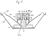
- Figure 4 is a cross-sectional view showing a configuration for a loudspeaker in accordance with a first example of the present invention.
- Figure 5 shows a half cross section of a configuration for a loudspeaker in accordance with a second example of the present invention.
- Figure 6 is a perspective view of the loudspeaker in the second example of the present invention.
- Figures 7A to 7D are perspective views showing heat dissipators having different shapes which may be used for a loudspeaker in accordance with the present invention.
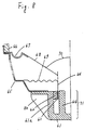
- Figure 8 shows a half cross section of a configuration for a loudspeaker in accordance with a third example of the present invention.
- Figure 9 shows a half cross section of a configuration for a loudspeaker in accordance with a fourth example of the present invention.
- Figure 10 is a graph which illustrates the exemplary frequency characteristic of the loudspeaker in accordance with the fourth example of the present invention.
- Figure 11 is a graph which illustrates the influence of the size of a magnetic circuit portion on the frequency characteristic of the loudspeaker in accordance with the fourth example of the present invention.
- Hereinafter, the present invention will be described by way of examples, with reference to the accompanying drawings.
- Figure 4 shows a cross section of a loudspeaker in accordance with a first example of the present invention.
- The loudspeaker shown in Figure 4 includes a disk-shaped
supporter 41 instead of the upper plate 1 and thelower plate 3 which conventional loudspeakers typically have. In the center of thesupporter 41, there is integrally formed acenter pole 41a extending toward the front face of the loudspeaker. Thesupporter 41 and thecenter pole 41a may alternatively be formed separately and attached to each other later. - At the top end of the
center pole 41a, a centeringpin 43 is formed. It is preferable to fabricate the centeringpin 43 with a high precision as to measurements thereof. This is because, as will be described later, ayoke 44 is to be fixed by inserting the centeringpin 43 into acenter guide hole 45 of theyoke 44. - The
supporter 41 is preferably a non-magnetic material having high physical strength and with a high heat dissipating property. For example, thesupporter 41 may be formed by an aluminum die-casting method, a zinc die-casting method and the like. However, if the loudspeaker is to be used without a large signal being input, thesupporter 41 may be formed of a heat-resistant resin such as any so-called engineering plastics because the heat dissipating property is not strongly required in such a case. - A frame 42 so configurated as to surround the
center pole 41a is attached to thesupporter 41. The frame 42 should preferably have the same properties as thesupporter 41. It is possible to integrally form thesupporter 41 and the frame 42 when both are designed so as to be formed of the same material. This will make it possible to reduce the number of the component elements and fabrication steps of the loudspeaker, so that the fabrication process becomes more efficient and that the fabrication cost decreases. For example, it is preferable to integrally form thesupporter 41 and the frame 42 by an aluminum die-casting method. - The
center pole 41a and the centeringpin 43 may have any shape, e.g. a prism, a column, and a cylinder having a hollow portion. However, column shapes are preferable because they are easily fabricated and dissipate heat efficiently. - The
yoke 44 has a pot-like shape enclosed by an outer peripheral wall 44a. In the vicinity of the center of the bottom face of theyoke 44, thecenter guide hole 45 surrounded by an inner peripheral wall 44b is formed. The inner peripheral wall 44b and the outer peripheral wall 44a are formed concentrically with each other. In the vicinity of the inner-lower end of the outer peripheral wall 44a of theyoke 44, a magnet ring 46 is attached. Avoice coil 48 is inserted into a gap 47 between the magnet 46 and the wall surface of the inner wall 44b. Theyoke 44, the magnet 46, and the gap 47 constitute amagnetic circuit 53. - The outer periphery of the frame 42 is connected with the outer periphery of a
diaphragm 50 with anedge 49 interposed therebetween. The inner periphery of thediaphragm 50 is connected with thevoice coil 48. One edge of asuspension 51 is further connected with thevoice coil 48. The other edge of thesuspension 51 is attached to the frame 42 and is supported on the upper face of thesupporter 41. Aflexible dust cover 52 is provided between thediaphragm 50 and the magnet 46. A ring gasket (not shown) may be attached to the outer periphery of the frame 42. - In an actual operation of the loudspeaker, a current in accordance with an audio signal to be output flows through the
voice coil 48. The current and a magnetic field formed by the magnet 46 interact with each other so as to produce force by which thevoice coil 48 is moved upwards and downwards in the gap 47 (i.e., along the direction of the center axis of the yoke 44). This movement of thevoice coil 48 is transmitted to thediaphragm 50 and consequently,diaphragm 50 vibrates so as to reproduce audio signals. - In the fabrication process of the loudspeaker shown in Figure 4, the
suspension 51, thediaphragm 50, and thevoice coil 48 are successively disposed around thecenter pole 41a formed on thesupporter 41. Next, the respective inner peripheries of thediaphragm 50 and thesuspension 51 are fixed to thevoice coil 48, and their respective outer peripheries are fixed to the frame 42, by using an adhesive, while ensuring that the centers of thediaphragm 50 and thesuspension 51 coincide with each other by means of the centeringpin 43. Last of all, theyoke 44, on which the magnet 46 has been mounted, is fixed by inserting the centeringpin 43 into thecenter guide hole 45 of theyoke 44. - The
yoke 44 is required to have such properties as low magnetic resistance and high heat dissipation, and preferably is composed of iron with a high magnetic permeability. For material of thediaphragm 50, molded pulp or molded plastic may be typically used. Thesuspension 51 may be typically made of pressed texture. - As is described above, in the loudspeaker shown in Figure 4, the
magnetic circuit 53, which conventionally is placed behind thediaphragm 50, is disposed in front of thediaphragm 50. Thus, it is made possible to reduce the thickness of the loudspeaker. - The configuration shown in Figure 4 may have an unfavorable effect on performance properties of the loudspeaker and the quality of reproduced sounds if the
magnetic circuit 53 is too large. However, the inventors found through experiments that deterioration of the performance properties and the reproduced sounds can be restrained by reducing the projected area of the magnetic circuit 53 (practically, the yoke 44) on thediaphragm 50 to be a half or less of the effective area of thediaphragm 50. - In order to satisfy the above-mentioned conditions, a rare earth magnet having a high energy density is used for the magnet 46 in the loudspeaker of the present example. In addition, the magnet 46 is polarized in a radial direction, thereby realizing a compact, light, and very powerful
magnetic circuit 53. Specifically, a samarium-cobalt magnet, a cerium-cobalt magnet and a neodymium magnet and the like are preferably used as the magnet 46. In particular, the neodymium magnet is preferable. - As has been described, in the loudspeaker of the first example of the invention, the thickness of the loudspeaker is reduced by disposing the
magnetic circuit 53 in front of thediaphragm 50 as is shown in Figure 4. In addition, high-quality reproduction of audio signals is realized by optimizing the size of themagnetic circuit 53. In contrast to the conventional loudspeaker described with reference to Figure 2, the reduction in thickness of the loudspeaker can be realized without unfavorably affecting the design of the moving system of the loudspeaker. Accordingly, the loudspeaker can be optimized both in terms of the configuration of the moving system and the quality of the reproduced sounds. - Moreover, the
magnetic circuit 53 disposed in front of thediaphragm 50 can also function as an equalizer. Taking advantage of this aspect, the frequency characteristics of the loudspeakers can be controlled (this effect will hereinafter be referred to as an "equalizing effect"). As a result, by optimizing the size and shape of the magnet circuit 53 (practically, the yoke 44), frequency characteristics can be improved especially in middle to high frequency bands, whereby a loudspeaker capable of reproducing sounds with an improved quality can be provided. This equalizing effect will be further described later with reference to the drawings. - Typical dimensions of the
supporter 41, thediaphragm 50 and theyoke 44 are as follows: the diameter of the supporter 41: 81 mm; the diameter of thecenter pole 41a: 24 mm; the height of thecenter pole 41a: 50 mm; the diameter of the diaphragm 50: 135 mm; the diameter of the bottom face of the yoke 44: 41 mm; the height of the outer and inner peripheral walls 44a and 44b: 20 mm. - In the loudspeaker shown in Figure 4, the
flexible dust cover 52 is provided between the magnet 46 and thediaphragm 50 so as to prevent dust, etc. from entering the interior of the loudspeaker. However, such adust cover 52 is not required if environments permit. - A configuration in which improvements are made with a view mainly to reducing the thickness of a loudspeaker was described in Example 1. Hereinafter, a second example of the present invention will be described with reference to Figures 5 to 7. The loudspeaker of the present example is intended to have an improved heat dissipation property.
- Figure 5 shows a half cross section of a configuration for a loudspeaker according to the second example of the present invention.
- The loudspeaker shown in Figure 5 incorporates a pot-shaped
yoke 61 enclosed by an outerperipheral wall 61a. An inner peripheral wall 61b is also formed concentrically with the outerperipheral wall 61a in theyoke 61. In the vicinity of the inner-upper end of the outerperipheral wall 61a of theyoke 61, a rareearth magnet ring 62 polarized in a radial direction is attached. Avoice coil 64 is inserted into agap 63 between themagnet 62 and the inner peripheral wall 61b. Theyoke 61, themagnet 62, and thegap 63 constitute a magnetic circuit 71. - A bowl-shaped
frame 65 is attached to the outer-upper end of the outerperipheral wall 61a of theyoke 61. The outer periphery of adiaphragm 68 is connected with the circular peripheral portion of theframe 65 with anedge 67 interposed therebetween, theedge 67 being fixed by means of a gasket 66. The inner periphery of thediaphragm 68 is connected with thevoice coil 64. Thevoice coil 64 is further supported by asuspension 69 provided in the vicinity of the center thereof. A dome-shapeddust cover 70 is provided above the central portion of thediaphragm 68 so as to prevent dust from entering the interior of the loudspeaker. - One major feature of the loudspeaker in the present example is a
heat dissipator 75 attached on the outside of theyoke 61. Several dissipatingfins 75a are provided on theheat dissipator 75 so as to increase the surface area, whereby the heat dissipation property is improved. - Figure 6 is a perspective view showing the loudspeaker shown in Figure 5.
- As is described above, the temperature of the
voice coil 64 increases when large signals are continuously input to the loudspeaker, and consequently the temperature of the magnetic circuit 71 increases. The loudspeaker shown in Figures 5 and 6 includes a small magnetic circuit 71 utilizing a rare earth magnet polarized in the radial direction. Therefore, the thermal capacity of the magnetic circuit 71 is smaller than that of the conventional loudspeaker, which is likely to cause a temperature elevation therein. However, the heat is effectively dissipated via the plurality of dissipatingfins 75a of theheat dissipator 75 attached on theyoke 61, so that any extraordinary increase in the temperature of thevoice coil 64 is not sustained. As a result, problems concerning the performance properties of the loudspeaker due to increases in the temperature of thevoice coil 64 are prevented, and a highly reliable loudspeaker having a stable performance properties is realized. - Figures 7A to 7D show examples of the
heat dissipator 75 with various shapes that can be suitably used for the loudspeaker in the present example. The heat dissipator shown in Figure 7A is identical with that shown in Figures 5 and 6. - The
heat dissipator 75 is composed of a material having high thermal conductivity, e.g. aluminum, iron, and zinc alloys. For example, theheat dissipator 75 in the present example is formed by an aluminum die-casting method. The size and shape of theheat dissipator 75 may be designed so as to be optimum based on the size and shape of the loudspeaker. The estimated value for the increased temperature of thevoice coil 64, which would be calculated from the conditions of signals to be input, may also be taken into account for designing theheat dissipator 75. Accordingly, the shape of theheat dissipator 75 to be used for the loudspeaker of the present example is not limited to those shown in Figures 7A to 7D, as long as the heat generated in thevoice coil 64 is well dissipated. - Hereinafter, a loudspeaker in a third example of the present invention will be described with reference to Figure 8, which shows a half cross section of the loudspeaker of the present example. In the loudspeaker of the present example, improvements are made with a view mainly to improving the heat dissipation property thereof.
- In Example 2, the
heat dissipator 75 is attached on the outside of theyoke 61. Instead of that, a plurality of heat-dissipatingfins 80 are integrally formed on the outside of ayoke 61 in this example. The other component elements are similar to those of the loudspeaker in Example 2, and descriptions thereof are omitted. - According to the loudspeaker shown in Figure 8, the temperature of a
voice coil 64 is prevented from increasing extraordinarily, as is the case with the loudspeaker of Example 2. In addition, the heat-dissipatingfins 80 and theyoke 61 are formed integrally. Therefore, it is possible to reduce the number of the component elements and fabrication steps of the loudspeaker, so that the fabrication process becomes more efficient and that the fabrication cost decreases. - Hereinafter, a loudspeaker according to a fourth example of the present invention will be described with reference to Figure 9, which shows a half cross section of the loudspeaker of the present example. In the loudspeaker of the present example, as in Examples 2 and 3, improvements are made with a view to improving the heat dissipation property thereof in addition to the improvements to reduce the thickness of the loudspeaker by disposing the magnetic circuit in front of the diaphragm as in Example 1.
- According to a configuration shown in Figure 9, a disk-shaped
supporter 91 having acenter pole 91a in a central portion is used. Thecenter pole 91a is formed in a cylindrical shape having a hollow portion. A bowl-shapedframe 93 is attached on thesupporter 91 by means ofscrews 92. - A centering
pin 94 is formed at the top end of thecenter pole 91a. The centeringpin 94, as well as the centeringpole 91a, has a hollow portion so as to receive ascrew 95 for fixing ayoke 96. - The
yoke 96 has a similar configuration to that of theyoke 44 of Example 1, shown in Figure 4. In other words, theyoke 96 has an inner peripheral wall 96b so as to form acenter guide hole 97. An outer peripheral wall 96a is also formed concentrically with the inner peripheral wall 96b. Theyoke 96 is fixed to thecenter pole 91a by inserting the centeringpin 94 into thecenter guide hole 97 of theyoke 96, with use of thescrew 95. - In the vicinity of the inner-lower end of the outer peripheral wall 96a of the
yoke 96, amagnet ring 98 is attached. Avoice coil 100 is inserted into agap 99 between themagnet 98 and the wall surface of the inner peripheral wall 96b. Theyoke 96, themagnet 98, and thegap 99 constitute a magnetic circuit 106. - By using a rare earth magnet polarized in a radial direction as the
magnet 98, similar to Examples 1 to 3, the magnetic circuit 106 becomes compact, light, and very powerful. Preferably, a neodymium magnet is used. - The outer periphery of the
frame 93 is processed so as to receive agasket 101, and is connected with the outer periphery of thediaphragm 103, with anedge 102 interposed therebetween, theedge 102 being fixed by means of agasket 101. The inner periphery of thediaphragm 103 is connected with thevoice coil 100. One end of asuspension 104 is further connected with thevoice coil 100, while the other end of thesuspension 104 is supported by theframe 93. Aflexible dust cover 105 is provided between thediaphragm 103 and themagnet 98. However, thedust cover 105 is not a requirement if environments permit. - Moreover, a
heat dissipator 110 is attached on the outside of theyoke 96, as in Example 2. Several heat-dissipating fins 110a are provided on theheat dissipator 110 so as to improve the dissipation property for heat generated in thevoice coil 100 and the magnetic circuit 106. Particularly in this example, the vibration of thediaphragm 103 stirs air in the neighborhood of theheat dissipator 110. Thus, the heat dissipation can be enhanced. - The loudspeaker having the above-mentioned configuration has both the features of the loudspeaker in Example 1 and the features of the loudspeaker in Example 2. In other words, the thickness of the loudspeaker is reduced by disposing the magnetic circuit 106 in front of the
diaphragm 103. The magnetic circuit 106 is made compact and powerful by using a rare earth magnet polarized in a radial direction as themagnet 98. In addition, even when large signals are continuously input to the loudspeaker, theheat dissipator 110 prevents the temperature of thevoice coil 100 from any extraordinary or damaging increase. - Moreover, the loudspeaker in the present example can utilize the equalizing effect of the magnetic circuit 106 as in Example 1, shown in Figure 4. Particular in the present example, the size and shape of the plurality of heat-dissipating fins 110a of the
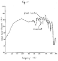
heat dissipator 110 can be varied so as to control the equalizing effect flexibly. As a result, more varied frequency characteristics than those of the loudspeaker of Example 1 can be obtained. - Figure 10 shows an example of frequency characteristics of the loudspeaker having the configuration according to the present example. The solid line denotes the frequency characteristic (the relationship between frequency and output sound pressure) of the loudspeaker of the present example (the projected area of the magnetic circuit 106 on the
diaphragm 103 is 10% of the effective area thereof), whereas the broken line denotes the frequency characteristic of a conventional loudspeaker in which the magnetic circuit is located behind the diaphragm. As is seen from Figure 10, the loudspeaker of the present example has higher output sound pressure, i.e. output level of the reproduced sound volume, than the conventional loudspeaker, especially in the middle to high frequency bands. - More diversity in the equalizing effect can be attained by varying the thickness, size, and number of the heat-dissipating fins 110a of the
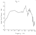
heat dissipator 110. In addition, the equalizing effect can be further improved by integrally forming the heat-dissipating fins 110a at the periphery of theheat dissipator 110. - Attention has to be paid to the fact that such a configuration of the loudspeaker in the present example may have an unfavorable effect on performance properties of the loudspeaker when the projected area of the magnetic circuit 106 on the
diaphragm 103 exceeds a half of the effective area of thediaphragm 103. Figure 11 shows such an unfavorable frequency characteristic obtained when the projected area of the magnetic circuit 106 on thediaphragm 103 is 70% of the effective area of thediaphragm 103. In Figure 11, peaks exist in middle frequency band in the frequency characteristic, resulting in less flatness thereof. Such peaks result from interference caused by the reflected sound from the magnetic circuit 106. - However, as described previously relating to the first example of the present invention, the above unfavorable effect can be avoided by making the projected area of the magnetic circuit 106 on the diaphragm 103 a half or less of the effective area of the
diaphragm 103. - In stead of the
heat dissipator 110, a plurality of heat-dissipating fins may be integrally formed on the outside of theyoke 96, as in the case of the loudspeaker of Example 3. In that case, it becomes possible to reduce the number of component elements and fabrication steps of the loudspeaker, so that the fabrication process becomes more efficient and the fabrication cost decreases, as in Example 3. - Various other modifications will be apparent to and can be readily made by those skilled in the art without departing from the scope and spirit of this invention. Accordingly, it is not intended that the scope of the claims appended hereto be limited to the description as set forth herein, but rather that the claims be broadly construed.
Claims (13)
- A loudspeaker apparatus comprising:
a supporting member having a center pole;
a frame, the outer periphery of said frame connected with said supporting member;
a yoke having a pot-like shape, said yoke including an outer peripheral wall and an inner peripheral wall, said walls being formed concentrically with each other, said yoke being attached at the top end of said center pole so as to face said supporting member;
a magnet attached to the inner side face of said outer peripheral wall;
a voice coil inserted into a gap between said magnet and said inner peripheral wall, said voice coil moved along the direction of the center axis of said yoke by interaction between a magnetic field formed by said magnet and a current flowing through said voice coil; and
a diaphragm disposed between said supporting member and said yoke so as to surround said center pole, the inner periphery of said diaphragm connected with said voice coil, the outer periphery of said diaphragm connected with the outer periphery of said frame, said diaphragm moving in accordance with movement of said voice coil. - A loudspeaker apparatus according to claim 1, wherein a projected area of said yoke on said diaphragm is a half or less of the effective area of said diaphragm.
- A loudspeaker apparatus according to claim 2, wherein said yoke acts as an equalizer and has a shape and size sufficient for obtaining an appropriate equalizing effect.
- A loudspeaker apparatus according to claim 1, wherein said magnet is a magnet ring which is polarized in a radial direction.
- A loudspeaker apparatus according to claim 4, wherein said magnet is selected from a group consisting of a samarium-cobalt magnet, a cerium-cobalt magnet and a neodymium magnet.
- A loudspeaker apparatus according to claim 1, further comprising a heat dissipating means for dissipating heat generated in said voice coil and said yoke.
- A loudspeaker apparatus according to claim 6, wherein said heat dissipating means is a heat dissipating member which has a plurality of heat dissipating fins.
- A loudspeaker apparatus according to claim 6, wherein said heat dissipating means is a plurality of heat dissipating fins which are formed as part of said yoke.
- A loudspeaker apparatus comprising:
a yoke having a pot-like shape, said yoke including an outer peripheral wall and an inner peripheral wall, said walls being formed concentrically with each other;
a frame disposed in front of said yoke, the inner periphery of said frame connected with said yoke;
a magnet attached to the inner side face of said outer peripheral wall;
a voice coil inserted into a gap between said magnet and said inner peripheral wall, said voice coil moved along the direction of the center axis of said yoke by interaction between a magnetic field formed by said magnet and a current flowing through said voice coil;
a diaphragm, the inner periphery of said diaphragm connected with said voice coil, the outer periphery of said diaphragm connected with the outer periphery of said frame, said diaphragm moving in accordance with movement of said voice coil; and
a heat dissipating means for dissipating heat generated in said voice coil and said yoke. - A loudspeaker apparatus according to claim 9, wherein said heat dissipating means is a heat dissipating member which has a plurality of heat dissipating fins.
- A loudspeaker apparatus according to claim 9, wherein said heat dissipating means is a plurality of heat dissipating fins which are formed as part of said yoke.
- A loudspeaker apparatus according to claim 9, wherein said magnet is a magnet ring which is polarized in a radial direction.
- A loudspeaker apparatus according to claim 12, wherein said magnet is selected from a group consisting of a samarium-cobalt magnet, a cerium-cobalt magnet and a neodymium magnet.
Applications Claiming Priority (6)
| Application Number | Priority Date | Filing Date | Title |
|---|---|---|---|
| JP10230893A JP3203876B2 (en) | 1993-04-28 | 1993-04-28 | Speaker |
| JP10230893 | 1993-04-28 | ||
| JP102308/93 | 1993-04-28 | ||
| JP13449393 | 1993-06-04 | ||
| JP13449393A JP3218804B2 (en) | 1993-06-04 | 1993-06-04 | Speaker |
| JP134493/93 | 1993-06-04 |
Publications (3)
| Publication Number | Publication Date |
|---|---|
| EP0624049A2 true EP0624049A2 (en) | 1994-11-09 |
| EP0624049A3 EP0624049A3 (en) | 1995-03-08 |
| EP0624049B1 EP0624049B1 (en) | 2002-06-12 |
Family
ID=26443024
Family Applications (1)
| Application Number | Title | Priority Date | Filing Date |
|---|---|---|---|
| EP19940106578 Expired - Lifetime EP0624049B1 (en) | 1993-04-28 | 1994-04-27 | A loudspeaker apparatus |
Country Status (2)
| Country | Link |
|---|---|
| EP (1) | EP0624049B1 (en) |
| DE (1) | DE69430776T2 (en) |
Cited By (13)
| Publication number | Priority date | Publication date | Assignee | Title |
|---|---|---|---|---|
| US5729617A (en) * | 1995-07-27 | 1998-03-17 | Nokia Technology Gmbh | Magnet system |
| GB2360899A (en) * | 1999-12-17 | 2001-10-03 | Goodmans Loudspeakers Ltd | Coaxial loudspeaker with the magnetic circuit mounted in front of the diaphragm |
| GB2375456A (en) * | 2001-02-20 | 2002-11-13 | Kh Technology Corp | Heat dissipating loudspeaker pole piece |
| GB2404520A (en) * | 2003-07-28 | 2005-02-02 | Turbosound Ltd | Phase plug equalizer used as heat sink for loudspeaker |
| US7016514B2 (en) | 2001-02-03 | 2006-03-21 | Kh Technology Corporation | Loudspeaker assembly |
| US7426283B2 (en) * | 2004-08-19 | 2008-09-16 | Pioneer Corporation | Speaker device and heat-dissipating member |
| US8989429B2 (en) | 2010-01-15 | 2015-03-24 | Phl Audio | Electrodynamic transducer having a dome and a buoyant hanging part |
| US9042594B2 (en) | 2010-01-15 | 2015-05-26 | Phl Audio | Electrodynamic transducer having a dome and an inner hanging part |
| US9084056B2 (en) | 2010-01-15 | 2015-07-14 | Phl Audio | Coaxial speaker system having a compression chamber with a horn |
| US9445201B2 (en) | 2013-11-21 | 2016-09-13 | Harman International Industries, Inc. | Inverted dual coil transducer |
| WO2016135517A3 (en) * | 2015-02-27 | 2016-11-24 | Native Design Limited | Light and loudspeaker driver device |
| WO2019121072A1 (en) * | 2017-12-19 | 2019-06-27 | Pss Belgium Nv | Loudspeaker |
| WO2020239766A1 (en) * | 2019-05-29 | 2020-12-03 | Pss Belgium Nv | Loudspeaker |
Citations (9)
| Publication number | Priority date | Publication date | Assignee | Title |
|---|---|---|---|---|
| US3763334A (en) * | 1972-01-21 | 1973-10-02 | Gen Electric | Magnet assembly |
| DE3007991A1 (en) * | 1980-03-01 | 1981-09-17 | Elektrotechnik Ehmann Gmbh, 6953 Gundelsheim | Permanent magnet loudspeaker with conical diaphragm - has magnet and pole plates secured by screw to sleeve and rear support frame |
| US4327257A (en) * | 1979-09-10 | 1982-04-27 | Schwartz Leslie H | Alignment device for electro-acoustical transducers |
| US4379951A (en) * | 1977-04-20 | 1983-04-12 | Gabr Saad Z M | Electro-acoustic transducer means |
| DE3638693A1 (en) * | 1985-11-15 | 1987-05-21 | Bose Corp | Compact electroacoustic transformer |
| US4933975A (en) * | 1988-05-19 | 1990-06-12 | Electro-Voice, Inc. | Dynamic loudspeaker for producing high audio power |
| FR2667212A1 (en) * | 1990-09-25 | 1992-03-27 | Phl Audio | Electroacoustic power transducer |
| DE4126121A1 (en) * | 1991-08-07 | 1993-02-11 | Mac Audio Electronic Gmbh | Dynamic car loudspeaker with conical diaphragm - has permanent magnet of smaller dia. than that of oscillation coil into which it penetrates |
| WO1993003586A1 (en) * | 1991-08-05 | 1993-02-18 | Aura Systems, Inc. | Voice coil actuator |
-
1994
- 1994-04-27 EP EP19940106578 patent/EP0624049B1/en not_active Expired - Lifetime
- 1994-04-27 DE DE1994630776 patent/DE69430776T2/en not_active Expired - Fee Related
Patent Citations (9)
| Publication number | Priority date | Publication date | Assignee | Title |
|---|---|---|---|---|
| US3763334A (en) * | 1972-01-21 | 1973-10-02 | Gen Electric | Magnet assembly |
| US4379951A (en) * | 1977-04-20 | 1983-04-12 | Gabr Saad Z M | Electro-acoustic transducer means |
| US4327257A (en) * | 1979-09-10 | 1982-04-27 | Schwartz Leslie H | Alignment device for electro-acoustical transducers |
| DE3007991A1 (en) * | 1980-03-01 | 1981-09-17 | Elektrotechnik Ehmann Gmbh, 6953 Gundelsheim | Permanent magnet loudspeaker with conical diaphragm - has magnet and pole plates secured by screw to sleeve and rear support frame |
| DE3638693A1 (en) * | 1985-11-15 | 1987-05-21 | Bose Corp | Compact electroacoustic transformer |
| US4933975A (en) * | 1988-05-19 | 1990-06-12 | Electro-Voice, Inc. | Dynamic loudspeaker for producing high audio power |
| FR2667212A1 (en) * | 1990-09-25 | 1992-03-27 | Phl Audio | Electroacoustic power transducer |
| WO1993003586A1 (en) * | 1991-08-05 | 1993-02-18 | Aura Systems, Inc. | Voice coil actuator |
| DE4126121A1 (en) * | 1991-08-07 | 1993-02-11 | Mac Audio Electronic Gmbh | Dynamic car loudspeaker with conical diaphragm - has permanent magnet of smaller dia. than that of oscillation coil into which it penetrates |
Cited By (21)
| Publication number | Priority date | Publication date | Assignee | Title |
|---|---|---|---|---|
| US5729617A (en) * | 1995-07-27 | 1998-03-17 | Nokia Technology Gmbh | Magnet system |
| GB2360899A (en) * | 1999-12-17 | 2001-10-03 | Goodmans Loudspeakers Ltd | Coaxial loudspeaker with the magnetic circuit mounted in front of the diaphragm |
| GB2360899B (en) * | 1999-12-17 | 2002-03-27 | Goodmans Loudspeakers Ltd | Coaxial speaker |
| US7016514B2 (en) | 2001-02-03 | 2006-03-21 | Kh Technology Corporation | Loudspeaker assembly |
| GB2375456A (en) * | 2001-02-20 | 2002-11-13 | Kh Technology Corp | Heat dissipating loudspeaker pole piece |
| GB2375456B (en) * | 2001-02-20 | 2004-08-11 | Kh Technology Corp | Loudspeaker pole piece and loudspeaker assembly |
| GB2404520A (en) * | 2003-07-28 | 2005-02-02 | Turbosound Ltd | Phase plug equalizer used as heat sink for loudspeaker |
| US7426283B2 (en) * | 2004-08-19 | 2008-09-16 | Pioneer Corporation | Speaker device and heat-dissipating member |
| US9084056B2 (en) | 2010-01-15 | 2015-07-14 | Phl Audio | Coaxial speaker system having a compression chamber with a horn |
| US9042594B2 (en) | 2010-01-15 | 2015-05-26 | Phl Audio | Electrodynamic transducer having a dome and an inner hanging part |
| US8989429B2 (en) | 2010-01-15 | 2015-03-24 | Phl Audio | Electrodynamic transducer having a dome and a buoyant hanging part |
| US9232301B2 (en) | 2010-01-15 | 2016-01-05 | Phl Audio | Coaxial speaker system having a compression chamber |
| US9445201B2 (en) | 2013-11-21 | 2016-09-13 | Harman International Industries, Inc. | Inverted dual coil transducer |
| WO2016135517A3 (en) * | 2015-02-27 | 2016-11-24 | Native Design Limited | Light and loudspeaker driver device |
| US10219061B2 (en) | 2015-02-27 | 2019-02-26 | Native Design Limited | Light and loudspeaker driver device |
| EP3641331A1 (en) * | 2015-02-27 | 2020-04-22 | Zuma Array Limited | Light and loudspeaker driver device |
| US10924832B2 (en) | 2015-02-27 | 2021-02-16 | Zuma Array Limited | Light and loudspeaker driver device |
| WO2019121072A1 (en) * | 2017-12-19 | 2019-06-27 | Pss Belgium Nv | Loudspeaker |
| WO2020239766A1 (en) * | 2019-05-29 | 2020-12-03 | Pss Belgium Nv | Loudspeaker |
| CN113906767A (en) * | 2019-05-29 | 2022-01-07 | Pss比利时股份有限公司 | Loudspeaker |
| US11924621B2 (en) | 2019-05-29 | 2024-03-05 | Pss Belgium Nv | Loudspeaker |
Also Published As
| Publication number | Publication date |
|---|---|
| EP0624049B1 (en) | 2002-06-12 |
| EP0624049A3 (en) | 1995-03-08 |
| DE69430776T2 (en) | 2003-03-27 |
| DE69430776D1 (en) | 2002-07-18 |
Similar Documents
| Publication | Publication Date | Title |
|---|---|---|
| EP0624049B1 (en) | A loudspeaker apparatus | |
| US5748760A (en) | Dual coil drive with multipurpose housing | |
| US8379905B2 (en) | Micro-speaker | |
| US7006653B2 (en) | Compact high performance speaker | |
| US6404896B1 (en) | Electric-acoustic transducer having dual voice coil drivers | |
| JP4237702B2 (en) | Dynamic microspeaker with dual suspension | |
| US4552242A (en) | Coaxial type composite loudspeaker | |
| US7020301B2 (en) | Loudspeaker | |
| JP2001086590A (en) | Small-sized electroacoustic transducer | |
| US6870941B2 (en) | Dipole radiating dynamic speaker | |
| US7142685B2 (en) | Adjustable loudspeaker | |
| US4295011A (en) | Linear excursion-constant inductance loudspeaker | |
| US20100019584A1 (en) | Voice coil actuator | |
| JP2004502365A (en) | Small high-performance speaker | |
| JPH11205897A (en) | Loudspeaker | |
| US6219425B1 (en) | Loudspeaker with heat radiating hole and electrical device employing the same | |
| JP2003324793A (en) | Speaker apparatus and diaphragm | |
| JPS5864899A (en) | Loudspeaker | |
| JP2996842B2 (en) | Speaker | |
| JPH0614394A (en) | Loudspeaker | |
| KR200284571Y1 (en) | Unilateral/Bilateral Electric-Sound Converter Having Fixed Coil Structure Using Magnetization Film | |
| KR100267956B1 (en) | Horn speaker | |
| JP2000013877A (en) | Loud speaker | |
| KR20030083774A (en) | Unilateral/Bilateral Electric-Sound Converter Having Fixed Coil Structure Using Magnetization Film and Method Thereof | |
| JPH06315195A (en) | Speaker |
Legal Events
| Date | Code | Title | Description |
|---|---|---|---|
| PUAI | Public reference made under article 153(3) epc to a published international application that has entered the european phase |
Free format text: ORIGINAL CODE: 0009012 |
|
| AK | Designated contracting states |
Kind code of ref document: A2 Designated state(s): DE FR GB |
|
| 17P | Request for examination filed |
Effective date: 19940927 |
|
| PUAL | Search report despatched |
Free format text: ORIGINAL CODE: 0009013 |
|
| AK | Designated contracting states |
Kind code of ref document: A3 Designated state(s): DE FR GB |
|
| 17Q | First examination report despatched |
Effective date: 19980407 |
|
| GRAG | Despatch of communication of intention to grant |
Free format text: ORIGINAL CODE: EPIDOS AGRA |
|
| GRAG | Despatch of communication of intention to grant |
Free format text: ORIGINAL CODE: EPIDOS AGRA |
|
| GRAH | Despatch of communication of intention to grant a patent |
Free format text: ORIGINAL CODE: EPIDOS IGRA |
|
| GRAH | Despatch of communication of intention to grant a patent |
Free format text: ORIGINAL CODE: EPIDOS IGRA |
|
| GRAA | (expected) grant |
Free format text: ORIGINAL CODE: 0009210 |
|
| AK | Designated contracting states |
Kind code of ref document: B1 Designated state(s): DE FR GB |
|
| REG | Reference to a national code |
Ref country code: GB Ref legal event code: FG4D |
|
| REF | Corresponds to: |
Ref document number: 69430776 Country of ref document: DE Date of ref document: 20020718 |
|
| ET | Fr: translation filed | ||
| PLBE | No opposition filed within time limit |
Free format text: ORIGINAL CODE: 0009261 |
|
| STAA | Information on the status of an ep patent application or granted ep patent |
Free format text: STATUS: NO OPPOSITION FILED WITHIN TIME LIMIT |
|
| 26N | No opposition filed |
Effective date: 20030313 |
|
| PGFP | Annual fee paid to national office [announced via postgrant information from national office to epo] |
Ref country code: FR Payment date: 20060410 Year of fee payment: 13 |
|
| PGFP | Annual fee paid to national office [announced via postgrant information from national office to epo] |
Ref country code: DE Payment date: 20060420 Year of fee payment: 13 |
|
| PGFP | Annual fee paid to national office [announced via postgrant information from national office to epo] |
Ref country code: GB Payment date: 20060426 Year of fee payment: 13 |
|
| GBPC | Gb: european patent ceased through non-payment of renewal fee |
Effective date: 20070427 |
|
| PG25 | Lapsed in a contracting state [announced via postgrant information from national office to epo] |
Ref country code: DE Free format text: LAPSE BECAUSE OF NON-PAYMENT OF DUE FEES Effective date: 20071101 |
|
| PG25 | Lapsed in a contracting state [announced via postgrant information from national office to epo] |
Ref country code: GB Free format text: LAPSE BECAUSE OF NON-PAYMENT OF DUE FEES Effective date: 20070427 |
|
| PG25 | Lapsed in a contracting state [announced via postgrant information from national office to epo] |
Ref country code: FR Free format text: LAPSE BECAUSE OF NON-PAYMENT OF DUE FEES Effective date: 20070430 |