EP0623986B1 - Chargeur de batterie - Google Patents
Chargeur de batterie Download PDFInfo
- Publication number
- EP0623986B1 EP0623986B1 EP94300655A EP94300655A EP0623986B1 EP 0623986 B1 EP0623986 B1 EP 0623986B1 EP 94300655 A EP94300655 A EP 94300655A EP 94300655 A EP94300655 A EP 94300655A EP 0623986 B1 EP0623986 B1 EP 0623986B1
- Authority
- EP
- European Patent Office
- Prior art keywords
- battery
- charging
- voltage
- detection
- circuit
- Prior art date
- Legal status (The legal status is an assumption and is not a legal conclusion. Google has not performed a legal analysis and makes no representation as to the accuracy of the status listed.)
- Expired - Lifetime
Links
Images


Classifications
-
- H—ELECTRICITY
- H02—GENERATION; CONVERSION OR DISTRIBUTION OF ELECTRIC POWER
- H02J—CIRCUIT ARRANGEMENTS OR SYSTEMS FOR SUPPLYING OR DISTRIBUTING ELECTRIC POWER; SYSTEMS FOR STORING ELECTRIC ENERGY
- H02J1/00—Circuit arrangements for dc mains or dc distribution networks
- H02J1/10—Parallel operation of dc sources
-
- H—ELECTRICITY
- H02—GENERATION; CONVERSION OR DISTRIBUTION OF ELECTRIC POWER
- H02J—CIRCUIT ARRANGEMENTS OR SYSTEMS FOR SUPPLYING OR DISTRIBUTING ELECTRIC POWER; SYSTEMS FOR STORING ELECTRIC ENERGY
- H02J7/00—Circuit arrangements for charging or depolarising batteries or for supplying loads from batteries
- H02J7/0068—Battery or charger load switching, e.g. concurrent charging and load supply
-
- H—ELECTRICITY
- H02—GENERATION; CONVERSION OR DISTRIBUTION OF ELECTRIC POWER
- H02J—CIRCUIT ARRANGEMENTS OR SYSTEMS FOR SUPPLYING OR DISTRIBUTING ELECTRIC POWER; SYSTEMS FOR STORING ELECTRIC ENERGY
- H02J7/00—Circuit arrangements for charging or depolarising batteries or for supplying loads from batteries
- H02J7/007—Regulation of charging or discharging current or voltage
- H02J7/00712—Regulation of charging or discharging current or voltage the cycle being controlled or terminated in response to electric parameters
- H02J7/007182—Regulation of charging or discharging current or voltage the cycle being controlled or terminated in response to electric parameters in response to battery voltage
- H02J7/007184—Regulation of charging or discharging current or voltage the cycle being controlled or terminated in response to electric parameters in response to battery voltage in response to battery voltage gradient
-
- H—ELECTRICITY
- H02—GENERATION; CONVERSION OR DISTRIBUTION OF ELECTRIC POWER
- H02J—CIRCUIT ARRANGEMENTS OR SYSTEMS FOR SUPPLYING OR DISTRIBUTING ELECTRIC POWER; SYSTEMS FOR STORING ELECTRIC ENERGY
- H02J9/00—Circuit arrangements for emergency or stand-by power supply, e.g. for emergency lighting
- H02J9/04—Circuit arrangements for emergency or stand-by power supply, e.g. for emergency lighting in which the distribution system is disconnected from the normal source and connected to a standby source
- H02J9/06—Circuit arrangements for emergency or stand-by power supply, e.g. for emergency lighting in which the distribution system is disconnected from the normal source and connected to a standby source with automatic change-over, e.g. UPS systems
- H02J9/061—Circuit arrangements for emergency or stand-by power supply, e.g. for emergency lighting in which the distribution system is disconnected from the normal source and connected to a standby source with automatic change-over, e.g. UPS systems for DC powered loads
Definitions
- the present invention relates to battery charging, and particularly to a battery charger which can be used with either nickel cadmium (NICD) batteries or nickel metal hydride (NIMH) batteries.
- NBD nickel cadmium
- NIMH nickel metal hydride
- the most commonly used secondary battery used in portable applications is the Nickel Cadmium (NICD) battery.
- NBD Nickel Cadmium
- the new Nickel Metal Hydride (NIMH) battery provides a viable alternative to its NICD counterpart as it meets the two above-mentioned requirements. Average capacity improvement of the NIMH cell over the high performance NICD cell is around 30%. Also, since it does not contain any heavy metal in its composition, it has minimal impact on the environment and thus is easily disposable.
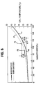
- the voltage and cell temperature characteristics take the form as illustrated in Figures 5 and 6.
- the battery voltage increases slowly for 90% of the battery capacity during charging, but starts to climb steeply after that from point P1 in Figure 5.
- the voltage then levels off at point P3 and, for a NICD battery, then starts to decline from point P3 to point P4. This is shown by curve b in Figure 5.
- the voltage tends to flatten out, from points P3 to P5 in curve a of Figure 5.
- Figure 6 illustrates the temperature curve.
- the temperature increases gradually for 90% of the capacity (with a steeper increase for the NIMH battery) and increases more steeply near to the point of full charge, points P6 to P7 in curve c representing a NICD battery and points P8 to P9 in curve d representing a NIMH battery.
- US Patent No. 5,206,579 discloses a battery charging scheme in which a maximum peak holding means is used to detect the end-of-charge of a nickel-cadmium battery.
- WO-A-92 11680 discloses a battery charging scheme which is able to charge different kinds of batteries.
- each battery incorporates an electrical element which is coupled to one of the terminals.
- the electrical element which in the described embodiment is in the form of a resistor, indicates to the battery charge the type of battery and the battery capacity of the inserted battery.
- the battery charge uses the information derived from the electronic component present in the battery to determine the appropriate charging algorithm. Thus before charging takes place, the type of battery and the capacity thereof has to be determined. This determination is made on the basis of the information provided by specially modified batteries.
- NIMH batteries For NIMH batteries, if only dT/dt is used, they are normally not provided with a full charge (100%). Consequently, a lower current trickle charge which may require to be supplied for three or four hours, needs to be provided in order to ensure full charge.
- the invention seeks to provide a versatile battery charger which can be used for both NICD and NIMH batteries.
- a battery charging circuit including:
- the present invention enables a battery charger to be constructed which can be used for both NICD and NIMH batteries without the need to identify the type of battery being charged.
- the enabling means includes a circuit for measuring the rate of change of temperature of a battery cell to be charged with respect to time (a dT/dt circuit).
- the enabling means can also include a circuit for measuring the rate of change of a cell voltage with respect to time (a dV/dt circuit).
- an appropriate one of the dV/dt and dT/dt circuits can be selected for carrying out pre-measurements prior to the actual measurements for charge termination.
- the selection between the dV/dt circuit and the dT/dt circuits can be made responsive to a thermistor included in the battery pack.
- the pre measurement using the dV/dt or dT/dt circuit is particularly useful in avoiding false detection due to noise.
- the detection concepts include universal end-of-charge detection when charging NICD and/or NIMH batteries without the need to indicate which kind of battery is being used by the user; simple, low cost but accurate way of implementing negative delta-V detection (with which the present invention is principally concerned); and a whole series of charge termination techniques to ensure fast but safe battery charging.
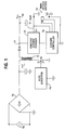
- Figure 1 illustrates a battery charger controller Y3 in use with an ac/dc converter Y1, a constant current charger circuit Y2 and a NICD or NIMH battery pack Y4 to realise a basic fast (one hour or less) battery charger.
- the ac/dc converter Y1 is connected via a switching element in the form of a transistor Y6 to the primary side of a transformer Y17.
- the primary side of the transformer Y17 is connected to the output of a bridge rectifier Y5 across which is connected an ac power supply Y8 having a range of between 90 to 270V.
- the ac/dc converter Y1 converts AC power from the supply Y8 to DC power on line Y7 on the secondary side of the transformer Y17 through the bridge rectifier Y5 and the switching element Y6.
- Power line Y7 in addition to supplying power to a portable computer through an auxiliary output AO, also supplies power for battery charging through the constant current charger circuit Y2.
- the constant current charger circuit is a power converter which provides a constant current through its output Qc to charge the battery pack Y4.
- a relatively constant current is needed for charging the battery if a voltage drop (-dV) method of end-of-charge detection is to be used, as any variation in the voltage level during charging must then be due to the capacity of the battery.
- Reference Y9 denotes a thermistor which can be supplied with the battery pack Y4 for reasons explained hereinafter.
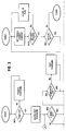
- FIG. 2 illustrates the composition of the battery charger controller Y3 (within the dotted boundary).
- the thick black lines denote an 8 bit bus and the thin line denotes a single bit line.
- Inputs for the charger controller Y3 include a voltage on the auxiliary output AO (terminal AUX), the battery voltage (terminal V batt ), a cell temperature signal (terminal Temp) and a power-on signal (terminal Power-on).
- Outputs from the charger controller Y3 are supplied by drivers M20,M21 and M22 to implement ultra-fast charging, fast charging or trickle charging respectively at the external charger circuit Y2.
- a power sharing detector M2 Upon power-up, a power sharing detector M2 implements ultra-fast charging. This is done by appropriate signals from the Q and Q outputs 2,4 of the power sharing detector M2, through gates M18 and M19, which control the drivers M20 and M21.
- the gate M18 has one input connected to the Q output 2 of the power sharing detector M2 and its other input connected to the Q output 22 of a flip-flop M17 which will be described later.
- the gate M19 has one input connected to the Q output 4 of the power sharing detector M2 and its other input connected to the Q output 22 of the flip-flop M17. If the computer is off, charging will be in the ultra-fast mode. Actual implementation of the charging rate is by the external charger circuit Y2, controlled by the drivers M20,M21 and M22.
- the cell temperature read from thermistor Y9 ( Figure 1), is supplied to the Temp terminal, and fed through an ADC channel plus filter M4 into a thermistor detector circuit M6.
- a dT/dt detector M7 is enabled by the Q output 6 of the thermistor detector M6. If a thermistor is not used, a dV/dt detector M5 is enabled by the Q output 8 of the thermistor detector M6.
- the rate of change of the cell temperature is measured. If this rate exceeds a certain limit, a dT/dt flag will be set, indicating a fast rising cell temperature, which is normally the case just before the end-of-charge of the battery. The setting of the dT/dt flag will be indicated by a "high" level at the Q output 10 of the dT/dt detector of the block M7.
- the rate of change of the battery voltage is measured. If it is found to be rising at or above a predetermined rate, a dV/dt flag will be set. This is also an indication that end of charge is approaching as normally, near to the end-of-charge point (90% capacity point), the battery voltage rises steeply before levelling off at its peak and later dips (in the case of an NICD battery) or flattens out (in the case of an NIMH battery).
- both a -dV detector M9 and a zero dV/dt detector M10 will be enabled by the Q outputs 12,10 from the dV/dt and dT/dt detectors M5 and M7 through a gate M8.
- the -dV detector M9 any voltage drop after the setting of the dT/dt or dV/dt flag will be detected and verified. Confirmation of a true voltage drop detection will be indicated by setting a -dV flag putting a "high" level at the Q output 14 of the -dV detector M9. Detailed explanation of the -dV detector follows later.
- the zero dV/dt detector M10 measures the slope of the battery voltage until a flat slope is detected within a certain time frame. This flat slope indicates that the peak voltage of the battery has been reached and can be used as an end-of-charge indication, particularly for an NIMH battery which may not exhibit any pronounced voltage dip in its fully charged state. Its Q output 16 is set high in this state.
- both NICD and NIMH batteries can be charged by the same system without the need to tell the system which kind of battery is being used.
- circuits M3,M4,M5,M6,M7,M8,M9 and M10 constitute a battery charger monitor BCM which is described in more detail with reference to Figure 4.
- the flip-flop M17 can also be set by other circuits besides M9 and M10, as described in the following.
- a battery presence detector M15 connected to sample the battery voltage at terminal V batt through an ADC channel and filter M3, can determine whether a battery is present at the V batt terminal or not. This is because the Qc output 1 of the constant current charger Y2 in Figure 1 assumes a preset voltage value when the battery Y4 is not connected, which is distinctively higher than the maximum voltage that the battery can go in its fully charged state. Thus if the battery presence detector M15 detects a value nearer to the preset output level of the constant current charger Y2 it will interpret that the battery is not present and set the flip-flop M17 through the gate M16, by having a "high" level at its Q output 24.
- the battery presence detector M15 will detect its presence and reset its Q output 24 to a "low” level. This negative going transition will trigger a reset circuit M26 to reset all detectors in the battery charger controller Y3 by a signal RAD at its output for a fresh detection cycle. This enables new packs of batteries to be charged upon replacement without the need for power reset.
- the flip-flop M17 is normally reset to enable ultra-fast or fast charging, enabling drivers M20 and M21 and disabling driver M22 upon power-up, provided the ambient temperature in the battery pack Y4 before the start of charging falls within a temperature window.
- This temperature window is set by a range defined by a lowest and highest value, for example, 0°C and 40°C respectively. The reason is that if the ambient temperature around the battery pack Y4 is outside this range, it is not advisable to have ultra-fast or fast charging of the battery due to charge efficiency and safety reasons.
- This ambient temperature comparison is done by an ambient temperature detector M24 receiving the temperature range Rt at its input 28. The detector M24 is enabled on power-up by a signal at its enable input 30.
- the detector M24 will output on its Q output 32 a "high" signal to a set pin 34 of the flip-flop M17. After this the Q and Q outputs 20,22 of M17 will be determined by the states of any one of eight detection circuits M9,M10,M11,M13,M14,M15,M25 or M28, that is a "high” signal from the outputs of any one of these circuits will inhibit ultra-fast or fast charging and enable trickle charging.
- M11 denotes a maximum temperature detector which samples the digital form of the cell temperature during charging from the Temp input via the ADC channel and filter M4.
- the maximum temperature detector M11 will set a Temp flag at its Q output 38 if its input exceeds a certain maximum value Tmax set internally.
- This maximum value Tmax could be in the range of 50 to 60°C. Above this temperature (by 1°C or more) it is not advisable to charge the battery using a high current due to charge efficiency and safety reasons.
- the setting of the Temp flag on line 38 will set the flip-flop M17 thereby switching the charging rate to the trickle mode.
- the rate of change of the battery voltage at terminal V batt is monitored by a full cell detector circuit M25. Since for an already charged battery its voltage rises rapidly for the first few minutes of recharging, this occurrence can be detected by the circuit M25 to indicate a "full" battery. Thus a "high" signal is generated at its Q output 40 which sets the flip-flop M17 via the gate M16.
- the time frame used to set the initial period for this "full" cell detection is generated by a one-shot timer M12 which is triggered by the Power-on signal from the Power-on terminal.
- a maximum voltage detector M28 which measures the battery voltage during the initial few minutes of the charging cycle and cuts off charging if its value exceeds a maximum voltage reference V max , as the battery is most likely a "full" one. This is done by its Q output 44 going high and being supplied to the gate M16 via a gate M29. The time frame used for this detection is also taken from the one-shot timer M12, connected to the enable input 42 of the maximum voltage detector M28. By detecting fully charged batteries during the initial portion of the charge cycle by detectors M25 and M28, unnecessary charging can be avoided and also the battery is better protected against overcharging.
- a faulty cell detector M13 also operates. After this preset time frame during which ultra-fast or fast charging is in progress, the detector M13 will measure the battery voltage and if it is below a certain minimum level V min , its Q output 46 goes "high" and the flip-flip M17 is set.
- a count-down timer M14 which starts counting down after receiving the power-on signal at its input 48 and sets the flip-flop M17 via its Q output 50 through gate M16 when its content is decremented to zero. Both this timer M14 and the maximum temperature detector M11 are important to terminate charging in cases when the main detection methods (dV/dt M5, dT/dt M7, -dV M9 and zero dV/dt M10) fail, so as to ensure the survival of the battery pack at the high charging current.
- M27 denotes a clock circuit which generates clock signals for each charging cycle. All readings are taken once every charge cycle.
- Figure 3 is the flow chart of the operation inside the described battery charger circuit.
- the cell temperature is measured in the ambient temperature detector circuit M24. If it falls outside the temperature window Rt (0°C to 40°C, as mentioned before) trickle charging M22 will take place until it falls back to within range. If cell temperature is within range, ultra-fast charging M20 will be done.
- the battery voltage is measured by circuit M28. If it exceeds a certain level per cell, this indicates that the battery is already fully charged so that high current charging is unnecessary. Ultra-fast charging will be terminated and replaced with a trickle charge (in the "burst" mode). In addition the rate of change of battery voltage is also monitored by full cell detector M25 within the same time frame. If a certain threshold is exceeded, indicating also a "full” cell condition, ultra-fast charging is stopped, and the trickle charge "burst" mode is entered.
- the battery level is also checked during the same period by M13 for faulty conditions. If the battery is found to be faulty, ultra-fast charging is stopped, and the trickle charge "burst" mode is entered. After the first few minutes determined by the one-shot timer M12, no checking will be done for maximum voltage level, faulty voltage level and "full" cell detection.
- the battery is then checked for the inclusion of a thermistor Y9 at block M6. If a thermistor is used, dT/dt (rate of change of cell temperature) is measured at block M7. If a thermistor is not used, dV/dt (rate of change of battery voltage) is measured at block M5. At these two blocks the dT/dt or the dV/dt is monitored for the pre-measurement phase and the respective flags set accordingly when detection occurs.
- dT/dt rate of change of cell temperature
- dV/dt rate of change of battery voltage
- the setting of either the dT/dt or dV/dt flag completes the pre-measurement phase and opens the gate for the final end-of-charge detection at M9 (for detection of setting of -dV flag) and M10 (for detection of the setting of the zero dV/dt flag) concurrently.
- Setting of either the -dV flag or zero dV/dt flag will complete the end-of-charge detection, after which charging will be replaced with the "burst" mode (trickle charge).
- a scan time follows during which the battery presence detection (by M15), cell temperature detection (by M11) and charging time detection (by M14) are done. If the battery is removed, charging is stopped and the "burst" mode (trickle charging) takes over. In the "burst” mode, the battery contacts are continuously scanned and if a battery is reconnected, the whole charge cycle is repeated.
- the trickle charge current is set, M22.
- the battery presence detector M15 detects if a "full” battery is removed and replaced with another pack. In that event, charging will restart from the beginning without the need for any power down and up again procedure. Otherwise, once in the "burst” mode, the charge cycle will remain in that mode until the power-on reset is applied again.
- FIG 4 is a block diagram of a battery charger monitor BCM.
- the battery charger monitor BCM comprises the ADC channel and filter M3 connected to the battery voltage input terminal V batt , the ADC channel and filter M4 connected to the cell temperature input Temp, the dV/dt detector M5, the thermistor detector M6, the dT/dt detector M7, the gate M8, a further gate B4, the -dV detector M9 and the zero dV/dt detector M10.
- the gate M16 is shown in Figure 4, but only two of its inputs are illustrated.
- the gate M16 is shown connected to the flip-flop M17.
- Figure 4 also shows a timer B11 which receives a clock signal Clock from the clock M27 in Figure 2 and produces outputs Tclk and Vclk.
- a timer B11 which receives a clock signal Clock from the clock M27 in Figure 2 and produces outputs Tclk and Vclk.
- the battery voltage is measured at the V batt terminal and converted from its analog form to a digital form by one channel of the analog-to-digital converter B1.
- the digital value is then fed into the simple digital filter B2 for filtering, through an 8-bit bus 60.
- the cell temperature is measured through the Temp terminal and fed into another channel of the analog-to-digital converter B7 and filtered by the digital filter B8.
- the thermistor detector M6 samples the 8-bit information from the filter B8 and determines whether a thermistor Y9 is being used or not. If yes, the dT/dt detector, M7, will be enabled and the dV/dt detector, M5, disabled. If otherwise, M5 will be enabled and M7 disabled.
- the dV/dt detector M5 If the dV/dt detector M5 is enabled, it will monitor the gradient (dV/dt) of the voltage charging curve which is as illustrated in Figure 5. As can be seen in Figure 5, there is a substantial increase in the gradient between points P1 and P2 and this causes a dV/dt flag to be set. If the dT/dt detector M7 is enabled it will similarly monitor the gradient (dT/dt) of the temperature curve as illustrated in Figure 6 until it detects a sharp increase in gradient, between points P6 and P7 on curve c for a NICD battery or points P8 and P9 on curve d for a NIMH battery when it will set a dT/dt flag.
- the gradient is monitored by making sequential measurements of voltage or temperature at interval durations (e.g. between points P1 and P2 in Figure 5) generated by the timer B11.
- T clk sets the interval duration for dT/dt measurements and V clk sets the interval duration for dV/dt measurements.
- the -dV detector M9 and the zero dV/dt detector M10 are simultaneously activated, through the gate M8, enabling -dV (voltage drop) and zero dV/dt (voltage level) measurements to be taken concurrently.
- battery voltage measurements (through the 8-bit bus from the filter B2) are taken by the -dV detector M9 at one second intervals to monitor any negative voltage drop.
- a -dV flag is set. This indicates an end-of-charge condition in an NICD battery.
- Z clk is a clock signal derived from the gate B4, the inputs of which come from the dV/dt detector M5 (V clk ) or the dT/dt detector M7 (T clk ) depending on which of these circuits is enabled for pre-measurements.
- the set pin 34 of the flip-flop M17 will be held “low” and the clear pin 35 held “high” (always) to disable ultra-fast or fast charging ("low” at the Q output 22 and “high” at the Q output 20) no matter what signal is available at the D input 18.
- the enable signal (a "high” level) arrives at the set pin 34, the high current charging (ultra-fast or fast mode) is activated (“high” at the Q output and "low” at the Q output) until detection is made by the -dV detector M9 or the zero dV/dt detector M10, after which trickle charging will take over.
- Figure 7 is a circuit diagram for the negative (-dV) detector M9.
- the battery voltage at terminal V batt is fed into the analog-to-digital converter (ADC) B1.
- ADC analog-to-digital converter
- the battery voltage is converted from an analog form into a digital form and fed into the digital filter B2.
- the 8-bit information is then stored in a V aver register B3.
- a plurality of registers B5,B6,B17 are connected to sequentially receive filtered voltage values.
- the V aver register B3 is connected to a V max register B5, which is connected to V aver1 register B6 which is connected to V aver2 register B17.
- All the registers B3,B5,B6 and B17 are clocked by a signal clk from a timer B18 which takes its input from clock M27 in Figure 2.
- the signal clk has the same frequency as the measurement cycle (the frequency at which battery voltage measurements are taken).
- On the first clock pulse data in the register B3 is shifted into B5, with the latest battery voltage data being stored in B3.
- the data On the next cycle, the data is clocked through so that the contents of B5 are shifted into B6, the contents of B3 into B5, etc.
- V aver (B3), V max (B5), V aver1 (36) and V aver2 (B17) should have data in them.
- V max register B5 is a peak voltage detector which continuously compares the data from register B3 at input 50 with that from register B5 at input 52. While input 50 is greater than or equal to input 52 an enable signal is fed to register B5 so that the higher value (content of register B3) will be loaded into register B5 at the next clock cycle. Otherwise, the enable signal from peak detector B14 will not be active and the content of register B5 will not be changed at the next cycle. Thus the V max register B5 always contains the highest voltage level on record among all the registers.
- a -dV detector B9 compares the contents of register B3, which is the newest being read in, with that from register B5 which holds the highest value. Once the content in register B3 is lower than that in register B5 by a predetermined value (e.g. 50mV) and is detected by -dV detector B9, its Q output 56 will go "high".
- a predetermined value e.g. 50mV
- Registers B6 and B17 contain the previous voltage data prior to the detection of the voltage drop. Their data is fed together with that from register B5 into a level detector B10. Only when all three data inputs are equal will the Q output 58 of level detector B10 go "high".
- This system can be used for re-validation of any possible -dV detection, the number of times depending on the number of outputs that the shift register can offer. Only when all Q pins of shift register B12 are "high” will output circuit B13 confirm the validity of the detection. It will output a "high” signal at output 62 to disable ultra-fast or fast charging at the external charger circuit Y2.
- the register B5 will be enabled regardless of the state of the peak detector B14. Therefore the contents of the register B3 will be clocked into the register B5, the false data in the register B5 will be clocked into the register B6, and the data in the register B6 will be clocked into the register B17.
- the next clock pulse or cycle will result in another false detection, as the false data is now in register B6, and result in the false data being clocked into register B17.
- a further false detection will occur but the false data will be erased from register B17 and the circuit of Figure 7 can resume further measurement.
- All readings in storage are updated during every battery voltage measurement in an ongoing process no matter whether there is any -dV detection or not. All measurements and re-checking are done without any interruption to charging and within a very short time frame (a few seconds) thus giving very quick response to the monitoring and avoiding overcharging, without any compromise to the accuracy. Also minimum filtering is needed, thus saving cost.
- the -dV detection circuit described above with reference to Figure 7 employs a detection method that makes use of the fact that the battery voltage changes very gradually, unlike switching noises which are in the range of hundreds of kHz. By maintaining measurements before the moment when -dV is suspected to occur, and also taking measurements after that moment, it is possible to filter out the switching noises and only act on genuine drops in voltage.
- the reading at V1 is compared to that at V2. If amplitudes at V1 and V2 are not the same, then the detection is rejected as noise, as the voltages at V1 and V2 are not expected to differ due to the short time duration between measurements (typically one second interval).
- the threshold e.g. 50mV
Claims (12)
- Circuit de charge de batterie comprenant :un circuit de détection de chute de tension (M9) pour produire un premier signal de détection (14) lors de la détection d'une chute de tension de cellule en fonction du temps ;un circuit de détection de tension crête (M10) pour produire un deuxième signal de détection (16) lors de la détection d'une période à tension de cellule constante en fonction du temps ;un moyen de validation (M5, M7) pour permettre auxdits circuits de détection (M9, M10) de fonctionner simultanément et pour permettre aux deux circuits de détection (M9, M10) d'être sensibles à la tension de batterie (Vbatt) d'une batterie (Y4) à charger ; etdes moyens de charge de batterie (V2) connectés pour recevoir lesdits premier (14) et deuxième (16) signaux de détection, lesdits moyens de charge de batterie étant disposés pour charger la batterie jusqu'à ce que l'un desdits premier (14) et deuxième (16) signaux de détection soit généré.
- Circuit de charge de batterie selon la revendication 1, dans lequel le moyen de validation comprend un circuit (M5) pour mesurer la vitesse de changement de la tension de batterie (Vbatt) en fonction du temps.
- Circuit de charge de batterie selon la revendication 1 ou 2, dans lequel le moyen de validation comprend un circuit (M7) pour mesurer la vitesse de changement en fonction du temps de la température de la batterie (Y4) à charger.
- Circuit de charge de batterie selon la revendication 3 prise dans sa dépendance de la revendication 2, qui comprend un circuit de détection de thermistance (M6) permettant de détecter si une thermistance est présente ou non au niveau de la batterie (Y4) à charger et pour sélectionner le circuit (M7) pour mesurer la vitesse de changement de température si une thermistance est détectée, et pour sélectionner le circuit (M5) pour mesurer la vitesse de changement de tension de cellule si une thermistance n'est pas détectée.
- Circuit de charge de batterie selon l'une quelconque des revendications précédentes, comprenant un détecteur de température ambiante (M24) pour déterminer si la température ambiante se trouve ou non dans une plage de température prédéterminée (Rt) et pour sélectionner un courant de charge en conséquence.
- Circuit de charge de batterie selon l'une quelconque des revendications précédentes, comprenant un circuit de détection de température maximale (M11) permettant de détecter la température de la batterie et de réduire la vitesse de charge lorsqu'une température maximale (Tmax) est dépassée.
- Circuit de charge de batterie selon l'une quelconque des revendications précédentes, comprenant un circuit de détection de batterie pleine (M25) permettant de détecter l'augmentation de la tension de batterie (Vbatt) au début de la charge par lesdits moyens de charge de batterie et de sélectionner le courant de charge en conséquence.
- Circuit de charge de batterie selon l'une quelconque des revendications précédentes, comprenant un circuit de détection de tension maximale (M28) pour détecter la tension de batterie (Vbatt) lors du début de la charge et pour commander le courant de charge si la tension détectée dépasse un maximum prédéterminé (Vmax).
- Circuit de charge de batterie selon la revendication 7 ou 8, dans lequel une période de détection de batterie pleine et de tension maximale, après le début de la charge par les moyens de charge de batterie, est déterminée par un circuit de temporisation.
- Circuit de charge de batterie selon l'une quelconque des revendications précédentes, qui présente plusieurs sorties de charge pour effectuer respectivement une charge ultra-rapide, une charge rapide et une charge à régime lent.
- Circuit de charge de batterie selon la revendication 10, dans lequel ladite vitesse prédéterminée est soit celle de charge ultra-rapide soit celle de charge rapide.
- Circuit de charge de batterie selon l'une quelconque des revendications précédentes comprenant un circuit de temporisation (M14) pour déterminer un temps maximum de charge.
Applications Claiming Priority (4)
| Application Number | Priority Date | Filing Date | Title |
|---|---|---|---|
| GB9309175 | 1993-05-05 | ||
| GB939309175A GB9309175D0 (en) | 1993-05-05 | 1993-05-05 | A single end-charge detection method for both nicd and nimh batteries |
| GB939309177A GB9309177D0 (en) | 1993-05-05 | 1993-05-05 | An innovative and versatile battery charger controller design employing state of the art detection concepts for applications in charging batteries |
| GB9309177 | 1993-05-05 |
Publications (2)
| Publication Number | Publication Date |
|---|---|
| EP0623986A1 EP0623986A1 (fr) | 1994-11-09 |
| EP0623986B1 true EP0623986B1 (fr) | 1998-04-29 |
Family
ID=26302852
Family Applications (1)
| Application Number | Title | Priority Date | Filing Date |
|---|---|---|---|
| EP94300655A Expired - Lifetime EP0623986B1 (fr) | 1993-05-05 | 1994-01-28 | Chargeur de batterie |
Country Status (3)
| Country | Link |
|---|---|
| US (1) | US5489836A (fr) |
| EP (1) | EP0623986B1 (fr) |
| DE (1) | DE69409863T2 (fr) |
Families Citing this family (37)
| Publication number | Priority date | Publication date | Assignee | Title |
|---|---|---|---|---|
| EP0623985B1 (fr) * | 1993-05-05 | 1998-07-29 | Sgs-Thomson Microelectronics Pte Ltd. | Détecteur de répartition de la puissance |
| US5596260A (en) * | 1994-05-13 | 1997-01-21 | Apple Computer, Inc. | Apparatus and method for determining a charge of a battery |
| FI99176C (fi) * | 1994-11-11 | 1997-10-10 | Nokia Mobile Phones Ltd | Menetelmä erityyppisten akkujen nopeata lataamista varten |
| US5686808A (en) * | 1995-05-31 | 1997-11-11 | Lutz; Frank T. | Universal battery charger and method |
| KR970024434A (ko) * | 1995-10-12 | 1997-05-30 | 김광호 | 겸용 배터리 충전기와 그 제어 방법 |
| US5744933A (en) * | 1995-11-13 | 1998-04-28 | Kn Technos Co., Ltd. | Vending machine for charging a secondary battery of a mobile phone |
| AU715250B2 (en) * | 1995-11-13 | 2000-01-20 | Marukan Kabushiki Kaisha | Vending machine for charging a secondary battery of a mobile phone |
| KR0151495B1 (ko) * | 1995-12-02 | 1998-12-15 | 김광호 | 배터리 충전 모드 제어 회로 |
| US6495992B1 (en) * | 1996-03-26 | 2002-12-17 | Norvik Traction Inc. | Method and apparatus for charging batteries utilizing heterogeneous reaction kinetics |
| US5729116A (en) * | 1996-12-20 | 1998-03-17 | Total Battery Management, Inc. | Shunt recognition in lithium batteries |
| US6040685A (en) * | 1996-08-16 | 2000-03-21 | Total Battery Management, Inc. | Energy transfer and equalization in rechargeable lithium batteries |
| US5900718A (en) * | 1996-08-16 | 1999-05-04 | Total Battery Management, | Battery charger and method of charging batteries |
| US6037747A (en) * | 1997-10-15 | 2000-03-14 | Lucent Technologies Inc. | Mode selection circuit for a battery and method of operation thereof |
| US6043631A (en) * | 1998-01-02 | 2000-03-28 | Total Battery Management, Inc. | Battery charger and method of charging rechargeable batteries |
| JP3378189B2 (ja) * | 1998-02-28 | 2003-02-17 | 株式会社マキタ | 充電装置及び充電方法 |
| US6137263A (en) * | 1998-04-03 | 2000-10-24 | Nippon Soken, Inc. | Method and device for checking battery charge |
| US6018227A (en) * | 1998-06-22 | 2000-01-25 | Stryker Corporation | Battery charger especially useful with sterilizable, rechargeable battery packs |
| US6222343B1 (en) | 1998-08-14 | 2001-04-24 | Milwaukee Electric Tool Corporation | Battery charger, a method for charging a battery, and a software program for operating the battery charger |
| US7336054B2 (en) * | 1998-08-14 | 2008-02-26 | Milwaukee Electric Tool Corporation | Apparatus and method of activating a microcontroller |
| US6326767B1 (en) | 1999-03-30 | 2001-12-04 | Shoot The Moon Products Ii, Llc | Rechargeable battery pack charging system with redundant safety systems |
| US6184655B1 (en) | 1999-12-10 | 2001-02-06 | Stryker Corporation | Battery charging system with internal power manager |
| JP2001186683A (ja) | 1999-12-27 | 2001-07-06 | Sanyo Electric Co Ltd | 電池の急速充電方法 |
| US6348777B1 (en) | 2000-02-29 | 2002-02-19 | Alaris Medical Systems, Inc. | Power management system |
| JP2002165380A (ja) * | 2000-11-24 | 2002-06-07 | Tokyo R & D Co Ltd | 組電池の充電システム |
| FR2852459B1 (fr) * | 2003-03-11 | 2007-03-02 | Lionel Coq | Procede et dispositif de recharge de systemes electroniques portables |
| SE525604E5 (sv) * | 2003-04-30 | 2013-10-22 | Ctek Sweden Ab | Metod för laddning av ett batteri, datorläsbart medium samt batteriladdare |
| US20060113956A1 (en) * | 2003-05-07 | 2006-06-01 | Bublitz Scott D | Battery charger and assembly |
| CN100361370C (zh) * | 2005-07-11 | 2008-01-09 | 李建国 | 自适应跟踪式动力电池多阶段高速充电系统及其充电方法 |
| KR100761754B1 (ko) * | 2006-02-01 | 2007-09-28 | 삼성전자주식회사 | 배터리 유무를 검출하는 방법 및 장치 |
| US20080174263A1 (en) * | 2007-01-22 | 2008-07-24 | Snap-On Incorporated | Battery charger for different capacity cells |
| US7843167B2 (en) * | 2007-01-22 | 2010-11-30 | Snap-on Incorporated, Inc. | Battery charger with charge indicator |
| DE102007051052A1 (de) * | 2007-10-16 | 2009-04-23 | C. & E. Fein Gmbh | Verfahren zum Laden von wiederaufladbaren Lithium-Akkumulatoren, Ladegerät und Lithium-Akkumulator |
| US9461341B2 (en) | 2012-12-26 | 2016-10-04 | Semiconductor Energy Laboratory Co., Ltd. | Power storage device and method for charging the same |
| US9882407B2 (en) * | 2014-09-05 | 2018-01-30 | Apple Inc. | Battery detection via voltage regulation of battery terminals |
| US9859531B2 (en) | 2015-02-06 | 2018-01-02 | Ovonic Battery Company, Inc. | Alkaline and non-aqueous proton-conducting pouch-cell batteries |
| WO2019037115A1 (fr) * | 2017-08-25 | 2019-02-28 | 深圳市云中飞网络科技有限公司 | Dispositif terminal et procédé de surveillance de sécurité de batterie ainsi que système de surveillance associés |
| EP3584874A1 (fr) | 2018-06-19 | 2019-12-25 | Siemens Aktiengesellschaft | Unité de stockage de l'énergie électrique, procédé de surveillance d'une telle unité de stockage ainsi que véhicule |
Family Cites Families (11)
| Publication number | Priority date | Publication date | Assignee | Title |
|---|---|---|---|---|
| US4388582A (en) * | 1978-05-31 | 1983-06-14 | Black & Decker Inc. | Apparatus and method for charging batteries |
| US4670703A (en) * | 1985-05-06 | 1987-06-02 | General Electric Company | Battery charger with three different charging rates |
| CA1335601C (fr) * | 1988-01-29 | 1995-05-16 | Nec Corporation | Circuit de controle de la charge pour systeme de telephone sans fil |
| US5206579A (en) * | 1990-02-26 | 1993-04-27 | Nippon Densan Corporation | Battery charger and charge controller therefor |
| US5200690A (en) * | 1990-10-01 | 1993-04-06 | Sanyo Electric Co., Ltd. | Quick charge control apparatus and control method thereof |
| JPH0813169B2 (ja) * | 1990-12-01 | 1996-02-07 | 三洋電機株式会社 | 充電装置及び充電方法 |
| WO1992011680A1 (fr) * | 1990-12-17 | 1992-07-09 | Motorola, Inc. | Plan et appareil de detection des caracteristiques d'une batterie |
| JP3003243B2 (ja) * | 1991-03-18 | 2000-01-24 | ソニー株式会社 | バッテリー |
| US5166596A (en) * | 1991-08-29 | 1992-11-24 | Motorola, Inc. | Battery charger having variable-magnitude charging current source |
| US5200686A (en) * | 1991-10-10 | 1993-04-06 | Motorola, Inc. | Method and apparatus for determining battery type |
| JP3048755B2 (ja) * | 1992-07-10 | 2000-06-05 | 三洋電機株式会社 | 2次電池の充電装置 |
-
1994
- 1994-01-28 EP EP94300655A patent/EP0623986B1/fr not_active Expired - Lifetime
- 1994-01-28 DE DE69409863T patent/DE69409863T2/de not_active Expired - Fee Related
- 1994-02-03 US US08/190,944 patent/US5489836A/en not_active Expired - Fee Related
Also Published As
| Publication number | Publication date |
|---|---|
| DE69409863T2 (de) | 1998-10-08 |
| DE69409863D1 (de) | 1998-06-04 |
| US5489836A (en) | 1996-02-06 |
| EP0623986A1 (fr) | 1994-11-09 |
Similar Documents
| Publication | Publication Date | Title |
|---|---|---|
| EP0623986B1 (fr) | Chargeur de batterie | |
| EP0623987B1 (fr) | Chargeur de batterie | |
| US6366056B1 (en) | Battery charger for lithium based batteries | |
| US5864220A (en) | Method and apparatus for controlling the charging of a rechargeable battery to ensure that full charge is achieved without damaging the battery | |
| US5808447A (en) | Pulse charging method for rechargeable batteries | |
| EP0972328B1 (fr) | Procede et appareil pour charger des batteries par cinetique de reactions heterogenes | |
| US5583417A (en) | Power sharing detector for use with a battery charger and an auxiliary device | |
| US5686815A (en) | Method and apparatus for controlling the charging of a rechargeable battery to ensure that full charge is achieved without damaging the battery | |
| US4302714A (en) | Rechargeable battery charger system for charging testing, rejuvenation and preventative maintenance | |
| EP0771487B1 (fr) | Mode et appareil de traitement des batteries | |
| US20010000212A1 (en) | Battery system providing indicia of a charging parameter | |
| IE61854B1 (en) | Method and apparatus for determining battery type and modifying operating characteristics | |
| JPH08140270A (ja) | 二次電池のパラメータ測定方法ならびにそれを用いた二次電池の充放電制御方法および寿命予測方法、ならびに、二次電池の充放電制御装置およびそれを用いた電力貯蔵装置 | |
| JPH11509078A (ja) | バッテリ充電処理の制御および終了 | |
| US5617005A (en) | Method and apparatus for charging lead acid batteries | |
| Gonzalez et al. | Considerations to improve the practical design of universal and full-effective NiCd/NiMH battery fast-chargers | |
| Gonzalez et al. | Ni-Cd and Ni-MH battery optimized fast-charge method for portable telecommunication applications | |
| JP2756231B2 (ja) | 電池充電回路 | |
| JP2754506B2 (ja) | セルショート検出充電装置 | |
| JPH10322917A (ja) | 二次電池の劣化判定方法およびその装置 | |
| JP3101117B2 (ja) | 二次電池の充電方法 | |
| JP3499902B2 (ja) | 二次電池充電装置 | |
| JPH08149709A (ja) | 二次電池の充電装置 | |
| JP3426616B2 (ja) | 電池の充電装置 | |
| JP3555989B2 (ja) | 二次電池の充電方法 |
Legal Events
| Date | Code | Title | Description |
|---|---|---|---|
| PUAI | Public reference made under article 153(3) epc to a published international application that has entered the european phase |
Free format text: ORIGINAL CODE: 0009012 |
|
| AK | Designated contracting states |
Kind code of ref document: A1 Designated state(s): DE FR GB IT |
|
| 17P | Request for examination filed |
Effective date: 19950505 |
|
| 17Q | First examination report despatched |
Effective date: 19960816 |
|
| GRAG | Despatch of communication of intention to grant |
Free format text: ORIGINAL CODE: EPIDOS AGRA |
|
| GRAG | Despatch of communication of intention to grant |
Free format text: ORIGINAL CODE: EPIDOS AGRA |
|
| GRAH | Despatch of communication of intention to grant a patent |
Free format text: ORIGINAL CODE: EPIDOS IGRA |
|
| GRAH | Despatch of communication of intention to grant a patent |
Free format text: ORIGINAL CODE: EPIDOS IGRA |
|
| GRAA | (expected) grant |
Free format text: ORIGINAL CODE: 0009210 |
|
| AK | Designated contracting states |
Kind code of ref document: B1 Designated state(s): DE FR GB IT |
|
| REF | Corresponds to: |
Ref document number: 69409863 Country of ref document: DE Date of ref document: 19980604 |
|
| ITF | It: translation for a ep patent filed |
Owner name: PORTA CHECCACCI E BOTTI S.R.L. |
|
| ET | Fr: translation filed | ||
| PLBE | No opposition filed within time limit |
Free format text: ORIGINAL CODE: 0009261 |
|
| STAA | Information on the status of an ep patent application or granted ep patent |
Free format text: STATUS: NO OPPOSITION FILED WITHIN TIME LIMIT |
|
| 26N | No opposition filed | ||
| REG | Reference to a national code |
Ref country code: GB Ref legal event code: IF02 |
|
| PGFP | Annual fee paid to national office [announced via postgrant information from national office to epo] |
Ref country code: DE Payment date: 20040205 Year of fee payment: 11 |
|
| PGFP | Annual fee paid to national office [announced via postgrant information from national office to epo] |
Ref country code: FR Payment date: 20050110 Year of fee payment: 12 |
|
| PGFP | Annual fee paid to national office [announced via postgrant information from national office to epo] |
Ref country code: GB Payment date: 20050126 Year of fee payment: 12 |
|
| PG25 | Lapsed in a contracting state [announced via postgrant information from national office to epo] |
Ref country code: IT Free format text: LAPSE BECAUSE OF NON-PAYMENT OF DUE FEES;WARNING: LAPSES OF ITALIAN PATENTS WITH EFFECTIVE DATE BEFORE 2007 MAY HAVE OCCURRED AT ANY TIME BEFORE 2007. THE CORRECT EFFECTIVE DATE MAY BE DIFFERENT FROM THE ONE RECORDED. Effective date: 20050128 |
|
| PG25 | Lapsed in a contracting state [announced via postgrant information from national office to epo] |
Ref country code: DE Free format text: LAPSE BECAUSE OF NON-PAYMENT OF DUE FEES Effective date: 20050802 |
|
| PG25 | Lapsed in a contracting state [announced via postgrant information from national office to epo] |
Ref country code: GB Free format text: LAPSE BECAUSE OF NON-PAYMENT OF DUE FEES Effective date: 20060128 |
|
| PG25 | Lapsed in a contracting state [announced via postgrant information from national office to epo] |
Ref country code: FR Free format text: LAPSE BECAUSE OF NON-PAYMENT OF DUE FEES Effective date: 20060131 |
|
| GBPC | Gb: european patent ceased through non-payment of renewal fee |
Effective date: 20060128 |
|
| REG | Reference to a national code |
Ref country code: FR Ref legal event code: ST Effective date: 20060929 |