EP0622238B1 - Imprimante à jet d'encre avec motif de référence pour l'alignement de cartouches à jet d'encre multiples - Google Patents
Imprimante à jet d'encre avec motif de référence pour l'alignement de cartouches à jet d'encre multiples Download PDFInfo
- Publication number
- EP0622238B1 EP0622238B1 EP94106212A EP94106212A EP0622238B1 EP 0622238 B1 EP0622238 B1 EP 0622238B1 EP 94106212 A EP94106212 A EP 94106212A EP 94106212 A EP94106212 A EP 94106212A EP 0622238 B1 EP0622238 B1 EP 0622238B1
- Authority
- EP
- European Patent Office
- Prior art keywords
- bars
- pens
- pen
- carriage
- printer
- Prior art date
- Legal status (The legal status is an assumption and is not a legal conclusion. Google has not performed a legal analysis and makes no representation as to the accuracy of the status listed.)
- Expired - Lifetime
Links
Images


Classifications
-
- B—PERFORMING OPERATIONS; TRANSPORTING
- B41—PRINTING; LINING MACHINES; TYPEWRITERS; STAMPS
- B41J—TYPEWRITERS; SELECTIVE PRINTING MECHANISMS, i.e. MECHANISMS PRINTING OTHERWISE THAN FROM A FORME; CORRECTION OF TYPOGRAPHICAL ERRORS
- B41J25/00—Actions or mechanisms not otherwise provided for
- B41J25/34—Bodily-changeable print heads or carriages
-
- B—PERFORMING OPERATIONS; TRANSPORTING
- B41—PRINTING; LINING MACHINES; TYPEWRITERS; STAMPS
- B41J—TYPEWRITERS; SELECTIVE PRINTING MECHANISMS, i.e. MECHANISMS PRINTING OTHERWISE THAN FROM A FORME; CORRECTION OF TYPOGRAPHICAL ERRORS
- B41J2/00—Typewriters or selective printing mechanisms characterised by the printing or marking process for which they are designed
- B41J2/005—Typewriters or selective printing mechanisms characterised by the printing or marking process for which they are designed characterised by bringing liquid or particles selectively into contact with a printing material
- B41J2/01—Ink jet
- B41J2/07—Ink jet characterised by jet control
-
- B—PERFORMING OPERATIONS; TRANSPORTING
- B41—PRINTING; LINING MACHINES; TYPEWRITERS; STAMPS
- B41J—TYPEWRITERS; SELECTIVE PRINTING MECHANISMS, i.e. MECHANISMS PRINTING OTHERWISE THAN FROM A FORME; CORRECTION OF TYPOGRAPHICAL ERRORS
- B41J2/00—Typewriters or selective printing mechanisms characterised by the printing or marking process for which they are designed
- B41J2/005—Typewriters or selective printing mechanisms characterised by the printing or marking process for which they are designed characterised by bringing liquid or particles selectively into contact with a printing material
- B41J2/01—Ink jet
- B41J2/21—Ink jet for multi-colour printing
- B41J2/2132—Print quality control characterised by dot disposition, e.g. for reducing white stripes or banding
- B41J2/2135—Alignment of dots
Definitions
- the present invention relates to printers and plotters. More specifically, the present invention relates to inkjet printers and plotters having multiple pens for multi-color operation.
- Inkjet printer/plotters such as those sold by Hewlett Packard Company, offer substantial improvements in speed over the conventional X-Y plotter.
- Inkjet printer/plotters typically include a pen having an array of nozzles. The pens are mounted on a carriage which is moved across the page in successive swaths.
- Each inkjet pen has heater circuits which, when activated, cause ink to be ejected from associated nozzles. As the pen is positioned over a given location, a jet of ink is ejected from the nozzle to provide a pixel of ink at a desired location.
- the mosaic of pixels thus created provides a desired composite image.
- a typical color inkjet printer/plotter has four inkjet pens, one that stores black ink, and three that store colored inks, e.g., magenta, cyan and yellow. The colors from the three color pens are mixed to obtain any particular color.
- the pens are typically mounted in stalls within an assembly which is mounted on the carriage of the printer/plotter.
- the carriage assembly positions the inkjet pens and typically holds the circuitry required for interface to the heater circuits in the inkjet pens.
- the optical drop detectors detect the position of each ink drop as it leaves the pen.
- the system then calculates the point of impact of the drop on the print media.
- the actual impact point often differs substantially from the calculated impact point due to angularity.
- Angularity results from the movement of the pen in the scan axis as ink is being ejected. That is, there is a delay between the time that the drop of ink is ejected and the time that the drop impacts the media. This flight time delay causes the drop to traverse an angular path toward the media. If not accurately calculated and corrected, this would cause a distortion in the print image.
- this technique has been found to be inadequate for current product specifications for full color printing.
- the first plurality of bars includes a first set of bars printed by each of the pens.
- the first plurality of bars includes a second set of bars printed by one of the pens moving at at least two different horizontal speeds.
- the second plurality of bars includes one column of vertically spaced bars for each of the pens.
- Each column of vertically spaced bars includes a first plurality of vertically spaced bars printed by a first pen.
- a respective column of vertically spaced bars includes a second plurality of vertically spaced bars printed by a respective one of the pens.
- Each column of vertically spaced bars includes a third plurality of vertically spaced bars printed by the first pen.
- the inventive pattern allows for considerable information with respect to pen alignments to be determined by optical scanning.
- Fig. 1 is a perspective view of a thermal inkjet large format printer/plotter incorporating the teachings of the present invention.
- Fig. 2 is a perspective view of the carriage assembly, the carriage positioning mechanism, and the paper positioning mechanism of the inventive printer/plotter.
- Fig. 3 is perspective view of a simplified representation of a media positioning system utilized in the inventive printer.
- Fig. 4 is a right-bottom perspective view of the carriage assembly of the present invention showing the sensor module.
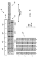
- Fig. 5 is a magnified view of the test pattern utilized to effect pen alignment in accordance with the present teachings.
- Fig. 6a is a right-front perspective view of the sensor module utilized in the system of the present invention.
- Fig. 6b is a right-rear perspective view of the sensor module utilized in the system of the present invention.
- Fig. 6c shows a right-rear perspective view of the sensor module partially disassembled to reveal an outer housing and an inner assembly.
- Fig. 6d is a right-rear perspective view of the inner assembly of the sensor module of the present invention partially disassembled.
- Fig. 6e is a right-rear perspective view of the optical component holder of the sensor module of the present invention disassembled.
- Fig. 7 is a schematic diagram of the optical components of the sensor module of the present invention.
- Fig. 8a is a top view of the phase plate of the sensor module of the present invention.
- Fig. 8b is illustrative of the carriage axis patterns of the test pattern utilized in alignment system of the present invention.
- Fig. 8c is illustrative of the media axis patterns of the test pattern utilized in alignment system of the present invention.
- Fig. 9 shows a frontal representation of first, second, third and fourth inkjet cartridges positioned over media for movement along the carriage scan axis.
- Fig. 10 is a block diagram of the electronic circuit utilized in the alignment system of the present invention.
- Fig. 11 is a graph illustrative of the outputs of the carriage and media position encoders.
- Fig. 12 illustrates the sample pulses generated by the sample pulse generator circuit of the present invention.
- Fig. 13 illustrates the output of the sensor module of the present invention.
- Fig. 14 shows how the output of the sensor module of the present invention appears after amplification and filtering.
- Fig. 15 is a graph which illustrates how the output of the amplification and filtering circuit is sampled to provide data which is input to the slave microprocessor controller of the invention.
- Fig. 16 is a magnified bottom view of the thermal inkjet nozzles of each of the pen cartridges.
- Fig. 17 shows offsets due to speed and the effect of platen curvature for a print image.
- Fig. 18 is a magnified side view of a nozzle above a curved platen.
- Fig. 19 is a graph of print image delay (B) versus carriage speed for the illustrative thermal inkjet printer of the present invention.
- Fig. 1 is a perspective view of a thermal inkjet large format printer/plotter incorporating the teachings of the present invention.
- the printer 10 includes a housing 12 mounted on a stand 14. The housing has left and right drive mechanism enclosures 16 and 18. A control panel 20 is mounted on the right enclosure 18.
- a carriage assembly 100 illustrated in phantom under a transparent cover 22, is adapted for reciprocal motion along a carriage bar 24, also shown in phantom.
- the position of the carriage assembly 100 in a horizontal or carriage scan axis is determined by a carriage positioning mechanism 110 (not shown) with respect to an encoder strip 120 (not shown) as discussed more fully below.
- a print medium 30 such as paper is positioned along a vertical or media axis by a media axis drive mechanism (not shown).
- the media axis is denoted as the 'x' axis and the scan axis is denoted as the 'y' axis.
- Fig. 2 is a perspective view of the carriage assembly 100, the carriage positioning mechanism 110 and the encoder strip 120.
- the carriage positioning mechanism 110 includes a carriage position motor 112 which has a shaft 114 extending therefrom through which the motor drives a small belt 116. Through the small belt 116, the carriage position motor 112 drives an idler 122 via the shaft 118 thereof. In turn, the idler 122 drives a belt 124 which is secured by a second idler 126.
- the belt 124 is attached to the carriage 100 and adapted to slide therethrough.
- the position of the carriage assembly in the scan axis is determined precisely by the use of the code strip 120.
- the code strip 120 is secured by a first stanchion 128 on one end and a second stanchion 129 on the other end.
- the code strip 120 may be implemented in the manner disclosed in EP-A-O 544 409 filed by the same applicant as the present application.
- an optical reader (not shown) is disposed on the carriage assembly and provides carriage position signals which are utilized by the invention to achieve optimal image registration in the manner described below.
- Fig. 3 is perspective view of a simplified representation of a media positioning system 150 utilized in the inventive printer.
- the media positioning system 150 includes a motor 152 which is coaxial with a media roller 154.
- the position of the media roller 154 is determined by a media position encoder 156.
- the media position encoder includes a disc 158 having a plurality of apertures 159 therein.
- An optical reader 160 provides a plurality of output pulses which facilitate the determination of the roller 154 and, therefore, the position of the media 30 as well.
- Position encoders are well known in the art. See for example, Economical, High-Performance Optical Encoders by Howard C. Epstein et al, published in the Hewlett Packard Journal, October 1988, pages 99 - 106.
- the media and carriage position information is provided to a processor on a circuit board 170 disposed on the carriage assembly 100 (Fig. 2) for use in connection with pen alignment techniques of the present invention.
- a processor on a circuit board 170 disposed on the carriage assembly 100 FIG. 2
- pen alignment techniques of the present invention The terms pen and cartridge are used interchangeably herein as is common in the art.
- the printer 10 has four inkjet pens, 102, 104, 106, and 108 that store ink of different colors, e.g., black, yellow, magenta and cyan ink, respectively.
- inkjet pens 102, 104, 106, and 108 that store ink of different colors, e.g., black, yellow, magenta and cyan ink, respectively.
- selected nozzles in the thermal inkjet cartridge pens 102, 104, 106, and 108 are activated and ink is applied to the medium 30.
- the colors from the three color inkjet pens are mixed to obtain any other particular color.
- Fig. 4 is a right-bottom perspective view of the carriage assembly 100 of the present invention showing the sensor module 200.
- the carriage assembly 100 positions the inkjet pens and holds the circuitry required for interface to the heater circuits in the inkjet pens.
- the carriage assembly 100 includes a carriage 101 adapted for reciprocal motion on a front slider 103 and a rear slider 105.
- a first pen cartridge 102 is mounted in a first stall of the carriage 101. Note that the ink jet nozzles 107 of each pen are in line with the sensor module 200.
- test pattern 40 is generated whenever any of the cartridges are disturbed by activation of selected nozzles in selected pens.
- the test pattern is depicted in the magnified view of Fig. 5. The manner by which the test pattern 40 is generated and utilized to effect accurate image registration is discussed more fully below.
- an optical sensor module 200 is mounted on the carriage assembly 200.
- Optical sensors are known in the art. See for example, U. S. Patent No. 5,170,047 entitled Optical Sensor for Plotter Pen Verification, issued December 8, 1992 to Beauchamp et al., the teachings of which are incorporated herein by reference.
- the sensor module 200 optically senses the test pattern and provides electrical signals to the processor on the circuit board 170 indicative of the registration of the images thereon.
- Fig. 6a is a right-front perspective view of the sensor module 200 utilized in the system of the present invention.
- the sensor module 200 includes an outer housing 210 with two protrusions 212 and 214 adapted to receive first and second mounting screws.
- the outer housing 210 provides electrostatic discharge (ESD) protection for the module 200.
- ESD electrostatic discharge
- Fig. 6b is a right-rear perspective view of the sensor module 200.
- Fig. 6c shows a right-rear perspective view of the sensor module partially disassembled to reveal the outer housing 210 and an inner assembly 220.
- the inner assembly 220 is adapted to be retained within the outer housing 210.
- a flexible circuit 216 is disposed on the inner housing 220.
- the flexible circuit 216 includes an amplifier and contacts for interfacing the sensor module to the processor circuit as discussed more fully below.
- Fig. 6d is a right-rear perspective view of the inner assembly 220 of the sensor module 200 of the present invention partially disassembled. As illustrated in Fig. 6d, the inner assembly includes an optical component holder 222 and a cover 224.
- Fig. 6e is a right-rear perspective view of the optical component holder of the sensor module of the present invention disassembled.
- the optical component holder 222 is adapted to hold first and second lenses 226 and 228 in a fixed position relative to a phase plate 230.
- first and second light emitting diodes (LEDs) 232 and 234 are mounted on the flexible circuit 240 along with a photodetector 240 and amplifier and other circuit elements (not shown).
- the light emitting diodes and the photodetector are of conventional design and have a bandwidth which encompasses the frequencies of the colors of the inks provided by the pens 102 - 108 (even numbers only).
- the LEDs 232 and 234 are retained at an angle by first and second apertures 236 and 238, respectively, in the cover 224 of the holder 222.
- the cover 224 is secured to the holder 222 by first and second screws 231 and 233 which extend through first and second apertures 235 and 236, respectively, in the cover 224 and which are received by threads (not shown) in the holder 222.
- the functional relationships of the components of the sensor module are illustrated in the schematic diagram of Fig. 7.
- Light energy from the LEDs 232 and 234 impinges upon the test pattern 40 on the media 30 and is reflected to the photodetector 240 via the first and second lenses 226 and 228, respectively, and the phase plate 230.
- the lenses 226 and 228 focus energy on photodetector 240 via the phase plate 230.
- the phase plate 230 is a symmetrical grating constructed of plastic or other suitably opaque material.
- Fig. 8a is a top view of the phase plate 230.
- a symmetrical array of transparent openings 242 are provided in the opaque material.
- the line widths in the test pattern 40 for the carriage axis patterns 404 and 406 of Fig. 5 are equal to the horizontal spacings between the transparent openings 242 in the phase plate 230.
- the line widths in the test pattern 40 in the media axis patterns 408 of Fig. 5 are equal to the vertical spacings between the transparent openings 242 in the phase plate 230.
- the use of the phase plate 230 permits a simple, inexpensive optical arrangement to be used to quickly scan the pattern in each direction of movement.
- an output signal is provided which varies as a sine wave.
- the circuitry of the present invention stores these signals and examines the phase relationships thereof to determine the alignment of the pens for each direction of movement. The alignment procedure of the present invention by which the system corrects for carriage axis misalignment, paper axis misalignment and offsets due to speed and curvature will now be disclosed.
- the test pattern 40 of Fig. 5 is generated.
- the first pattern 402 is generated in the scan axis for the purpose of exercising the pens 102 - 108 (even numbers only).
- the first pattern 402 includes one segment for each cartridge utilized. For example, the first segment 410 is yellow, the second segment 412 is cyan, the third segment 416 is magenta and the fourth segment 418 is black.
- the second, third and fourth patterns 404, 406 and 408, respectively, are generated.
- the second pattern 404 is used to test for pen offsets due to speed and curvature.
- the third pattern 406 is used to test for misalignments in the carriage scan axis.
- the fourth patterns 408 are used to test for misalignments in the media axis.
- the invention is best understood with reference to the carriage and media scan axis alignment techniques thereof.
- the carriage scan axis alignment pattern 406 is generated by causing each pen to print a plurality of horizontally spaced vertical bars. As mentioned above, the thickness of the bars is equal to the spacing therebetween which is also equal to the width of the transparent openings in the phase plate 230 and the spacings therebetween.
- Fig. 9 shows a frontal representation of the first, second, third and fourth inkjet cartridges 102, 104, 106 and 108 positioned a height 'h' over the media 30 for movement along the carriage scan axis.
- the distances D12, D23, and D34 between the cartridges vary because of the mechanical tolerances and imperfections in the manufacturing of the device. This results in undesired displacements in the placement of the ink drops of one cartridge with respect to another cartridge.
- Pen misalignments in the carriage scan axis are corrected by scanning the third pattern 406 along the carriage scan axis with the sensor module 200.
- the sensors 226 and 228 thereof focus an image on the phase plate 230 and the photodetector 240.
- the photodetector 240 generates a sinusoidal output signal which is the mathematical convolution of the phase plate pattern and the test pattern 406.
- Fig. 10 is a block diagram of the electronic circuit 300 utilized in the alignment system of the present invention.
- the circuit 300 includes an amplification and filtering circuit 302, an analog to digital converter 304, a slave microprocessor controller 306, a sample pulse generator circuit 308, a carriage position encoder 310, a media position encoder 312, a master control and data processing unit 314, a carriage and media axis servo-control mechanism 316, a digital to analog converter 318 and a light control circuit 320.
- the electrical signals from the sensor module 200 are amplified, filtered and sampled by the slave microprocessor 306.
- the carriage position encoder 310 provides sample pulses as the carriage assembly 100 moves along the encoder strip 120 of Figs. 1 and 2.
- a sample pulse generator circuit 308 selects pulses from the carriage position encoder 310 or the media position encoder 312 depending on the test being performed.
- Fig. 11 is a graph illustrative of the quadrature outputs of the carriage and media position encoders.
- Fig. 12 illustrates the sample pulses generated by the sample pulse generator circuit 308.
- the slave microprocessor 306 uses the sample pulses to generate sample control signals for the analog-to-digital converter 304.
- the analog-to-digital converter 304 samples the output of the amplification and filter circuit 302.
- Figs. 13, 14 and 15. The output of the sensor module 200 is illustrated in Fig. 13.
- Fig. 14 shows how the output of the sensor module 200 appears after amplification and filtering.
- Fig. 15 is a graph which illustrates how the output of the amplification and filtering circuit 302 is sampled to provide data which is input to the slave microprocessor controller 306.
- the digitized samples are stored in memory for each direction of movement in the slave microprocessor controller 306.
- the master control and data processing unit 314 mathematically fits a reference sine wave to the sample points stored in memory, using a least squares fit algorithm or other suitable conventional algorithm, and computes a phase difference between the reference sine wave and the sensed sine wave. The location of the phase difference provides an indication as to which cartridge is out of alignment.
- the polarity of the phase difference indicates the direction of misalignment and the magnitude of the phase difference indicates the magnitude of the misalignment.
- Offsets for each cartridge are generated by the master control and data processing unit which are stored in the machine. These offsets are used to control activation of the pens as the assembly is scanned in the carriage axis via the servo mechanisms 316.
- Sensor module light activation is provided by the slave microprocessor controller 306, a digital-to-analog converter 318 and a light control circuit 320.
- Fig. 16 is a magnified bottom view of the thermal inkjet nozzles of each of the pen cartridges 102, 104, 106 and 108, respectively.
- Typically, only 96 of the 104 nozzles e.g., nozzles numbered 5 - 100 are used for printing. The remaining eight nozzles are used for offset adjustment as discussed more fully below.
- Fig. 17 shows offsets due to speed and the effect of platen curvature for a print image. At a higher speed V 2 , a greater offset from ideal results.
- a height differential ⁇ as illustrated in Fig. 18, exists.
- Fig. 18 is a magnified side view of a nozzle 102 above a curved platen 154.
- the variation in height due to curvature of the platen increases the delay time for the ink to reach the media. This manifests as curvature in the line as illustrated at (d) in Fig. 17 where the dashed line represents the ideal image shape and location.
- the present invention corrects for offsets due to speed and curvature as discussed below. Offsets due to speed are corrected first by printing images from a single cartridge (e.g., the black cartridge 102) at three different speeds in a each direction. This is illustrated at 430 - 440 (even numbers only) in the bidirectional pattern 404 of the test pattern 40 of Fig. 5.
- the bidirectional pattern 404 is generated by causing each pen to print a plurality of horizontally spaced vertical bars. As mentioned above, the thickness of the bars is equal to the spacing therebetween which is also equal to the width of the transparent openings in the phase plate 230 and the spacings therebetween.
- the first section 430 is printed at the lowest speed, e.g., 13.33 inches per second (ips) from right to left.
- the second section 432 is printed at the same speed from left to right.
- the third section 432 is printed at the next highest speed (16.67 ips) from right to left and the fourth section 436 is printed from left to right at the same speed.
- the fourth section 438 is printed from right to left and then the sixth section 440 is printed from left to right at the that speed.
- the pattern 404 is scanned and a phase for each section is determined in the manner described above.
- the measured phase difference between sections allows for a correction due to speed as illustrated in Fig. 17(e).
- correction for paper or media slippage is effected by first printing the media axis test pattern 408 of the test pattern 40 of Fig. 5.
- the pattern 408 includes five columns of vertically spaced horizontal bars 1 - 5.
- Each column has three rows segments 1 - 3.
- the first row in each column is created by scanning the carriage assembly 100 in the carriage axis and causing one cartridge (e.g., the cartridge containing cyan ink) to print.
- each column has a first row of cyan colored bars.
- a different colored cartridge is activated in each column with the exception that the cyan cartridge 108 is activated in the second row of the first and fifth columns.
- the cyan cartridge is activated for the third row of each column in the pattern 408.
- Media axis pen alignment is effected by scanning the pattern 408 with the sensor module 200 along the media axis, column by column and calculating phase data P ij , in the manner described above, where i denotes the row and j denotes the column.
- the phase data is stored in a matrix as shown below: P 11 . . . P 15 P 21 . . . P 25 P 31 . . . P 35
- the pen offsets in the media axis between pens are corrected by selecting certain nozzles for activation.
- nozzles 5 through 100 may be activated for all pens.
- This selective nozzle activation scheme has the effect of offsetting the images produced by the pen in the media axis.
Claims (7)
- Imprimante ou traceur à jet d'encre (10) comprenant une pluralité de plumes ou cartouches (102, 104, 106, 108), qui comprend des moyens servant à amener les plumes ou cartouches à imprimer un dessin test ayant une première pluralité de barres verticales alignées (404, 406) espacées horizontalement et une deuxième pluralité de barres horizontales alignées (408) espacées verticalement, dans lequel l'espacement entre les barres est approximativement égal à la largeur des barres ; un capteur optique servant à balayer optiquement les barres du dessin test pour fournir une information concernant l'alignement de plume : et des moyens qui répondent à ladite information en corrigeant les opérations d'impression consécutives exécutées par lesdites plumes.
- Imprimante ou traceur selon la revendication 1, dans lequel la première pluralité de barres (404, 406) comprend un premier jeu de barres (420, 422, 424, 426) imprimées par chacune des plumes (102, 104, 106, 108).
- Imprimante ou traceur selon la revendication 2, dans lequel la première pluralité de barres (404, 406) comprend un deuxième jeu de barres (430, 432, 434, 436, 438, 440) imprimées par une des plumes (102) se déplaçant à au moins deux vitesses horizontales différentes.
- Imprimante ou traceur selon une quelconque des revendications précédentes, dans lequel la deuxième pluralité de barres comprend une colonne de barres espacées verticalement (1, 2, 3, 4) pour chacune des plumes (102, 104, 106, 108).
- Imprimante ou traceur selon la revendication 4, dans lequel chaque colonne de barres espacées verticalement comprend une première pluralité de barres espacées verticalement (1,1 ; 1,2 ; 1,3 ; 1,4 ; 1,5) imprimées par une première plume (102).
- Imprimante ou traceur selon la revendication 5, dans lequel une colonne respective de barres espacées verticalement (1, 2, 3 ,4) comprend une deuxième pluralité de barres espacées verticalement (2,2 ; 2,3 ; 2,4) imprimées par une respective des plumes (104, 106, 108).
- Imprimante ou traceur selon la revendication 6, dans lequel chaque colonne de barres espacées verticalement (1, 2, 3, 4, 5) comprend une troisième pluralité de barres espacées verticalement (3,1 ; 3,2 ; 3,3 ; 3,4 ; 3,5) imprimées par la première plume (102).
Applications Claiming Priority (2)
| Application Number | Priority Date | Filing Date | Title |
|---|---|---|---|
| US56325 | 1993-04-30 | ||
| US08/056,325 US5451990A (en) | 1993-04-30 | 1993-04-30 | Reference pattern for use in aligning multiple inkjet cartridges |
Publications (3)
| Publication Number | Publication Date |
|---|---|
| EP0622238A2 EP0622238A2 (fr) | 1994-11-02 |
| EP0622238A3 EP0622238A3 (fr) | 1995-08-30 |
| EP0622238B1 true EP0622238B1 (fr) | 1998-09-02 |
Family
ID=22003664
Family Applications (1)
| Application Number | Title | Priority Date | Filing Date |
|---|---|---|---|
| EP94106212A Expired - Lifetime EP0622238B1 (fr) | 1993-04-30 | 1994-04-21 | Imprimante à jet d'encre avec motif de référence pour l'alignement de cartouches à jet d'encre multiples |
Country Status (5)
| Country | Link |
|---|---|
| US (1) | US5451990A (fr) |
| EP (1) | EP0622238B1 (fr) |
| JP (1) | JP3514508B2 (fr) |
| DE (1) | DE69412893T2 (fr) |
| ES (1) | ES2119927T3 (fr) |
Families Citing this family (70)
| Publication number | Priority date | Publication date | Assignee | Title |
|---|---|---|---|---|
| US5850080A (en) * | 1995-08-03 | 1998-12-15 | Barcode Graphics Inc. | Verification of barcodes |
| DE69502605T2 (de) * | 1995-09-08 | 1998-09-10 | Hewlett Packard Co | Verfahren zum Betreiben eines Tintenstrahldruckers und Tintenstrahldrucker, dieses Verfahren benutzend |
| US6193350B1 (en) | 1995-09-29 | 2001-02-27 | Hewlett-Packard Company | Method and apparatus for dynamically aligning a printer printhead |
| US5751305A (en) * | 1995-09-29 | 1998-05-12 | Hewlett-Packard Company | Method and apparatus for dynamically aligning a printer printhead |
| KR0165206B1 (ko) * | 1995-10-18 | 1999-05-01 | 김광호 | 홈위치 감지장치 및 방법 |
| US5796414A (en) * | 1996-03-25 | 1998-08-18 | Hewlett-Packard Company | Systems and method for establishing positional accuracy in two dimensions based on a sensor scan in one dimension |
| KR0161821B1 (ko) * | 1996-06-20 | 1999-03-30 | 김광호 | 시리얼 프린터에서 양방향 인자 위치 자동 조절 장치 및 방법 |
| KR100189084B1 (ko) * | 1996-10-16 | 1999-06-01 | 윤종용 | 수직 조정을 위한 패턴 인자 방법 |
| JP3363720B2 (ja) * | 1996-12-02 | 2003-01-08 | キヤノン株式会社 | インクジェット記録方法、かかる方法に用いるインクジェット記録装置およびかかる方法で記録したインクジェット記録物 |
| US5856833A (en) * | 1996-12-18 | 1999-01-05 | Hewlett-Packard Company | Optical sensor for ink jet printing system |
| US6128097A (en) * | 1996-12-18 | 2000-10-03 | Schlumberger Technology Corporation | Apparatus, system and method for calibrating the longitudinal accuracy of printers |
| US6007318A (en) | 1996-12-20 | 1999-12-28 | Z Corporation | Method and apparatus for prototyping a three-dimensional object |
| US7037382B2 (en) | 1996-12-20 | 2006-05-02 | Z Corporation | Three-dimensional printer |
| JP3560305B2 (ja) * | 1997-03-28 | 2004-09-02 | キヤノン株式会社 | 記録装置およびチェックパターン記録方法 |
| US6106095A (en) * | 1997-10-15 | 2000-08-22 | Pitney Bowes Inc. | Mailing machine having registration of multiple arrays of print elements |
| KR100242850B1 (ko) * | 1997-12-12 | 2000-03-02 | 윤종용 | 잉크젯프린터 |
| US6250735B1 (en) * | 1998-02-05 | 2001-06-26 | Canon Kabushiki Kaisha | Cover for print head alignment sensor |
| US6213580B1 (en) * | 1998-02-25 | 2001-04-10 | Xerox Corporation | Apparatus and method for automatically aligning print heads |
| US6196652B1 (en) * | 1998-03-04 | 2001-03-06 | Hewlett-Packard Company | Scanning an inkjet test pattern for different calibration adjustments |
| US6390587B1 (en) * | 1998-03-04 | 2002-05-21 | Hewlett-Packard Company | Calibration system and method scanning repeated subsets of print test patterns having common color reference markings |
| JP4323580B2 (ja) | 1998-04-03 | 2009-09-02 | キヤノン株式会社 | プリント装置およびそのヘッド駆動方法 |
| US6076915A (en) | 1998-08-03 | 2000-06-20 | Hewlett-Packard Company | Inkjet printhead calibration |
| US6419340B1 (en) * | 1999-03-02 | 2002-07-16 | Mark H. Wickham | Method for automatically forming ink and media-dependent color transforms for diverse colored inks and ink types, validating color gamut, and applying said inks |
| US6347856B1 (en) | 1999-03-05 | 2002-02-19 | Hewlett-Packard Company | Test pattern implementation for ink-jet printhead alignment |
| US6234602B1 (en) | 1999-03-05 | 2001-05-22 | Hewlett-Packard Company | Automated ink-jet printhead alignment system |
| EP1195247B1 (fr) | 1999-04-22 | 2007-11-14 | Canon Finetech Inc. | Dispositif de formation d'image |
| US6338544B1 (en) | 1999-06-29 | 2002-01-15 | Xerox Corporation | Reduction of stitch joint error by alternating print head firing mode |
| US6637853B1 (en) * | 1999-07-01 | 2003-10-28 | Lexmark International, Inc. | Faulty nozzle detection in an ink jet printer by printing test patterns and scanning with a fixed optical sensor |
| US6352332B1 (en) | 1999-07-08 | 2002-03-05 | Hewlett-Packard Company | Method and apparatus for printing zone print media edge detection |
| US6419342B1 (en) * | 1999-11-19 | 2002-07-16 | Koninklijke Philips Electronics N.V. | Multi-function monitoring module for a printer |
| US6428224B1 (en) | 1999-12-21 | 2002-08-06 | Lexmark International, Inc. | Error mapping technique for a printer |
| JP2002019097A (ja) * | 2000-07-12 | 2002-01-22 | Seiko Epson Corp | ドットの形成位置のずれの調整 |
| US6450607B1 (en) | 2000-09-15 | 2002-09-17 | Lexmark International, Inc. | Alignment method for color ink jet printer |
| JP2002172766A (ja) * | 2000-09-29 | 2002-06-18 | Brother Ind Ltd | インクジェットプリンタ |
| US6412907B1 (en) * | 2001-01-24 | 2002-07-02 | Xerox Corporation | Stitching and color registration control for multi-scan printing |
| EP1238813A1 (fr) | 2001-03-08 | 2002-09-11 | Agfa-Gevaert | Imprimante jet d'encre équipée pour aligner les têtes d'impression |
| US6582049B2 (en) | 2001-05-31 | 2003-06-24 | Lexmark International, Inc. | Method and apparatus for detecting the position of an inkjet printhead |
| US6478401B1 (en) | 2001-07-06 | 2002-11-12 | Lexmark International, Inc. | Method for determining vertical misalignment between printer print heads |
| US6685297B2 (en) | 2001-09-24 | 2004-02-03 | Xerox Corporation | Print head alignment method, test pattern used in the method, and a system thereof |
| JP2003170645A (ja) * | 2001-12-06 | 2003-06-17 | Olympus Optical Co Ltd | 記録用紙及び画像記録装置 |
| US6702419B2 (en) | 2002-05-03 | 2004-03-09 | Osram Opto Semiconductors Gmbh | System and method for delivering droplets |
| US6612680B1 (en) | 2002-06-28 | 2003-09-02 | Lexmark International, Inc. | Method of imaging substance depletion detection for an imaging device |
| JP3738758B2 (ja) * | 2002-09-30 | 2006-01-25 | ブラザー工業株式会社 | 画像形成装置 |
| US6883892B2 (en) * | 2002-10-31 | 2005-04-26 | Hewlett-Packard Development Company, L.P. | Printing apparatus calibration |
| US6938975B2 (en) * | 2003-08-25 | 2005-09-06 | Lexmark International, Inc. | Method of reducing printing defects in an ink jet printer |
| US7073883B2 (en) * | 2003-10-16 | 2006-07-11 | Eastman Kodak Company | Method of aligning inkjet nozzle banks for an inkjet printer |
| US7708362B2 (en) * | 2004-04-21 | 2010-05-04 | Hewlett-Packard Development Company, L.P. | Printhead error compensation |
| DE102005063538B4 (de) * | 2004-05-05 | 2015-01-15 | Heidelberger Druckmaschinen Ag | Verfahren zum Einstellen einer Einrichtung zur Bebilderung von Druckplatten |
| US7824001B2 (en) * | 2004-09-21 | 2010-11-02 | Z Corporation | Apparatus and methods for servicing 3D printers |
| JP4670361B2 (ja) * | 2005-01-20 | 2011-04-13 | 船井電機株式会社 | プリンタ |
| JP2006305963A (ja) * | 2005-04-28 | 2006-11-09 | Seiko Epson Corp | 画像処理、補正値取得方法、印刷装置製造方法及び印刷方法 |
| CN101495294B (zh) | 2006-05-26 | 2013-03-13 | 3D系统公司 | 用于处理三维打印机中材料的装置和方法 |
| US20090026265A1 (en) * | 2007-07-25 | 2009-01-29 | Grosse Jason C | Determining a position of a print carriage |
| JP5043614B2 (ja) * | 2007-12-05 | 2012-10-10 | 株式会社リコー | 画像形成装置及びキャリッジ |
| US20110242187A1 (en) | 2010-04-06 | 2011-10-06 | Xerox Corporation | Test Pattern Effective For Fine Registration Of Inkjet Printheads And Method Of Analysis Of Image Data Corresponding To The Test Pattern In An Inkjet Printer |
| US8376516B2 (en) | 2010-04-06 | 2013-02-19 | Xerox Corporation | System and method for operating a web printing system to compensate for dimensional changes in the web |
| US8602518B2 (en) | 2010-04-06 | 2013-12-10 | Xerox Corporation | Test pattern effective for coarse registration of inkjet printheads and methods of analysis of image data corresponding to the test pattern in an inkjet printer |
| US8721026B2 (en) * | 2010-05-17 | 2014-05-13 | Xerox Corporation | Method for identifying and verifying dash structures as candidates for test patterns and replacement patterns in an inkjet printer |
| US8585173B2 (en) | 2011-02-14 | 2013-11-19 | Xerox Corporation | Test pattern less perceptible to human observation and method of analysis of image data corresponding to the test pattern in an inkjet printer |
| US8702195B2 (en) * | 2011-09-02 | 2014-04-22 | Hewlett-Packard Development Company, L.P. | Determining misalignment of a printhead in a printer |
| US8662625B2 (en) | 2012-02-08 | 2014-03-04 | Xerox Corporation | Method of printhead calibration between multiple printheads |
| US8764149B1 (en) | 2013-01-17 | 2014-07-01 | Xerox Corporation | System and method for process direction registration of inkjets in a printer operating with a high speed image receiving surface |
| US8888225B2 (en) | 2013-04-19 | 2014-11-18 | Xerox Corporation | Method for calibrating optical detector operation with marks formed on a moving image receiving surface in a printer |
| US9067445B2 (en) | 2013-09-17 | 2015-06-30 | Xerox Corporation | System and method of printhead calibration with reduced number of active inkjets |
| US9375962B1 (en) | 2015-06-23 | 2016-06-28 | Xerox Corporation | System and method for identification of marks in printed test patterns |
| US9844961B1 (en) | 2016-10-27 | 2017-12-19 | Xerox Corporation | System and method for analysis of low-contrast ink test patterns in inkjet printers |
| US9956799B1 (en) | 2017-01-24 | 2018-05-01 | Ricoh Company, Ltd. | Test patterns for optimizing nozzle alignment of an ink-jet marking engine |
| US10919310B1 (en) | 2019-12-05 | 2021-02-16 | Xerox Corporation | Methods for operating printhead inkjets to attenuate ink drying in the inkjets during printing operations |
| DE102020107294A1 (de) * | 2020-03-17 | 2021-09-23 | Notion Systems GmbH | Verfahren zur Kalibrierung von Inkjet-Düsen in einer Druckvorrichtung und eine Druckvorrichtung zum Betrieb mit einem solchen Verfahren |
| US11932012B2 (en) | 2022-03-11 | 2024-03-19 | Xerox Corporation | System and method for operating an inkjet printer to attenuate ink drying in the inkjets during printing operations |
Family Cites Families (10)
| Publication number | Priority date | Publication date | Assignee | Title |
|---|---|---|---|---|
| US4183659A (en) * | 1977-06-30 | 1980-01-15 | Felix Brunner | Means for controlling the change of thickness of lines of photographically produced briefs producible by the agency of a means for photographic reproduction |
| US4222060A (en) * | 1978-11-20 | 1980-09-09 | Ricoh Company, Ltd. | Ink jet printing apparatus |
| US4449052A (en) * | 1981-11-30 | 1984-05-15 | International Business Machines Corporation | Method of printing and detecting optimum bar code test patterns |
| US4524364A (en) * | 1982-11-22 | 1985-06-18 | Xerox Corporation | Circuitry for correcting dot placement for oscillating carriage ink jet printer |
| JPS61222778A (ja) * | 1985-03-28 | 1986-10-03 | Canon Inc | Cgrのチエツクプリント方法 |
| US4878063A (en) * | 1988-12-05 | 1989-10-31 | Eastman Kodak Company | Multicolor printing apparatus and method having vernier detection/correction system for adjusting color separation planes |
| DE4000785A1 (de) * | 1990-01-12 | 1991-07-18 | Suess Kg Karl | Justiermarken fuer zwei aufeinander einzujustierende objekte |
| CH681929A5 (en) * | 1990-06-08 | 1993-06-15 | Ugra Verein Zur Foerderung Wis | Quality control testing of printing processes - uses test pattern consisting of mixt. of line dot and chess board patterns |
| US5216257A (en) * | 1990-07-09 | 1993-06-01 | Brueck Steven R J | Method and apparatus for alignment and overlay of submicron lithographic features |
| US5297017A (en) * | 1991-10-31 | 1994-03-22 | Hewlett-Packard Company | Print cartridge alignment in paper axis |
-
1993
- 1993-04-30 US US08/056,325 patent/US5451990A/en not_active Expired - Lifetime
-
1994
- 1994-04-15 JP JP10217494A patent/JP3514508B2/ja not_active Expired - Fee Related
- 1994-04-21 ES ES94106212T patent/ES2119927T3/es not_active Expired - Lifetime
- 1994-04-21 EP EP94106212A patent/EP0622238B1/fr not_active Expired - Lifetime
- 1994-04-21 DE DE69412893T patent/DE69412893T2/de not_active Expired - Lifetime
Also Published As
| Publication number | Publication date |
|---|---|
| EP0622238A2 (fr) | 1994-11-02 |
| DE69412893D1 (de) | 1998-10-08 |
| JP3514508B2 (ja) | 2004-03-31 |
| JPH071799A (ja) | 1995-01-06 |
| US5451990A (en) | 1995-09-19 |
| ES2119927T3 (es) | 1998-10-16 |
| EP0622238A3 (fr) | 1995-08-30 |
| DE69412893T2 (de) | 1999-01-21 |
Similar Documents
| Publication | Publication Date | Title |
|---|---|---|
| EP0622238B1 (fr) | Imprimante à jet d'encre avec motif de référence pour l'alignement de cartouches à jet d'encre multiples | |
| EP0622237B1 (fr) | Concept de lame de phase pour l'alignement de cartouches à jet d'encre utilisant le balayage d'un motif de référence | |
| EP0622220B1 (fr) | Alignement d'une cartouche à jet d'encre multiple pour une impression bidirectionnelle par balayage d'un élément de référence | |
| EP0622239B1 (fr) | Système pour l'alignement de cartouches d'impression par jet d'encre multiples | |
| US5796414A (en) | Systems and method for establishing positional accuracy in two dimensions based on a sensor scan in one dimension | |
| US5835108A (en) | Calibration technique for mis-directed inkjet printhead nozzles | |
| US4922270A (en) | Inter pen offset determination and compensation in multi-pen thermal ink jet pen printing systems | |
| US5109239A (en) | Inter pen offset determination and compensation in multi-pen ink jet printing systems | |
| EP1176802B1 (fr) | Techniques pour mesurer la position des repères sur médias et pour aligner des dispositifs à jet d'encre | |
| EP0978390B1 (fr) | Calibration de tête d'impression à jet d'encre | |
| US5089712A (en) | Sheet advancement control system detecting fiber pattern of sheet | |
| EP0791472B1 (fr) | Impression à jet d'encre | |
| US5036340A (en) | Piezoelectric detector for drop position determination in multi-pen ink jet printing systems | |
| US4922268A (en) | Piezoelectric detector for drop position determination in multi-pen thermal ink jet pen printing systems | |
| EP0622236B1 (fr) | Système pour alignement de cartouches d'impression par jet d'encre multiples | |
| US5444469A (en) | Printing method and apparatus for registering dots | |
| US5905512A (en) | Unitary light tube for mounting optical sensor components on an inkjet printer carriage | |
| US20030113152A1 (en) | Automatic horizontal and vertical head-to-head alignment method and sensor for an ink jet printer | |
| US6808248B1 (en) | Position measurement system and method | |
| US20030016266A1 (en) | Linear position encoding system | |
| US6955412B2 (en) | Print mechanism utilizing an optical imaging sensor | |
| EP1281935B1 (fr) | Système de codage de position linéaire | |
| GB2349213A (en) | Determining the positional accuracy of multi-colour printing heads |
Legal Events
| Date | Code | Title | Description |
|---|---|---|---|
| PUAI | Public reference made under article 153(3) epc to a published international application that has entered the european phase |
Free format text: ORIGINAL CODE: 0009012 |
|
| AK | Designated contracting states |
Kind code of ref document: A2 Designated state(s): DE ES FR GB IT |
|
| PUAL | Search report despatched |
Free format text: ORIGINAL CODE: 0009013 |
|
| AK | Designated contracting states |
Kind code of ref document: A3 Designated state(s): DE ES FR GB IT |
|
| 17P | Request for examination filed |
Effective date: 19951113 |
|
| 17Q | First examination report despatched |
Effective date: 19961129 |
|
| GRAG | Despatch of communication of intention to grant |
Free format text: ORIGINAL CODE: EPIDOS AGRA |
|
| GRAG | Despatch of communication of intention to grant |
Free format text: ORIGINAL CODE: EPIDOS AGRA |
|
| GRAH | Despatch of communication of intention to grant a patent |
Free format text: ORIGINAL CODE: EPIDOS IGRA |
|
| GRAH | Despatch of communication of intention to grant a patent |
Free format text: ORIGINAL CODE: EPIDOS IGRA |
|
| GRAA | (expected) grant |
Free format text: ORIGINAL CODE: 0009210 |
|
| AK | Designated contracting states |
Kind code of ref document: B1 Designated state(s): DE ES FR GB IT |
|
| REF | Corresponds to: |
Ref document number: 69412893 Country of ref document: DE Date of ref document: 19981008 |
|
| REG | Reference to a national code |
Ref country code: ES Ref legal event code: FG2A Ref document number: 2119927 Country of ref document: ES Kind code of ref document: T3 |
|
| ET | Fr: translation filed | ||
| PLBE | No opposition filed within time limit |
Free format text: ORIGINAL CODE: 0009261 |
|
| STAA | Information on the status of an ep patent application or granted ep patent |
Free format text: STATUS: NO OPPOSITION FILED WITHIN TIME LIMIT |
|
| 26N | No opposition filed | ||
| REG | Reference to a national code |
Ref country code: GB Ref legal event code: IF02 |
|
| REG | Reference to a national code |
Ref country code: GB Ref legal event code: 732E |
|
| REG | Reference to a national code |
Ref country code: FR Ref legal event code: TP |
|
| PGFP | Annual fee paid to national office [announced via postgrant information from national office to epo] |
Ref country code: FR Payment date: 20050418 Year of fee payment: 12 |
|
| PGFP | Annual fee paid to national office [announced via postgrant information from national office to epo] |
Ref country code: ES Payment date: 20050512 Year of fee payment: 12 |
|
| PG25 | Lapsed in a contracting state [announced via postgrant information from national office to epo] |
Ref country code: ES Free format text: LAPSE BECAUSE OF NON-PAYMENT OF DUE FEES Effective date: 20060422 |
|
| PGFP | Annual fee paid to national office [announced via postgrant information from national office to epo] |
Ref country code: IT Payment date: 20060430 Year of fee payment: 13 |
|
| REG | Reference to a national code |
Ref country code: FR Ref legal event code: ST Effective date: 20061230 |
|
| REG | Reference to a national code |
Ref country code: ES Ref legal event code: FD2A Effective date: 20060422 |
|
| PG25 | Lapsed in a contracting state [announced via postgrant information from national office to epo] |
Ref country code: FR Free format text: LAPSE BECAUSE OF NON-PAYMENT OF DUE FEES Effective date: 20060502 |
|
| PG25 | Lapsed in a contracting state [announced via postgrant information from national office to epo] |
Ref country code: IT Free format text: LAPSE BECAUSE OF NON-PAYMENT OF DUE FEES Effective date: 20070421 |
|
| REG | Reference to a national code |
Ref country code: GB Ref legal event code: 732E Free format text: REGISTERED BETWEEN 20120329 AND 20120404 |
|
| PGFP | Annual fee paid to national office [announced via postgrant information from national office to epo] |
Ref country code: GB Payment date: 20130326 Year of fee payment: 20 |
|
| PGFP | Annual fee paid to national office [announced via postgrant information from national office to epo] |
Ref country code: DE Payment date: 20130322 Year of fee payment: 20 |
|
| REG | Reference to a national code |
Ref country code: DE Ref legal event code: R071 Ref document number: 69412893 Country of ref document: DE |
|
| REG | Reference to a national code |
Ref country code: GB Ref legal event code: PE20 Expiry date: 20140420 |
|
| PG25 | Lapsed in a contracting state [announced via postgrant information from national office to epo] |
Ref country code: GB Free format text: LAPSE BECAUSE OF EXPIRATION OF PROTECTION Effective date: 20140420 |
|
| PG25 | Lapsed in a contracting state [announced via postgrant information from national office to epo] |
Ref country code: DE Free format text: LAPSE BECAUSE OF EXPIRATION OF PROTECTION Effective date: 20140423 |