EP0620945B1 - Kassette mit einem aufzeichnungsträger für ein aufzeichnungsgerät - Google Patents
Kassette mit einem aufzeichnungsträger für ein aufzeichnungsgerät Download PDFInfo
- Publication number
- EP0620945B1 EP0620945B1 EP93901720A EP93901720A EP0620945B1 EP 0620945 B1 EP0620945 B1 EP 0620945B1 EP 93901720 A EP93901720 A EP 93901720A EP 93901720 A EP93901720 A EP 93901720A EP 0620945 B1 EP0620945 B1 EP 0620945B1
- Authority
- EP
- European Patent Office
- Prior art keywords
- cassette
- contacts
- recording
- housing
- memory
- Prior art date
- Legal status (The legal status is an assumption and is not a legal conclusion. Google has not performed a legal analysis and makes no representation as to the accuracy of the status listed.)
- Expired - Lifetime
Links
- 239000004065 semiconductor Substances 0.000 claims abstract description 3
- 230000004888 barrier function Effects 0.000 claims description 7
- 238000003780 insertion Methods 0.000 claims description 4
- 230000037431 insertion Effects 0.000 claims description 4
- 230000003213 activating effect Effects 0.000 claims 1
- 230000003068 static effect Effects 0.000 claims 1
- 238000011156 evaluation Methods 0.000 description 5
- 230000008901 benefit Effects 0.000 description 3
- 238000012217 deletion Methods 0.000 description 3
- 230000037430 deletion Effects 0.000 description 3
- 238000002372 labelling Methods 0.000 description 3
- 238000000034 method Methods 0.000 description 3
- 238000004519 manufacturing process Methods 0.000 description 2
- 230000008569 process Effects 0.000 description 2
- 239000000853 adhesive Substances 0.000 description 1
- 230000001070 adhesive effect Effects 0.000 description 1
- 230000001066 destructive effect Effects 0.000 description 1
- 238000011161 development Methods 0.000 description 1
- 230000018109 developmental process Effects 0.000 description 1
- 238000005516 engineering process Methods 0.000 description 1
- 239000011888 foil Substances 0.000 description 1
- 230000006870 function Effects 0.000 description 1
- 230000000873 masking effect Effects 0.000 description 1
- 230000005226 mechanical processes and functions Effects 0.000 description 1
- 230000005693 optoelectronics Effects 0.000 description 1
- 238000007639 printing Methods 0.000 description 1
- 238000004886 process control Methods 0.000 description 1
- 238000012549 training Methods 0.000 description 1
- 230000009466 transformation Effects 0.000 description 1
Images

Classifications
-
- G—PHYSICS
- G11—INFORMATION STORAGE
- G11B—INFORMATION STORAGE BASED ON RELATIVE MOVEMENT BETWEEN RECORD CARRIER AND TRANSDUCER
- G11B27/00—Editing; Indexing; Addressing; Timing or synchronising; Monitoring; Measuring tape travel
- G11B27/36—Monitoring, i.e. supervising the progress of recording or reproducing
-
- G—PHYSICS
- G11—INFORMATION STORAGE
- G11B—INFORMATION STORAGE BASED ON RELATIVE MOVEMENT BETWEEN RECORD CARRIER AND TRANSDUCER
- G11B23/00—Record carriers not specific to the method of recording or reproducing; Accessories, e.g. containers, specially adapted for co-operation with the recording or reproducing apparatus ; Intermediate mediums; Apparatus or processes specially adapted for their manufacture
- G11B23/02—Containers; Storing means both adapted to cooperate with the recording or reproducing means
- G11B23/04—Magazines; Cassettes for webs or filaments
- G11B23/08—Magazines; Cassettes for webs or filaments for housing webs or filaments having two distinct ends
- G11B23/087—Magazines; Cassettes for webs or filaments for housing webs or filaments having two distinct ends using two different reels or cores
-
- G—PHYSICS
- G11—INFORMATION STORAGE
- G11B—INFORMATION STORAGE BASED ON RELATIVE MOVEMENT BETWEEN RECORD CARRIER AND TRANSDUCER
- G11B15/00—Driving, starting or stopping record carriers of filamentary or web form; Driving both such record carriers and heads; Guiding such record carriers or containers therefor; Control thereof; Control of operating function
- G11B15/02—Control of operating function, e.g. switching from recording to reproducing
- G11B15/05—Control of operating function, e.g. switching from recording to reproducing by sensing features present on or derived from record carrier or container
- G11B15/06—Control of operating function, e.g. switching from recording to reproducing by sensing features present on or derived from record carrier or container by sensing auxiliary features on record carriers or containers, e.g. to stop machine near the end of a tape
-
- G—PHYSICS
- G11—INFORMATION STORAGE
- G11B—INFORMATION STORAGE BASED ON RELATIVE MOVEMENT BETWEEN RECORD CARRIER AND TRANSDUCER
- G11B23/00—Record carriers not specific to the method of recording or reproducing; Accessories, e.g. containers, specially adapted for co-operation with the recording or reproducing apparatus ; Intermediate mediums; Apparatus or processes specially adapted for their manufacture
- G11B23/02—Containers; Storing means both adapted to cooperate with the recording or reproducing means
- G11B23/04—Magazines; Cassettes for webs or filaments
- G11B23/08—Magazines; Cassettes for webs or filaments for housing webs or filaments having two distinct ends
- G11B23/087—Magazines; Cassettes for webs or filaments for housing webs or filaments having two distinct ends using two different reels or cores
- G11B23/08707—Details
- G11B23/08714—Auxiliary features
-
- G—PHYSICS
- G11—INFORMATION STORAGE
- G11B—INFORMATION STORAGE BASED ON RELATIVE MOVEMENT BETWEEN RECORD CARRIER AND TRANSDUCER
- G11B23/00—Record carriers not specific to the method of recording or reproducing; Accessories, e.g. containers, specially adapted for co-operation with the recording or reproducing apparatus ; Intermediate mediums; Apparatus or processes specially adapted for their manufacture
- G11B23/30—Record carriers not specific to the method of recording or reproducing; Accessories, e.g. containers, specially adapted for co-operation with the recording or reproducing apparatus ; Intermediate mediums; Apparatus or processes specially adapted for their manufacture with provision for auxiliary signals
-
- G—PHYSICS
- G11—INFORMATION STORAGE
- G11B—INFORMATION STORAGE BASED ON RELATIVE MOVEMENT BETWEEN RECORD CARRIER AND TRANSDUCER
- G11B27/00—Editing; Indexing; Addressing; Timing or synchronising; Monitoring; Measuring tape travel
- G11B27/10—Indexing; Addressing; Timing or synchronising; Measuring tape travel
- G11B27/102—Programmed access in sequence to addressed parts of tracks of operating record carriers
- G11B27/107—Programmed access in sequence to addressed parts of tracks of operating record carriers of operating tapes
-
- G—PHYSICS
- G11—INFORMATION STORAGE
- G11B—INFORMATION STORAGE BASED ON RELATIVE MOVEMENT BETWEEN RECORD CARRIER AND TRANSDUCER
- G11B27/00—Editing; Indexing; Addressing; Timing or synchronising; Monitoring; Measuring tape travel
- G11B27/10—Indexing; Addressing; Timing or synchronising; Measuring tape travel
- G11B27/11—Indexing; Addressing; Timing or synchronising; Measuring tape travel by using information not detectable on the record carrier
-
- G—PHYSICS
- G11—INFORMATION STORAGE
- G11B—INFORMATION STORAGE BASED ON RELATIVE MOVEMENT BETWEEN RECORD CARRIER AND TRANSDUCER
- G11B27/00—Editing; Indexing; Addressing; Timing or synchronising; Monitoring; Measuring tape travel
- G11B27/10—Indexing; Addressing; Timing or synchronising; Measuring tape travel
- G11B27/34—Indicating arrangements
-
- G—PHYSICS
- G11—INFORMATION STORAGE
- G11B—INFORMATION STORAGE BASED ON RELATIVE MOVEMENT BETWEEN RECORD CARRIER AND TRANSDUCER
- G11B2220/00—Record carriers by type
- G11B2220/40—Combinations of multiple record carriers
- G11B2220/41—Flat as opposed to hierarchical combination, e.g. library of tapes or discs, CD changer, or groups of record carriers that together store one title
-
- G—PHYSICS
- G11—INFORMATION STORAGE
- G11B—INFORMATION STORAGE BASED ON RELATIVE MOVEMENT BETWEEN RECORD CARRIER AND TRANSDUCER
- G11B2220/00—Record carriers by type
- G11B2220/60—Solid state media
- G11B2220/65—Solid state media wherein solid state memory is used for storing indexing information or metadata
- G11B2220/652—Solid state media wherein solid state memory is used for storing indexing information or metadata said memory being attached to the recording medium
- G11B2220/655—Memory in cassette [MIC]
-
- G—PHYSICS
- G11—INFORMATION STORAGE
- G11B—INFORMATION STORAGE BASED ON RELATIVE MOVEMENT BETWEEN RECORD CARRIER AND TRANSDUCER
- G11B2220/00—Record carriers by type
- G11B2220/90—Tape-like record carriers
Definitions
- the invention is based on a cassette according to the preamble of claim 1.
- a cassette is known from DE-PS 29 43 409.
- Such an electronic memory component in a cassette is used, among other things, to store characteristic values typical of the cassette during the recording or playback process control certain electrical or mechanical functions of the device. Such characteristic values can e.g. relate to the length of the recording medium, the type of magnetic layer, the type of the recorded signals, to pre-distortion of the signals and the like.
- the memory can also contain data about the recorded performances, ie a table of contents. Contacts connected to the memory on the cassette housing are contacted by a contact spring set in the device, which reads the signals from the memory and feeds them to an evaluation circuit. The memory and the contacts must also be attached to the cassette housing.
- the invention has for its object to achieve a simple and inexpensive to manufacture such a cartridge with memory and to avoid expensive assembly techniques for attaching memory and contacts. This object is achieved by the invention specified in claim 1. Advantageous developments of the invention are specified in the subclaims.
- JP-A-62157391 shows a sheet provided with a memory for application to a cassette which is flexible.
- the power supply and data exchange take place via coils.
- JP-A-2201789 shows an integrated circuit suitable for application to a cassette which is sealed in a medium and has contacts which are accessible from the outside.
- a chip card is preferably used, as is known today for telephone cards, check cards or other cards with stored credit.
- a known and proven manufacturing technology can be used to implement the cassette according to the invention with a memory be exploited.
- the lid according to the invention also makes it possible to implement the transparent viewing window which is customary for cassettes for assessing the tape stand without great additional expenditure.
- a transparent marking point is preferably installed in the cover, which interacts with a light barrier in the device and forms a recording lock. The picture is only released if the marking point is transparent and the light from the light source reaches the photocell of the light barrier.
- the recording lock can be activated in order to protect it from being erased by pasting or blackening the marking point, which is transparent per se.
- the contacts are preferably located on the upper front edge of the cassette, on which the recording medium is accessed by inserting a scanning head or by threading out the tape.
- This position of the contacts has the advantage that the accessible, unprotected contacts are not easily touched and soiled when the cassette is inserted by hand. This is due to the fact that the cassette is usually grasped from the rear and inserted from the front, on which the recording medium is accessed.
- Another advantage is that by arranging a set of contact springs in the device directly at the beginning of the receiving slot for the cassette, the memory can be read from the start of the insertion process, and the characteristic values are thus quickly available.
- the contacts are preferably arranged on the upper side of the cassette housing, that is to say on the surface which the user is given for labeling.
- This has the advantage, among other things, that, for example, a reading device for the memory which is independent of the recording device can be placed on the contacts from above without the cassette having to be turned over.
- a reading device is described in the earlier patent application P 41 35 371.
- the above-mentioned marking point serving as a recording lock is also on the top arranged. Then, when looking at the top of the cassette, on which the labeling field or label is also located, the user can simultaneously see with the naked eye whether the recording lock is activated or released.
- the lid according to the invention can thus perform a variety of functions. It serves in particular as a mere covering of the cassette housing on the top, for accommodating the memory and the contacts, forms the viewing window for viewing the tape stand, serves as labeling or advertising space and contains the transparent marking point for protection against exposure.
- the cassette according to the invention is particularly suitable as a novel cassette for digital video recording.
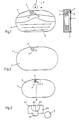
- Fig. 1 shows the cassette housing 1, in which two tape reels 2 carrying the magnetic tape are rotatably mounted.
- the record carrier is accessed from the front 7 of the cassette shown, either by engaging heads 3 shown symbolically or by unthreading the tape and laying it around a head drum.
- the cassette is manually gripped by hand in the rear area 8.
- the cassette housing 1 is closed at the top with the surface 4.
- the surface 4 is in the form of a chip card with an integrated semiconductor memory M and associated with it externally accessible open contacts K are formed.
- the cover 4 is punched out of a commercially available chip card.
- the surface 4 is additionally provided with the transparent marking point 5.
- a light barrier is arranged in the device and cooperates with this marking point 5.
- the marking point 5 is normally transparent, so that the light from the light source of the light barrier reaches the photocell. This is a criterion for the release of the recording, so the recording block is then released.
- the transparent marking point 5 is made opaque or less transparent, e.g. by masking with a foil or blackening with a pen. The light from the light source then no longer reaches the photocell or only at low intensity, which activates an electrical or mechanical recording lock in the device. Due to the position of the contacts K of the memory M and the marking point 5 on the front upper side of the cassette housing 1, these parts can be viewed simultaneously when inserting the cassette.
- the contact spring set in the device is preferably arranged at the front above the cassette receptacle at the beginning. As a result, the contact spring set comes into contact with the contacts K at the start of the insertion of the cassette, so that the characteristic values contained in the memory M are read early on during the insertion process and are fed to the evaluation circuit.
- FIG. 2 shows the cassette housing 1 according to FIG. 1 only without a label print.
- FIG. 3 again shows a cassette according to FIGS. 1, 2, the contacts K, the memory M and the marking point 5 being shown enlarged.
- a total of four contacts K1-K4 are shown, which are connected to the connections of the memory M.
- the contacts K1 - K4 are preferably in one plane with the plane of the surface 4, in order to enable perfect contacting by the contact spring set in the device.
- the surface 4 can also be provided with a circumferential rib 6, which serves to stabilize the surface 4, as a stop and as an additional adhesive surface between the surface 4 and the cassette housing 1.
- the means that are usually provided in the device and press the inserted cassette down onto the device chassis can at the same time contain the contact spring set for contacting the contacts K.
- the contact spring set is preferably designed and arranged such that it contacts the contacts K in the device even when the cassette is finally inserted.
- the housing 1 contains an opening (hole) 9 which forms a marking point 5 at the end.
- Light or a light source is introduced through the opening 9 in the recorder. Marking point 5 in the recorder is thus queried as with a light barrier. If the marking point 5 is transparent, the light beam passes through the opening 9 and the marking point 5 onto a photocell and releases the picture. If a recording lock for the purpose of protection against erasure is desired, the marking point 5 is not made transparent, that is to say it is opaque or less translucent, so that the light beam from the light barrier does not reach the photocell or does not reach it with sufficient intensity.
- a recording lock is then activated by the evaluation electronics, which acts as a deletion protection against inadvertent deletion of an existing recording.
- the transformation of the marking point 5 from the transparent to the non-transparent state can be done, for example, by a sticker or less by blackening with a pen. By looking at the marking point 5, the user can immediately see at any time with the naked eye whether the recording lock is activated or released.
- Fig. 5 shows a cassette 1, as used in VHS.
- the light source 10 arranged on the recorder chassis engages in the hole 9 of the housing 1 from below.
- the light source 10 acts on two photocells 11, 12 via holes opened in the cassette housing 1 during playback operation and, together with the transparent tape section at the beginning and at the end of the tape, causes the end cut-off in the forward or reverse direction.
- the hole 9, which is present anyway, is now additionally designed as a marking point 5, as in FIG. 4.
- the hole 9 is not closed at the end facing away from the light source 10 on the upper side of the cassette 1, but has a transparent cover which, as described in FIG. 1, is made opaque or less translucent to activate the recording lock can be.
- the light beam from the light source 10 passes through the transparent marking point 5 to the photocell 13, which is arranged above the cassette, for example in a VHS cassette.
- the marking point 5 is not made or is made less transparent, so that no light beam or only residual light of low intensity reaches the photocell 13.
- the recording lock 14 then acts on the recording unit 15 so that recording is mechanically or electrically prevented.
- the marking point 5 can in principle be closed, for example by the wall 16 of the housing 1 on the Marking point 5 is not interrupted, but is continuous. Then a transparent marking point 5, which is a prerequisite for the release of the recording, can in principle not be produced by the user in a non-destructive manner.
- the upper cover plate of the cassette housing 1 can also have a surface for sticking on a label.
Landscapes
- Packaging Of Annular Or Rod-Shaped Articles, Wearing Apparel, Cassettes, Or The Like (AREA)
- Credit Cards Or The Like (AREA)
- Debugging And Monitoring (AREA)
Abstract
Description
- Die Erfindung geht aus von einer Kassette gemäß dem Oberbegriff des Anspruchs 1. Eine derartige Kassette ist bekannt durch die DE-PS 29 43 409. Ein derartiges elektronisches Speicherbauelement in einer Kassette dient unter anderem zur Speicherung von kassettentypischen Kennwerten, die beim Aufnahme- oder Wiedergabevorgang bestimmte elektrische oder mechanische Funktionen des Gerätes steuern. Derartige Kennwerte können sich z.B. beziehen auf die Länge des Aufzeichnungsträgers, die Art der Magnetschicht, die Art der aufgezeichneten Signale, auf Vorverzerrungen der Signale und dgl. Der Speicher kann auch Daten über die aufgezeichneten Darbietungen, also ein Inhaltsverzeichnis enthalten. Mit dem Speicher verbundene Kontakte am Kassettengehäuse werden durch einen im Gerät befindlichen Kontaktfedersatz kontaktiert, der die Signale aus dem Speicher liest und einer Auswertschaltung zuführt. Der Speicher und die Kontakte müssen zusätzlich an dem Kassettengehäuse angebracht werden.
- Der Erfindung liegt die Aufgabe zugrunde, eine einfache und billige Herstellbarkeit einer derartigen Kassette mit Speicher zu erzielen und teure Montagetechniken für die Anbringung von Speicher und Kontakten zu vermeiden. Diese Aufgabe wird durch die im Anspruch 1 angegebene Erfindung gelöst. Vorteilhafte Weiterbildungen der Erfindung sind in den Unteransprüchen angegeben.
- Die JP-A-62157391 zeigt ein mit einem Speicher versehenes Blatt zur Aufbringung auf eine Kassette, das flexibel ausgebildet ist. Die Stromversorgung und der Datenaustausch erfolgen dabei über Spulen.
- JP-A-2201789 zeigt eine zur Aufbringung auf eine Kassette geeignete integrierte Schaltung, die in einem Medium versiegelt ist und von außen zugängliche Kontakte aufweist.
- Durch die WO-A-9102355 ist es bekannt, einen Speicher in die Aufnahmesperröffnung am Gehäuse einer Kassette einzusetzen, die in einer neuen Kassette mit einem ausbrechbaren Teil verschlossen ist.
- Bei der Erfindung wird ein auf einem anderen Gebiet bereits gebräuchlicher und als Massenartikel in Millionenstückzahl hergestellter und entsprechend billiger Gegenstand zu einem neuen Zweck angewendet. Vorzugsweise wird eine Chipkarte angewendet, wie sie heute bei Telefonkarten, Scheckkarten oder sonstigen Karten mit gespeichertem Guthaben bekannt ist. Dabei kann eine bekannte und bewährte Fertigungstechnologie zur Realisierung der erfindungsgemäßen Kassette mit einem Speicher ausgenutzt werden. Der erfindungsgemäße Deckel ermöglicht auch ohne großen Mehraufwand, das bei Kassetten gebräuchliche transparente Sichtfenster zur Beurteilung des Bandstandes zu realisieren. Vorzugsweise ist in den Deckel zusätzlich eine transparente Markierstelle eingebaut, die mit einer Lichtschranke im Gerät zusammenwirkt und eine Aufnahmesperre bildet. Die Aufnahme wird dann nur freigegeben, wenn die Markierstelle transparent ist und das Licht von der Lichtquelle zur Fotozelle der Lichtschranke gelangt. Durch Überkleben oder Schwärzen der an sich transparenten Markierstelle kann die Aufnahmesperre im Sinne eines Löschschutzes aktiviert werden.
- Die Kontakte liegen vorzugsweise an der oberen vorderen Kante der Kassette, an der der Zugriff zu dem Aufzeichnungsträger durch Einführung eines Abtastkopfes oder durch Ausfädeln des Bandes erfolgt. Diese Lage der Kontakte hat den Vorteil, daß die zugänglichen, nicht geschützten Kontakte beim Einlegen der Kassette von Hand nicht so leicht berührt und verschmutzt werden. Das beruht darauf, daß die Kassette in der Regel von der Rückseite her erfaßt und von der Vorderseite, an der der Zugriff zum Aufzeichnungsträger erfolgt, eingeschoben wird. Ein weiterer Vorteil besteht darin, daß durch Anordnung eines Kontaktfedersatzes im Gerät unmittelbar am Anfang des Aufnahmeschachtes für die Kassette der Speicher schon von Beginn des Einschiebvorgangs gelesen werden kann und somit die Kennwerte schnell zur Verfügung stehen.
- Vorzugsweise sind die Kontakte an der Oberseite des Kassettengehäuses angeordnet, d.h, auf der Fläche, die dem Benutzer zur Beschriftung vorgegeben ist. Das hat u.a. den Vorteil, daß z.B. ein vom Aufzeichnungsgerät unabhängiges Lesegerät für den Speicher von oben auf die Kontakte aufgesetzt werden kann, ohne daß die Kassette dazu umgedreht werden muß. Ein solches Lesegerät ist beschrieben in der älteren Patentanmeldung P 41 35 371. Vorzugsweise ist auch die genannte als Aufnahmesperre dienende Markierstelle an der Oberseite angeordnet. Dann kann der Benutzer beim Blick auf die Oberseite der Kassette, auf der sich auch das Beschriftungsfeld oder Etikett befindet, gleichzeitig mit bloßen Auge erkennen, ob die Aufnahmesperre aktiviert oder aufgehoben ist.
- Der erfindungsgemäße Deckel kann somit eine Vielzahl von Funktionen erfüllen. Er dient dabei insbesondere als reine Abedeckung des Kassettengehäuses an der Oberseite, zur Aufnahme des Speichers und der Kontakte, bildet das Sichtfenster für die Betrachtung des Bandstandes, dient als Beschriftung- oder Reklamefläche und enthält die transparente Markierstelle für einen Aufnahmeschutz. Die erfindungsgemäße Kassette ist insbesondere als neuartige Kassette für eine digitale Videoaufzeichnung geeignet.
- Die Erfindung wird im folgenden anhand der Zeichnung erläutert. Darin zeigen
- Fig. 1
- in Draufsicht eine erfindungsgemäße Kassette,
- Fig. 2
- dieselbe Kassette ohne Aufdruck und
- Fig. 3
- dieselbe Kassette mit einer vergrößerten Darstellung der Kontakte und des Speichers.
- Fig 4
- eine erfindungsgemäße ausgebildete Kassette und
- Fig. 5
- die Kassette mit der optoelektronischen Auswertung im Recorder.
- Fig. 1 zeigt das Kassettengehäuse 1, in dem zwei das Magnetband tragende Bandspulen 2 drehbar gelagert sind. Der Zugriff zu dem Aufzeichnungsträger erfolgt von der Vorderseite 7 der dargestellten Kassette, entweder durch Eingriff von symbolisch dargestellten Köpfen 3 oder durch Ausfädeln des Bandes und Herumlegen um eine Kopftrommel. Beim manuellen Einlegen der Kassette in das Gerät wird die Kassette normalerweise im hinteren Bereich 8 von Hand erfaßt. Das Kassettengehäuse 1 ist an der Oberseite mit der Oberfläche 4 abgeschlossen. Die Oberfläche 4 ist als Chipkarte mit einem integrierten Halbleiter-Speicher M und diesem zugeordneten, von außen zugänglichen offenen Kontakten K ausgebildet. Der Dekkel 4 ist aus einer handelsüblichen Chipkarte ausgestanzt. Beim Einlegen der Kassette in das Aufzeichnungsgerät gelangt ein im Gerät angeordneter Kontaktfedersatz in Kontakt mit den Kontakten K, wodurch die in dem Speicher M gespeicherten Kennwerte und Daten gelesen und einer Auswertschaltung im Gerät zugeführt werden.
- Die Oberfläche 4 ist zusätzlich mit der transparenten Markierstelle 5 versehen. Im Gerät ist eine Lichtschranke angeordnet, die mit dieser Markierstelle 5 zusammenarbeitet. Die Markierstelle 5 ist normalerweise transparent, so daß das Licht der Lichtquelle der Lichtschranke zu der Fotozelle gelangt. Dieses ist ein Kriterium für die Freigabe der Aufnahme, die Aufnahmesperre ist dann also aufgehoben. Zur Aktivierung der Aufnahmesperre wird die transparente Markierstelle 5 lichtundurchlässig oder weniger transparent gemacht, z.B. durch Abkleben mit einer Folie oder Schwärzung mit einem Stift. Das Licht der Lichtquelle gelangt dann nicht mehr oder nur in geringer Intensität auf die Fotozelle, wodurch eine elektrische oder mechanische Aufnahmesperre im Gerät aktiviert wird. Durch die Lage der Kontakte K des Speichers M und der Markierstelle 5 an der vorderen oberen Seite des Kassettengehäuses 1 können diese Teile beim Einlegen der Kassette gleichzeitig betrachtet werden. Dabei wird gleichzeitig weitestgehend verhindert, daß diese Teile von Hand berührt werden. Der Kontaktfedersatz im Gerät ist vorzugsweise vorn oberhalb des Kassettenaufnahmefaches an dessen Anfang angeordnet. Dadurch gelangt der Kontaktfedersatz bereits beim Beginn des Einschiebens der Kassette in Kontakt mit den Kontakten K, so daß die in dem Speicher M enthaltenden Kennwerte schon früh beim Einschiebvorgang gelesen und der Auswertschaltung zugeführt werden.
- Fig. 2 zeigt das Kassettengehäuse 1 gemäß Fig. 1 lediglich ohne einen Labelaufdruck.
- Fig. 3 zeigt wiederum eine Kassette gemäß Fig. 1, 2, wobei die Kontakte K, der Speicher M und Markierstelle 5 vergrößert gezeichnet sind. Dargestellt sind insgesamt vier Kontakte K1 - K4, die mit den Anschlüssen des Speichers M verbunden sind. Die Kontakte K1 - K4 liegen vorzugsweise in einer Ebene mit der Ebene der Oberfläche 4, um eine einwandfreie Kontaktierung durch den Kontaktfedersatz im Gerät zu ermöglichen.
- Die Oberfläche 4 kann noch mit einer umlaufenden Rippe 6 versehen sein, die zur Stabilisierung der Oberfläche 4, als Anschlag und als zusätzliche Klebefläche zwischen der Oberfläche 4 und Kassettengehäuse 1 dient. Die Mittel, die üblicherweise im Gerät vorgesehen sind und die eingelegte Kassette nach unten auf das Gerätechassis drücken, können gleichzeitig den Kontaktfedersatz zur Kontaktierung der Kontakte K enthalten. Der Kontaktfedersatz ist vorzugsweise so ausgebildet und angeordnet, daß er auch im endgültig eingelegten Zustand der Kassette in das Gerät die Kontakte K kontaktiert.
- In Fig. 4 sind in dem Kassettengehäuse 1 zwei Bandspulen 2,2' drehbar gelagert, auf denen das Magnetband 8 aufgewickelt ist. Das Gehäuse 1 enthält eine Öffnung(Loch) 9, die am Ende eine Markierstelle 5 bildet. Durch die Öffnung 9 wird im Recorder Licht oder eine Lichtquelle eingeführt. Damit wird die Markierstelle 5 im Recorder wie mit einer Lichtschranke abgefragt. Wenn die Markierstelle 5 transparent ist, gelangt der Lichtstrahl durch die Öffnung 9 und die Markierstelle 5 auf eine Fotozelle und gibt die Aufnahme frei. Wenn eine Aufnahmesperre zum Zwecke des Löschchutzes gewünscht ist, wird die Markierstelle 5 nicht transparent, also lichtundurchlässig oder weniger lichtdurchlässig gemacht, so daß der Lichtstrahl der Lichtschranke die Fotozelle nicht mehr oder nicht in ausreichender Intensität erreicht. Durch die Auswertelektronik wird dann eine Aufnahmesperre aktiviert, die als Löschschutz gegen unbeabsichtigtes Löschen einer bereits vorhandenen Aufnahme wirkt. Die Umwandlung der Markierstelle 5 von dem transparenten in den nichttransparenten Zustand kann z.B. durch einen Aufkleber oder weniger durch Schwärzung mit einem Stift erfolgen. Der Benutzer kann durch Betrachten der Markierstelle 5 jederzeit sofort mit dem bloßen Auge erkennen, ob die Aufnahmesperre aktiviert oder aufgehoben ist.
- Fig. 5 zeigt eine Kassette 1, wie sie bei VHS verwendet wird. In das Loch 9 des Gehäuses 1 greift von unten die am Recorderchassis angeordnete Lichtquelle 10 ein. Die Lichtquelle 10 wirkt über beim Abspielbetrieb geöffnete Löcher im Kassettengehäuse 1 auf zwei Fotozellen 11, 12 und bewirkt zusammen mit dem transparenten Bandabschnitt am Beginn und am Ende des Bandes jeweils die Endabschaltung beim Vorlauf oder Rücklauf. Das ohnehin vorhandene Loch 9 ist jetzt wie in Fig. 4 zusätzlich als Markierstelle 5 ausgebildet. Im Gegensatz zu bekannten Kassetten ist das Loch 9 an dem der Lichtquelle 10 abgewandten Ende an der Oberseite der Kassette 1 nicht verschlossen, sondern weist eine transparente Abdekkung auf, die, wie in Fig. 1 beschrieben, zur Aktivierung der Aufnahmesperre lichtundurchlässig oder weniger lichtdurchlässig gemacht werden kann.
- Wenn eine Aufnahmesperre nicht gewünscht ist, gelangt der Lichtstrahl von der Lichtquelle 10 über die transparente Markierstelle 5 auf die Fotozelle 13, die z.B. bei einer VHS-Kassette oberhalb der Kassette angeordnet ist. Diese steuert die Aufnahmesperre 14 für die Aufzeichnungseinheit 15 so, daß eine Aufnahme möglich ist. Zur Aktivierung der Aufnahmesperre wird die Markierstelle 5 nicht oder weniger transparent gemacht, so daß kein Lichtstrahl oder nur Restlicht geringer Intensität auf die Fotozelle 13 gelangt. Die Aufnahmesperre 14 wirkt dann auf die Aufzeichnungseinheit 15 so ein, daß eine Aufnahme mechanisch oder elektrisch verhindert ist. Bei vorbespielten, käuflichen oder zu leihenden Kassetten, bei denen ein versehentliches Löschen grundsätzlich verhindert werden soll, kann die Markierstelle 5 grundsätzlich verschlossen sein, indem z.B. die Wand 16 des Gehäuses 1 an der Markierstelle 5 nicht unterbrochen, sondern durchgehend ist. Dann kann eine transparente Markierstelle 5, die Voraussetzung für die Freigabe der Aufnahme ist, vom Benutzer grundsätzlich nicht zerstörungsfrei hergestellt werden.
- Es ist auch möglich, die obere Abdeckplatte des Kassettengehäuses 1 ganz oder im wesentlichen ganz transparent auszubilden. Eine teilweise transparente Ausbildung ist ohnehin in der Praxis notwendig, um ein Sichtfenster zum Erkennen der Standes der Bandwickel zu bilden. Die obere Abdeckplatte bildet dann mit ihrem transparenten Bereich einerseits das Sichtfenster und andererseits die Markierstelle 5. Zusätzlich kann der Deckel noch eine Fläche zum Aufkleben eines Etikettes aufweisen.
Claims (6)
- Kassette mit einem Aufzeichnungsträger für ein Aufzeichnungsgerät, bei der an einer Oberfläche des Kassettengehäuses (1) ein Halbleiterspeicher (M) mit vom Gerät elektrisch kontaktierbaren Kontakten für Kennwerte der Kassette und/oder andere Daten angeordnet ist, dadurch gekennzeichnet, daß der Speicher (M) in einem Gehäuseteil integriert ist, indem ein ausgestantztes Speicher-Chipkartenteil eine Gehäusewand des Kassettengehäuses bildet.
- Kassette nach Anspruch 1, dadurch gekennzeichnet, daß die Kontakte (K) nebeneinander nahe der oder an der vorderen oberen Kante des Kassettengehäuses (1) liegen, an der im Gerät der Zugriff zu dem Aufzeichnungsträger erfolgt.
- Kassette nach Anspruch 1, dadurch gekennzeichnet, daß die Oberfläche (4) eine Markierstelle (5) mit veränderbarer Lichtdurchlässigkeit aufweist, die zusammen mit einer im Gerät vorhandenen Lichtschranke als wahlweise entsprechend der jeweiligen Lichtdurchlässigkeit aktivierbare oder aufhebbare Aufnahmesperre dient.
- Kassette nach Anspruch 3, dadurch gekennzeichnet, daß Mittel vorgesehen sind, mit denen eine transparent hergestellte Markierstelle (5) verschließbar oder nicht bzw. weniger transparent machbar ist.
- Kassette nach Anspruch 1, dadurch gekennzeichnet, daß an dem Kassettengehäuse (1) Mittel vorgesehen sind, die eine zerstörerisch hohe statische Aufladung der Kontakte (K) des Speichers (M) an der Kassette verhindern.
- Aufzeichnungsgerät mit einer Kassette nach Anspruch 1, dadurch gekennzeichnet, daß im Gerät ein Kontaktfedersatz vorgesehen ist, der die Kontakte (K) der Kassette bei oder nach deren Einlegen kontaktiert und an eine Auswertschaltung angeschlossen ist.
Applications Claiming Priority (15)
| Application Number | Priority Date | Filing Date | Title |
|---|---|---|---|
| DE19924200436 DE4200436A1 (de) | 1992-01-10 | 1992-01-10 | Kassette mit einem aufzeichnungstraeger fuer ein aufzeichnungsgeraet |
| DE4200436 | 1992-01-10 | ||
| DE4200435 | 1992-01-10 | ||
| DE19924200435 DE4200435A1 (de) | 1992-01-10 | 1992-01-10 | Kassette mit einem aufzeichnungstraeger fuer ein aufzeichnungsgeraet |
| DE4204180 | 1992-02-13 | ||
| DE19924204180 DE4204180C2 (de) | 1992-02-13 | 1992-02-13 | Kassette mit einem Aufzeichnungsträger und einem Speicher, Speicher sowie Rekorder für eine derartige Kassette |
| DE4207211 | 1992-03-06 | ||
| DE19924207211 DE4207211A1 (de) | 1992-03-06 | 1992-03-06 | Kassette mit einem aufzeichnungstraeger und einer schutzhuelle |
| DE4207381 | 1992-03-09 | ||
| DE19924207381 DE4207381A1 (de) | 1992-03-09 | 1992-03-09 | Kassette mit einem aufzeichnungstraeger und einem halbleiterspeicher |
| DE4224116 | 1992-07-22 | ||
| DE4224116 | 1992-07-22 | ||
| DE4224828 | 1992-07-23 | ||
| DE19924224828 DE4224828A1 (de) | 1992-07-27 | 1992-07-27 | Kassette mit einem Aufzeichnungsträger für ein Aufzeichnungsgerät |
| PCT/EP1992/002994 WO1993014501A1 (de) | 1992-01-10 | 1992-12-24 | Kassette mit einem aufzeichnungsträger für ein aufzeichnungsgerät |
Publications (2)
| Publication Number | Publication Date |
|---|---|
| EP0620945A1 EP0620945A1 (de) | 1994-10-26 |
| EP0620945B1 true EP0620945B1 (de) | 1997-03-05 |
Family
ID=27561558
Family Applications (1)
| Application Number | Title | Priority Date | Filing Date |
|---|---|---|---|
| EP93901720A Expired - Lifetime EP0620945B1 (de) | 1992-01-10 | 1992-12-24 | Kassette mit einem aufzeichnungsträger für ein aufzeichnungsgerät |
Country Status (7)
| Country | Link |
|---|---|
| EP (1) | EP0620945B1 (de) |
| JP (1) | JPH07502854A (de) |
| KR (1) | KR940704047A (de) |
| DE (1) | DE59208151D1 (de) |
| ES (1) | ES2098022T3 (de) |
| HK (1) | HK72397A (de) |
| WO (1) | WO1993014501A1 (de) |
Families Citing this family (8)
| Publication number | Priority date | Publication date | Assignee | Title |
|---|---|---|---|---|
| KR100262921B1 (ko) * | 1992-10-22 | 2000-08-01 | 이데이 노부유끼 | 기록매체카셋트에기록된내용을보안하기위한장치와방법 |
| TW230252B (en) * | 1993-03-17 | 1994-09-11 | Sony Co Ltd | A cassette having a recording medium and a recording/reproducing apparatus for use with the cassette |
| US6101070A (en) * | 1993-09-30 | 2000-08-08 | Sony Corporation | Method and apparatus for determining information and a cassette for use therewith |
| EP0884730B1 (de) * | 1993-09-30 | 2006-02-08 | Sony Corporation | Kassetten mit Speichern |
| JPH10144048A (ja) * | 1996-11-12 | 1998-05-29 | Sony Corp | カセットラベル、および、ビデオカセットテープ |
| US7123444B1 (en) | 1998-05-22 | 2006-10-17 | Tanberg Data Asa | Tape cassette having an optical signal receiver and a memory for storing information optically transmitted into the cassette |
| KR100565047B1 (ko) * | 1999-10-01 | 2006-03-30 | 삼성전자주식회사 | 테이프 레코더 장착용 미디어 스토리지 카드 착탈 카세트 |
| GB2367182B (en) | 2000-09-20 | 2004-05-26 | Hewlett Packard Co | Improvements in and relating to data protection |
Family Cites Families (8)
| Publication number | Priority date | Publication date | Assignee | Title |
|---|---|---|---|---|
| US4057839A (en) * | 1975-12-22 | 1977-11-08 | Mfe Corporation | Tape cassette drive |
| BE871596A (fr) * | 1978-10-27 | 1979-02-15 | Staar Sa | Dispositif de memorisation de la position instantanee d'une bande magnetique contenue dans une cassette. |
| DE3812747A1 (de) * | 1988-04-16 | 1989-10-26 | Ostertag Ulrich | Magnetbandkassette sowie magnetbandgeraet |
| GB8809223D0 (en) * | 1988-04-19 | 1988-05-25 | British Broadcasting Corp | Cassette for sequential access recording medium & apparatus for use therewith |
| US4995029A (en) * | 1988-10-24 | 1991-02-19 | Tdk Corporation | Optical disk identifying method, manufacture of cartridge-enclosed optical disks, and optical disk cartridges |
| AT391220B (de) * | 1988-12-14 | 1990-09-10 | Philips Nv | Aufzeichnungs- und/oder wiedergabesystem und kassette fuer ein solches system |
| DK385489D0 (da) * | 1989-08-07 | 1989-08-07 | Bang & Olufsen As | Optage- og gengivesystem, navnlig videosystem, med baandkassetter |
| JP2501803Y2 (ja) * | 1990-02-02 | 1996-06-19 | ソニー株式会社 | カセット収納ケ―ス |
-
1992
- 1992-12-24 EP EP93901720A patent/EP0620945B1/de not_active Expired - Lifetime
- 1992-12-24 KR KR1019940702362A patent/KR940704047A/ko not_active Application Discontinuation
- 1992-12-24 WO PCT/EP1992/002994 patent/WO1993014501A1/de active IP Right Grant
- 1992-12-24 DE DE59208151T patent/DE59208151D1/de not_active Expired - Fee Related
- 1992-12-24 JP JP5511983A patent/JPH07502854A/ja active Pending
- 1992-12-24 ES ES93901720T patent/ES2098022T3/es not_active Expired - Lifetime
-
1997
- 1997-05-29 HK HK72397A patent/HK72397A/xx not_active IP Right Cessation
Also Published As
| Publication number | Publication date |
|---|---|
| DE59208151D1 (de) | 1997-04-10 |
| JPH07502854A (ja) | 1995-03-23 |
| KR940704047A (ko) | 1994-12-12 |
| ES2098022T3 (es) | 1997-04-16 |
| HK72397A (en) | 1997-06-06 |
| EP0620945A1 (de) | 1994-10-26 |
| WO1993014501A1 (de) | 1993-07-22 |
Similar Documents
| Publication | Publication Date | Title |
|---|---|---|
| DE69614726T2 (de) | Datenspeicheranordnung und diese verwendende Datenverarbeitungsanordnung | |
| DE69833290T2 (de) | Speicherkarte | |
| DE69927616T2 (de) | Aufbewahrungsbehälter für kasseten | |
| DE69014956T2 (de) | Plattenkassette. | |
| DE69323927T2 (de) | Aufzeichnungskassette und Aufnahme-/Wiedergabegerät | |
| DE69520717T2 (de) | Kassette, Aufbewahrungsbehälter, und Etikett für dergleiche Kassette und Aufbewahrungsbehälter | |
| DE2502337C3 (de) | Mikrofilmkarte | |
| EP0620945B1 (de) | Kassette mit einem aufzeichnungsträger für ein aufzeichnungsgerät | |
| DE8124507U1 (de) | "tonillustriertes, gebundenes buch" | |
| DE69519552T2 (de) | Plattenkassette | |
| DE3836837A1 (de) | Plattenkassette hoher packungsdichte mit einem schreibschutzmechanismus | |
| DE69131999T2 (de) | Gehäuse für eine rechteckige Kassette | |
| DE60106303T2 (de) | Plattenkassette und Verfahren zum Laden von Plattenkassetten | |
| DE4340601A1 (de) | Plattenkassette | |
| DE69935830T2 (de) | Plattenkassette | |
| EP0653082A1 (de) | Kontaktmittel, produkt mit diesem kontaktmittel und gerät zur aufnahme dieses produkts. | |
| DE60224819T2 (de) | Kassette als behälter für ein aufzeichnungsmedium | |
| EP0609290B1 (de) | Lesegerät für einen statischen speicher einer kassette | |
| EP0626095B1 (de) | Ständer mit fächern für aufzeichnungsträger enthaltende kassetten | |
| DE4200436A1 (de) | Kassette mit einem aufzeichnungstraeger fuer ein aufzeichnungsgeraet | |
| DE69329238T2 (de) | Plattenkasettenbehälter, und Platten-Registrier und/oder Wiedergabe-Apparat der diesen Behälter enhält. | |
| DE9216771U1 (de) | Hülle zur Aufnahme von insbesondere Compact-Discs | |
| DE4224828A1 (de) | Kassette mit einem Aufzeichnungsträger für ein Aufzeichnungsgerät | |
| DE19519346A1 (de) | Speicherkartenhalter | |
| EP0594665B1 (de) | System zur wiedergabeprogrammierung von auf einem aufzeichnungsträger gespeicherten aufzeichnungsbeiträgen |
Legal Events
| Date | Code | Title | Description |
|---|---|---|---|
| PUAI | Public reference made under article 153(3) epc to a published international application that has entered the european phase |
Free format text: ORIGINAL CODE: 0009012 |
|
| 17P | Request for examination filed |
Effective date: 19940701 |
|
| AK | Designated contracting states |
Kind code of ref document: A1 Designated state(s): DE ES FR GB IT |
|
| 17Q | First examination report despatched |
Effective date: 19950717 |
|
| GRAG | Despatch of communication of intention to grant |
Free format text: ORIGINAL CODE: EPIDOS AGRA |
|
| GRAH | Despatch of communication of intention to grant a patent |
Free format text: ORIGINAL CODE: EPIDOS IGRA |
|
| GRAH | Despatch of communication of intention to grant a patent |
Free format text: ORIGINAL CODE: EPIDOS IGRA |
|
| GRAA | (expected) grant |
Free format text: ORIGINAL CODE: 0009210 |
|
| ITF | It: translation for a ep patent filed | ||
| AK | Designated contracting states |
Kind code of ref document: B1 Designated state(s): DE ES FR GB IT |
|
| GBT | Gb: translation of ep patent filed (gb section 77(6)(a)/1977) |
Effective date: 19970305 |
|
| REF | Corresponds to: |
Ref document number: 59208151 Country of ref document: DE Date of ref document: 19970410 |
|
| REG | Reference to a national code |
Ref country code: ES Ref legal event code: FG2A Ref document number: 2098022 Country of ref document: ES Kind code of ref document: T3 |
|
| ET | Fr: translation filed | ||
| PGFP | Annual fee paid to national office [announced via postgrant information from national office to epo] |
Ref country code: GB Payment date: 19971211 Year of fee payment: 6 |
|
| PGFP | Annual fee paid to national office [announced via postgrant information from national office to epo] |
Ref country code: FR Payment date: 19971218 Year of fee payment: 6 |
|
| PGFP | Annual fee paid to national office [announced via postgrant information from national office to epo] |
Ref country code: ES Payment date: 19971230 Year of fee payment: 6 |
|
| PLBE | No opposition filed within time limit |
Free format text: ORIGINAL CODE: 0009261 |
|
| STAA | Information on the status of an ep patent application or granted ep patent |
Free format text: STATUS: NO OPPOSITION FILED WITHIN TIME LIMIT |
|
| PGFP | Annual fee paid to national office [announced via postgrant information from national office to epo] |
Ref country code: DE Payment date: 19980224 Year of fee payment: 6 |
|
| 26N | No opposition filed | ||
| PG25 | Lapsed in a contracting state [announced via postgrant information from national office to epo] |
Ref country code: GB Free format text: LAPSE BECAUSE OF NON-PAYMENT OF DUE FEES Effective date: 19981224 |
|
| GBPC | Gb: european patent ceased through non-payment of renewal fee |
Effective date: 19981224 |
|
| PG25 | Lapsed in a contracting state [announced via postgrant information from national office to epo] |
Ref country code: FR Free format text: LAPSE BECAUSE OF NON-PAYMENT OF DUE FEES Effective date: 19990831 |
|
| REG | Reference to a national code |
Ref country code: FR Ref legal event code: ST |
|
| PG25 | Lapsed in a contracting state [announced via postgrant information from national office to epo] |
Ref country code: DE Free format text: LAPSE BECAUSE OF NON-PAYMENT OF DUE FEES Effective date: 19991001 |
|
| PG25 | Lapsed in a contracting state [announced via postgrant information from national office to epo] |
Ref country code: ES Free format text: LAPSE BECAUSE OF NON-PAYMENT OF DUE FEES Effective date: 19991225 |
|
| REG | Reference to a national code |
Ref country code: ES Ref legal event code: FD2A Effective date: 20000114 |
|
| PG25 | Lapsed in a contracting state [announced via postgrant information from national office to epo] |
Ref country code: IT Free format text: LAPSE BECAUSE OF NON-PAYMENT OF DUE FEES;WARNING: LAPSES OF ITALIAN PATENTS WITH EFFECTIVE DATE BEFORE 2007 MAY HAVE OCCURRED AT ANY TIME BEFORE 2007. THE CORRECT EFFECTIVE DATE MAY BE DIFFERENT FROM THE ONE RECORDED. Effective date: 20051224 |