EP0620100A2 - Umstülpverfahren für einen Auskleidungsschlauch - Google Patents
Umstülpverfahren für einen Auskleidungsschlauch Download PDFInfo
- Publication number
- EP0620100A2 EP0620100A2 EP94301035A EP94301035A EP0620100A2 EP 0620100 A2 EP0620100 A2 EP 0620100A2 EP 94301035 A EP94301035 A EP 94301035A EP 94301035 A EP94301035 A EP 94301035A EP 0620100 A2 EP0620100 A2 EP 0620100A2
- Authority
- EP
- European Patent Office
- Prior art keywords
- tubular liner
- liner bag
- pipe
- bag
- air
- Prior art date
- Legal status (The legal status is an assumption and is not a legal conclusion. Google has not performed a legal analysis and makes no representation as to the accuracy of the status listed.)
- Granted
Links
Images


Classifications
-
- F—MECHANICAL ENGINEERING; LIGHTING; HEATING; WEAPONS; BLASTING
- F16—ENGINEERING ELEMENTS AND UNITS; GENERAL MEASURES FOR PRODUCING AND MAINTAINING EFFECTIVE FUNCTIONING OF MACHINES OR INSTALLATIONS; THERMAL INSULATION IN GENERAL
- F16L—PIPES; JOINTS OR FITTINGS FOR PIPES; SUPPORTS FOR PIPES, CABLES OR PROTECTIVE TUBING; MEANS FOR THERMAL INSULATION IN GENERAL
- F16L55/00—Devices or appurtenances for use in, or in connection with, pipes or pipe systems
- F16L55/16—Devices for covering leaks in pipes or hoses, e.g. hose-menders
- F16L55/162—Devices for covering leaks in pipes or hoses, e.g. hose-menders from inside the pipe
- F16L55/165—Devices for covering leaks in pipes or hoses, e.g. hose-menders from inside the pipe a pipe or flexible liner being inserted in the damaged section
- F16L55/1651—Devices for covering leaks in pipes or hoses, e.g. hose-menders from inside the pipe a pipe or flexible liner being inserted in the damaged section the flexible liner being everted
-
- B—PERFORMING OPERATIONS; TRANSPORTING
- B29—WORKING OF PLASTICS; WORKING OF SUBSTANCES IN A PLASTIC STATE IN GENERAL
- B29C—SHAPING OR JOINING OF PLASTICS; SHAPING OF MATERIAL IN A PLASTIC STATE, NOT OTHERWISE PROVIDED FOR; AFTER-TREATMENT OF THE SHAPED PRODUCTS, e.g. REPAIRING
- B29C63/00—Lining or sheathing, i.e. applying preformed layers or sheathings of plastics; Apparatus therefor
- B29C63/26—Lining or sheathing of internal surfaces
- B29C63/34—Lining or sheathing of internal surfaces using tubular layers or sheathings
- B29C63/36—Lining or sheathing of internal surfaces using tubular layers or sheathings being turned inside out
-
- F—MECHANICAL ENGINEERING; LIGHTING; HEATING; WEAPONS; BLASTING
- F16—ENGINEERING ELEMENTS AND UNITS; GENERAL MEASURES FOR PRODUCING AND MAINTAINING EFFECTIVE FUNCTIONING OF MACHINES OR INSTALLATIONS; THERMAL INSULATION IN GENERAL
- F16L—PIPES; JOINTS OR FITTINGS FOR PIPES; SUPPORTS FOR PIPES, CABLES OR PROTECTIVE TUBING; MEANS FOR THERMAL INSULATION IN GENERAL
- F16L57/00—Protection of pipes or objects of similar shape against external or internal damage or wear
Definitions
- the present invention relates to a method for everting a tubular liner bag into a pipe in an attempt to line the pipe by applying the tubular liner bag on the inner wall of the pipe. (The meaning of the term "everting” as used herein shall be explained immediately.)
- this method of pipe repair comprises inserting a sufficiently long tubular flexible liner bag into the pipe to be repaired by means of a pressurized fluid, like air and water.
- the tubular liner bag is made of a flexible resin-absorbent material impregnated with a thermosetting resin, and has the outer surface covered with an impermeable plastic film.
- the tubular flexible liner bag is closed at one end and open at the other; the tubular flexible liner bag is first flattened, then, the closed end of the tubular liner bag is tied to a control rope; the open end of the tubular liner bag is made to gape wide and hooked (anchored) at the end of the defective or old pipe in a manner such that the wide-opened end of the liner completely and fixedly covers and closes the pipe end; a portion of the liner is pushed into the pipe; then, the pressurized fluid is applied to the said portion of the tubular liner such that the fluid urges the tubular liner to enter the pipe.
- the everted tubular liner is pressed against the inner wall of the pipe by the said pressurized fluid, and the tubular flexible liner is hardened as the thermosetting resin impregnated in the liner is heated, which is effected by heating the fluid filling the tubular liner bag by means of a hot steam, etc. It is thus possible to line the inside wall of the defective or old pipe with a rigid liner without digging the ground and disassembling the pipe sections.
- the pressurized fluid can be anything, but the most frequently used is pressurized water, then compressed air is the next most frequently used, and on many occasions pressurized water and compressed air are used in combination.
- the apparatus installed on the ground to effect everting was complicated and large in size.
- the reference numeral 101 designates a tubular liner bag soaked with thermosetting resin, and two closed air bags 102 and 103 are partially attached to the outer surface (before everting) of the liner bag 101.
- one end of the tubular liner bag 101 is anchored on a tubular brim 106a of a support frame 106, as shown and turned inside the brim 106a a little; next, into the small pocket caused by this turning, water is charged from a water hose 107, whereby the tubular liner bag 101 is everted and enters partially into a manhole 111, which is a vertical entrance to the pipe 110.
- the tubular liner bag 101 hits upon the wall of the pipe 110, the head of the bag 101 is turned to that side of the pipe 10 which is to be lined, and the bag 101 is everted into said side of the pipe 110.
- the air bags 102, 103 which are flattened at the moment, also get into the pipe 110, and, incidentally, the positions at which the air bags 102, 103 are attached to the tubular liner bag 101 are such that when the air bags 102, 103 get into the pipe 110, the air bag 103 stays in the vicinity of the lower end of the manhole 111 and the air bag 102 stays at a location a little farther from the air bag 103, and furthermore, the air bags 102, 103 are attached to the opposite sides of the flattened uneverted tubular liner bag 101, as shown in Fig.
- compressed air is supplied from a compressor, not shown, into the air bags 102, 103 via air hoses 104, 105, respectively, whereupon the air bags 102, 103 inflate inside the everted part of the tubular liner bag 101 which has been inserted in the pipe 110, and as the result, the uneverted part of the tubular liner bag 101 is forced to undulate as it runs and describe a locus in a shape of a fallen letter "S", as seen in Fig. 5. Then the supply of water is ceased.
- compressed air is supplied from a compressor, not shown, via an air hose 108 to dispel some water and form a closed space S filled with compressed air in the head portion of the tubular liner bag 101.
- the closed space S expands, but it does not do so backward, because the water pressure it confronts at the water level formed between the air bags 102 and 103 is greater than the pressure required to force the tubular liner bag 101 to evert.
- the compressed air does not flow backward and up along the manhole, but causes the tubular liner bag 101 to start everting again prompted by the increased pressure in the closed space S, and thus the tubular liner bag 101 advances in the pipe 110 leftward, as seen in Fig. 5.
- the closed space S is formed in the tubular liner bag 101 inserted in the pipe 110, and everting is effected by means of the pressure of the compressed air supplied to this closed space S, so that it is possible to reduce the size of the apparatus for eversion installed on the ground and eversion itself can be conducted with high operation efficiency and ease.
- this eversion method requires that the air bags 102, 103 be attached to the tubular liner bag 101, so that the preparation of tubular liner bag 101 complete with the air bags is complicated and the manufacturing cost is increased.
- the present invention was contrived in view of the above problems, and it is, therefore, an object of the invention to provide a new method for everting a tubular liner bag which method is so contrived that the tubular liner bag can be manufactured at a low cost and can be everted effectively and easily with a compact everting apparatus.
- an improved method for everting a tubular liner bag into a pipe consisting of the steps of: (a) preparing the tubular liner bag such that one end of an air hose whose other end is connected to an air compressor is attached to a suitable position of the outer surface (before everting) of the liner bag; (b) everting the tubular liner bag by means of water pressure into a vertical entrance to the pipe; (c) turning the head of the tubular liner bag toward that side of the pipe which is to be lined, when the head of the tubular liner bag hits upon the inner wall of the pipe; (d) everting the tubular liner bag substantially deep into the pipe; (e) stopping eversion of the tubular liner bag; (f) deforming the everted tubular liner bag such that it is roughly shaped like a letter "J" with the head portion of the tubular liner bag corresponding to the toe of the J-letter, and such that when compressed air of a pressure not
- the step (f) consists of the substeps of: (i) laying an inflatable air bag adapted to inflate when supplied with compressed air in the pipe at an optimum location, (ii) supplying the inflatable air bag with compressed air to thereby inflate the air bag; and (iii) lowering a press means down in the vertical entrance to depress an optimum location of the everted tubular liner bag, and that in the step (d) the tubular liner bag is everted until the eversion head thereof gets substantially beyond the air bag laid in the pipe.
- the head of the tubular liner bag is turned toward upstream side of the pipe, and the step (f) consists of a single substep of (i) lowering a press means down in the vertical entrance to depress an optimum location of the everted tubular liner bag.
- the air bag is not attached to the tubular liner bag, but is merely sandwiched between the inner wall of the pipe and the tubular liner bag, so that there will not occur the problem with the conventional practice that the air bag is torn apart from the tubular liner bag to cause the tubular liner bag to burst.
- the closed space is formed as compressed air is supplied into the tubular liner bag which is substantially inserted in the pipe, and the further everting of the tubular liner bag in the pipe is effected by means of the high pressure of the compressed air supplied into the closed space, so that the apparatus for eversion installed on the ground can be small and compact, and it is possible to conduct the eversion with high operation efficiency and ease.
- the present invention attains the above-mentioned objects.
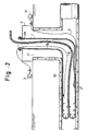
- Figs. 1 through 3 are sectional side views of a site in which a pipe is repaired, each illustrating a respective step of a tubular liner bag eversion of a first embodiment of the inventive method.
- this first embodiment of the inventive method wherein a tubular liner bag 1 soaked with thermosetting resin is inserted by eversion into a pipe 10, requires a closed air bag 2 (hereinafter merely “air bag 2") to be placed in the pipe 10 at a location which is a predetermined distance away from a manhole 11, from which the pipe 10 is lined.
- this air bag 2 which is at the moment empty and flat, is inflatable and deflatable, and is a plastic bag made of a material such as polyvinylchloride, urethane, ethylvinyl acetate, etc.
- the air bag 2 is connected via an air hose 3 to a compressor 4 installed on the ground.
- a tubular liner bag 1 is anchored on a tubular brim 5a of a support frame 5, as shown in Fig. 1, and turned inside the brim 5a a little; then, into the small pocket caused by this turning, water is charged from a water hose 6.
- the water pressure causes the tubular liner bag 1 to evert and enter into the manhole 11.
- the head of the tubular liner bag 1 is turned toward that side of the pipe 10 which is to be lined, and the tubular liner bag 1 is everted farther to enter into the pipe 10, as shown in broken line in Fig. 1.
- one end of an air hose 8 whose other end is connected to a compressor 7 installed on the ground, is attached to the outer surface (before everting) of the liner bag 1, and as the tubular liner bag 1 is everted, as shown in Fig. 2, the air hose 8 is drawn into the tubular liner bag 1 so that its attached end opens in the everted part of the tubular liner bag 1.
- the compressor 7 is driven to supply compressed air to the tubular liner bag 1 via the air hose 8; then the supplied compressed air pushes away some water and forms a closed space S filled with the compressed air in the head portion of the tubular liner bag 1.
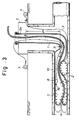
- the water inside the tubular liner bag 1 has two levels one higher than the other by ⁇ h, which is equal to P/ ⁇ , ⁇ being the specific gravity of water, and P being the internal pressure of the closed space S.
- ⁇ h the specific gravity of water
- P being the internal pressure of the closed space S.
- the closed space S expands, but it does not do so backward, because the water pressure it confronts at the lower water level is greater than the pressure required to force the tubular liner bag 1 to evert.
- the compressed air does not flow backward and up along the manhole 11, but causes the tubular liner bag 1 to evert farther prompted by the increased pressure in the closed space S; thus the tubular liner bag 1 advances leftward in the pipe 10, as shown in broken line in Fig. 3.
- the air bag 2 is not attached to the tubular liner bag 1, and is merely sandwiched between the inner wall of the pipe 10 and the tubular liner bag 1, so that there will not occur the problem with the conventional practice that the air bag 2 is torn apart from the tubular liner bag 1 to cause the tubular liner bag 1 to burst.
- the closed space S is formed as compressed air is supplied into the tubular liner bag 1 which is partially inserted in the pipe 10, and the further everting of the tubular liner bag 1 in the pipe 10 is effected by means of the high pressure of the compressed air supplied into the closed space S, so that the apparatus for eversion installed on the ground can be small and compact, and it is possible to conduct the eversion with high operation efficiency and ease.
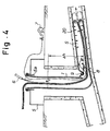
- FIG. 4 is a sectional side view of a site of a pipe repair useful to explain the eversion procedure of the second embodiment, and in Fig. 4 the same reference numerals are used for elements which have corresponding elements in Figs. 1 through 3.
- This second embodiment is applied to cases wherein the pipe 20 to be lined with the tubular liner bag 1 by eversion has a small inner diameter of for ⁇ 200 to ⁇ 350 mm, and has a slope of 20 ⁇ or greater, as shown in Fig. 4. According to the eversion procedure of this embodiment, the air bag 2 of the first embodiment can be dispensed with.
- tubular liner bag 1 With reference to Fig. 4, one end of the tubular liner bag 1 is anchored on a tubular brim 5a of a support frame 5, as shown in Fig. 4, and turned inside the brim 5a a little; then, into the small pocket caused by this turning, water is charged from a water hose 6.
- the water pressure causes the tubular liner bag 1 to evert and enter into the manhole.
- the tubular liner bag 1 is everted further and hits upon the bottom wall of the sloped pipe 20, it is turned to enter into the upstream side of the pipe 20, i.e., rightward, as seen in Fig. 4.
- the tubular liner bag 1 is everted farther into the pipe 20 until the head of the tubular liner bag 1 is substantially inserted in the sloped pipe 20.
- the supply of water is stopped, and the tubular liner bag 1 stops everting.
- one end of an air hose 8 whose other end is connected to a compressor 7 installed on the ground, is attached to the outer surface (before everting) of the liner bag 1, and as the tubular liner bag 1 is everted, as shown in Fig. 4, the air hose 8 is drawn into the tubular liner bag 1 so that its attached end opens in the everted part of the tubular liner bag 1.
- a cylindrical bar 9 which is held in such a manner that it stands vertical to the sheet of Fig. 4, is lowered in the manhole and pressed on a portion of the tubular liner bag 1; as a result, the tubular liner bag 1 is depressed at the portion where it is pressed. Incidentally, there are cases where it is not necessary to depress the tubular liner bag 1 with the bar 9.
- the compressor 7 is driven to supply compressed air to the tubular liner bag 1 via the air hose 8; then the supplied compressed air pushes away some water and forms a closed space S in the head portion of the everted tubular liner bag 1.
- the water inside the tubular liner bag 1 has two levels one higher than the other by ⁇ h, which is equal to P/ ⁇ , ⁇ being the specific gravity of water, and P being the internal pressure of the closed space S.
- ⁇ h the specific gravity of water
- P being the internal pressure of the closed space S.
- the closed space S expands, but it does not do so backward, because the water pressure it confronts at the lower water level is greater than the pressure required to force the tubular liner bag 1 to evert.
- the compressed air does not flow backward and up along the manhole, but causes the tubular liner bag 1 to evert farther prompted by the increased pressure in the closed space S; thus the tubular liner bag 1 advances upstream in the pipe 20, as shown in broken line in Fig. 4.
- the closed space S is formed as compressed air is supplied into the tubular liner bag, and the everting of the tubular liner bag is effected by means of the high pressure of the compressed air supplied into the closed space S, so that the apparatus for eversion installed on the ground can be small and compact, and it is possible to conduct the eversion with high operation efficiency and ease.
- thermosetting resin may be replaced by another hardenable resin such as photosetting resin.
- photosetting resin may be replaced by another hardenable resin such as photosetting resin.
Landscapes
- Engineering & Computer Science (AREA)
- General Engineering & Computer Science (AREA)
- Mechanical Engineering (AREA)
- Manufacturing & Machinery (AREA)
- Lining Or Joining Of Plastics Or The Like (AREA)
- Sink And Installation For Waste Water (AREA)
- Protection Of Pipes Against Damage, Friction, And Corrosion (AREA)
Applications Claiming Priority (3)
| Application Number | Priority Date | Filing Date | Title |
|---|---|---|---|
| JP5235693 | 1993-03-12 | ||
| JP5052356A JP2554436B2 (ja) | 1993-03-12 | 1993-03-12 | 管ライニング材の反転方法 |
| JP52356/93 | 1993-03-12 |
Publications (3)
| Publication Number | Publication Date |
|---|---|
| EP0620100A2 true EP0620100A2 (de) | 1994-10-19 |
| EP0620100A3 EP0620100A3 (en) | 1994-11-17 |
| EP0620100B1 EP0620100B1 (de) | 2001-08-01 |
Family
ID=12912537
Family Applications (1)
| Application Number | Title | Priority Date | Filing Date |
|---|---|---|---|
| EP94301035A Expired - Lifetime EP0620100B1 (de) | 1993-03-12 | 1994-02-14 | Umstülpverfahren für einen Auskleidungsschlauch |
Country Status (8)
| Country | Link |
|---|---|
| US (1) | US5486332A (de) |
| EP (1) | EP0620100B1 (de) |
| JP (1) | JP2554436B2 (de) |
| KR (1) | KR0178146B1 (de) |
| DE (1) | DE69427839T2 (de) |
| DK (1) | DK0620100T3 (de) |
| MY (1) | MY112094A (de) |
| TW (1) | TW244372B (de) |
Cited By (5)
| Publication number | Priority date | Publication date | Assignee | Title |
|---|---|---|---|---|
| WO2006071823A1 (en) * | 2004-12-27 | 2006-07-06 | Proline Technologies, N.A., Llc | Method, apparatus and system for lining conduits |
| US7476348B2 (en) | 2005-03-04 | 2009-01-13 | High Bar, Llc | Liner installation in pipes |
| US9851041B2 (en) | 2015-03-04 | 2017-12-26 | Emagineered Solutions, Inc. | Tubing everting apparatus, assemblies, and methods |
| CN107965021A (zh) * | 2017-12-08 | 2018-04-27 | 宁波清智环保科技有限公司 | 管道疏通设备 |
| CN113357476A (zh) * | 2021-06-28 | 2021-09-07 | 中交一公局集团有限公司 | 将气囊穿入管道的方法及装置 |
Families Citing this family (13)
| Publication number | Priority date | Publication date | Assignee | Title |
|---|---|---|---|---|
| JP2702086B2 (ja) * | 1995-02-13 | 1998-01-21 | 株式会社湘南合成樹脂製作所 | 管ライニング材の製造方法 |
| GB9519247D0 (en) * | 1995-09-21 | 1995-11-22 | Coflexip Stena Offshore Ltd | Improvements in or relating to pipeline pigging |
| JP2837385B2 (ja) * | 1996-03-19 | 1998-12-16 | 株式会社湘南合成樹脂製作所 | マンホール用ライニング材及びマンホールライニング工法 |
| US5816293A (en) * | 1996-03-27 | 1998-10-06 | Kiest, Jr.; Larry W. | Apparatus for installation of a liner within a pipeline |
| JP3049282B2 (ja) * | 1996-11-21 | 2000-06-05 | 株式会社湘南合成樹脂製作所 | 管ライニング材の管路内への反転挿入方法 |
| US20040176801A1 (en) * | 1997-03-12 | 2004-09-09 | Neomend, Inc. | Pretreatment method for enhancing tissue adhesion |
| JPH1128766A (ja) * | 1997-07-11 | 1999-02-02 | Shonan Gosei Jushi Seisakusho:Kk | 管ライニング材の反転方法 |
| US6244846B1 (en) * | 1998-11-17 | 2001-06-12 | Carl E. Keller | Pressure containment device for everting a flexible liner |
| US20030176884A1 (en) | 2002-03-12 | 2003-09-18 | Marwane Berrada | Everted filter device |
| WO2005068325A1 (en) * | 2004-01-07 | 2005-07-28 | Walker-Dawson Interests, Inc. | Vacuum container system and related method |
| WO2007022232A1 (en) * | 2005-08-17 | 2007-02-22 | Insituform Holdings (Uk) Limited | Dual gland air inversion and steam cure of cured in place liners |
| KR100951450B1 (ko) * | 2009-11-19 | 2010-04-07 | 반도건설주식회사 | 관로보수용 튜브재 반전장치 |
| JP6835350B2 (ja) * | 2016-11-10 | 2021-02-24 | 株式会社湘南合成樹脂製作所 | 管ライニング工法 |
Family Cites Families (9)
| Publication number | Priority date | Publication date | Assignee | Title |
|---|---|---|---|---|
| GB1563424A (en) * | 1974-01-25 | 1980-03-26 | Insituform Ltd | Lining of passageways |
| GB8400233D0 (en) * | 1984-01-05 | 1984-02-08 | Edgealpha Ltd | Lining pipelines and passageways |
| JPH01127320A (ja) * | 1987-11-13 | 1989-05-19 | Toubu Kuriinaa Service:Kk | 管状ライニング材及び管路補修工法 |
| JP2635736B2 (ja) * | 1988-12-13 | 1997-07-30 | 株式会社ゲット | 管路補修工法 |
| GB9001137D0 (en) * | 1990-01-18 | 1990-03-21 | Insituform Group Ltd | Improvements relating to the lining of pipelines or passageways |
| JPH0780241B2 (ja) * | 1990-03-06 | 1995-08-30 | 株式会社ゲット | 帯状袋体の反転方法 |
| JPH03281976A (ja) * | 1990-03-30 | 1991-12-12 | Tsuchiya Mfg Co Ltd | エンジン発生音の制御法及び装置 |
| JPH07121552B2 (ja) * | 1991-05-31 | 1995-12-25 | 株式会社ゲット | 枝管ライニング工法 |
| JP2554417B2 (ja) * | 1991-10-03 | 1996-11-13 | 有限会社横島 | 管ライニング材及びこれの反転方法 |
-
1993
- 1993-03-12 JP JP5052356A patent/JP2554436B2/ja not_active Expired - Fee Related
- 1993-07-13 KR KR1019930013157A patent/KR0178146B1/ko not_active Expired - Fee Related
- 1993-09-02 TW TW082107177A patent/TW244372B/zh active
-
1994
- 1994-02-14 DE DE69427839T patent/DE69427839T2/de not_active Expired - Fee Related
- 1994-02-14 DK DK94301035T patent/DK0620100T3/da active
- 1994-02-14 EP EP94301035A patent/EP0620100B1/de not_active Expired - Lifetime
- 1994-02-22 MY MYPI94000406A patent/MY112094A/en unknown
- 1994-03-11 US US08/209,139 patent/US5486332A/en not_active Expired - Fee Related
Cited By (9)
| Publication number | Priority date | Publication date | Assignee | Title |
|---|---|---|---|---|
| WO2006071823A1 (en) * | 2004-12-27 | 2006-07-06 | Proline Technologies, N.A., Llc | Method, apparatus and system for lining conduits |
| US9028642B2 (en) | 2004-12-27 | 2015-05-12 | Inland Pipe Rehabilitation, Llc | Method, apparatus and system for lining conduits |
| US9056425B2 (en) | 2004-12-27 | 2015-06-16 | Inland Pipe Rehabilitation, Llc | Method, apparatus and system for lining conduits |
| US7476348B2 (en) | 2005-03-04 | 2009-01-13 | High Bar, Llc | Liner installation in pipes |
| USRE43910E1 (en) | 2005-03-04 | 2013-01-08 | High Bar, Llc | Liner installation in pipes |
| US9851041B2 (en) | 2015-03-04 | 2017-12-26 | Emagineered Solutions, Inc. | Tubing everting apparatus, assemblies, and methods |
| US10190719B2 (en) | 2015-03-04 | 2019-01-29 | Emagineered Solutions, Inc. | Tubing everting apparatus, assemblies, and methods |
| CN107965021A (zh) * | 2017-12-08 | 2018-04-27 | 宁波清智环保科技有限公司 | 管道疏通设备 |
| CN113357476A (zh) * | 2021-06-28 | 2021-09-07 | 中交一公局集团有限公司 | 将气囊穿入管道的方法及装置 |
Also Published As
| Publication number | Publication date |
|---|---|
| EP0620100B1 (de) | 2001-08-01 |
| TW244372B (de) | 1995-04-01 |
| MY112094A (en) | 2001-04-30 |
| JPH06262684A (ja) | 1994-09-20 |
| DK0620100T3 (da) | 2001-10-29 |
| KR0178146B1 (ko) | 1999-05-15 |
| US5486332A (en) | 1996-01-23 |
| DE69427839D1 (de) | 2001-09-06 |
| JP2554436B2 (ja) | 1996-11-13 |
| DE69427839T2 (de) | 2002-04-11 |
| EP0620100A3 (en) | 1994-11-17 |
Similar Documents
| Publication | Publication Date | Title |
|---|---|---|
| US5486332A (en) | Method for everting a tubular liner bag | |
| US5454401A (en) | Method of lining a branch pipe | |
| EP0620103B1 (de) | Reparaturverfahren für eine Rohrleitung | |
| EP0650006B1 (de) | Verfahren zur Beschichtung einer Abzweigeleitung | |
| US6206993B1 (en) | Method and apparatus for providing a tubular material within a pipeline | |
| US5700110A (en) | Method for lining a bent pipe | |
| US6056017A (en) | Pipe lining method | |
| US5598873A (en) | Branch pipe lining method and liner | |
| US6024910A (en) | Method for lining a tubular conduit | |
| EP0938964B1 (de) | Auskleidung eines Abzweigrohres und Auskleidungsverfahren | |
| US6969216B2 (en) | Pressurized bladder canister for installation of cured in place pipe | |
| EP0691507B1 (de) | Verfahren zur Beschichtung einer Abzweigleitung eines unterirdischen Rohres | |
| US6682668B1 (en) | Installation of cured in place liners with an endless reusable inflation bladder and installation apparatus | |
| EP0624749A1 (de) | Verfahren zum Harzeinspritzen in eine Rohrauskleidungstasche und Verfahren zur Reparatur von Rohrleitungen | |
| EP0610620B1 (de) | Verfahren zur Beschichtung einer Abzweigeleitung | |
| US5498389A (en) | Method and apparatus for lining a branch pipe | |
| EP0797042B1 (de) | Vorrichtung und Verfahren zum Auskleiden eines im Erdreich verlegten Leitungsrohres | |
| US5354586A (en) | Tubular lining material and a method for impregnating the same with a hardenable resin | |
| CN101329006A (zh) | 采用空气和流过的蒸汽固化的现场固化内衬的安装方法 | |
| HK1123842B (en) | A method of trenchless rehabilitation of an existing pipeline by inverting a flexible resin impregnated tube | |
| HK1123842A1 (en) | A method of trenchless rehabilitation of an existing pipeline by inverting a flexible resin impregnated tube |
Legal Events
| Date | Code | Title | Description |
|---|---|---|---|
| PUAI | Public reference made under article 153(3) epc to a published international application that has entered the european phase |
Free format text: ORIGINAL CODE: 0009012 |
|
| PUAL | Search report despatched |
Free format text: ORIGINAL CODE: 0009013 |
|
| AK | Designated contracting states |
Kind code of ref document: A2 Designated state(s): DE DK FR GB |
|
| AK | Designated contracting states |
Kind code of ref document: A3 Designated state(s): DE DK FR GB |
|
| 17P | Request for examination filed |
Effective date: 19950307 |
|
| 17Q | First examination report despatched |
Effective date: 19961115 |
|
| GRAG | Despatch of communication of intention to grant |
Free format text: ORIGINAL CODE: EPIDOS AGRA |
|
| RIN1 | Information on inventor provided before grant (corrected) |
Inventor name: YOKOSHIMA, YASUHIRO, Inventor name: KAMIYAMA, TAKAO |
|
| GRAG | Despatch of communication of intention to grant |
Free format text: ORIGINAL CODE: EPIDOS AGRA |
|
| GRAH | Despatch of communication of intention to grant a patent |
Free format text: ORIGINAL CODE: EPIDOS IGRA |
|
| GRAH | Despatch of communication of intention to grant a patent |
Free format text: ORIGINAL CODE: EPIDOS IGRA |
|
| GRAA | (expected) grant |
Free format text: ORIGINAL CODE: 0009210 |
|
| AK | Designated contracting states |
Kind code of ref document: B1 Designated state(s): DE DK FR GB |
|
| REF | Corresponds to: |
Ref document number: 69427839 Country of ref document: DE Date of ref document: 20010906 |
|
| REG | Reference to a national code |
Ref country code: DK Ref legal event code: T3 |
|
| ET | Fr: translation filed | ||
| REG | Reference to a national code |
Ref country code: GB Ref legal event code: IF02 |
|
| PGFP | Annual fee paid to national office [announced via postgrant information from national office to epo] |
Ref country code: GB Payment date: 20020220 Year of fee payment: 9 |
|
| PGFP | Annual fee paid to national office [announced via postgrant information from national office to epo] |
Ref country code: FR Payment date: 20020225 Year of fee payment: 9 |
|
| PGFP | Annual fee paid to national office [announced via postgrant information from national office to epo] |
Ref country code: DK Payment date: 20020226 Year of fee payment: 9 |
|
| PGFP | Annual fee paid to national office [announced via postgrant information from national office to epo] |
Ref country code: DE Payment date: 20020227 Year of fee payment: 9 |
|
| PLBE | No opposition filed within time limit |
Free format text: ORIGINAL CODE: 0009261 |
|
| STAA | Information on the status of an ep patent application or granted ep patent |
Free format text: STATUS: NO OPPOSITION FILED WITHIN TIME LIMIT |
|
| 26N | No opposition filed | ||
| PG25 | Lapsed in a contracting state [announced via postgrant information from national office to epo] |
Ref country code: GB Free format text: LAPSE BECAUSE OF NON-PAYMENT OF DUE FEES Effective date: 20030214 |
|
| PG25 | Lapsed in a contracting state [announced via postgrant information from national office to epo] |
Ref country code: DK Free format text: LAPSE BECAUSE OF NON-PAYMENT OF DUE FEES Effective date: 20030228 |
|
| PG25 | Lapsed in a contracting state [announced via postgrant information from national office to epo] |
Ref country code: DE Free format text: LAPSE BECAUSE OF NON-PAYMENT OF DUE FEES Effective date: 20030902 |
|
| REG | Reference to a national code |
Ref country code: DK Ref legal event code: EBP |
|
| GBPC | Gb: european patent ceased through non-payment of renewal fee | ||
| PG25 | Lapsed in a contracting state [announced via postgrant information from national office to epo] |
Ref country code: FR Free format text: LAPSE BECAUSE OF NON-PAYMENT OF DUE FEES Effective date: 20031031 |
|
| REG | Reference to a national code |
Ref country code: FR Ref legal event code: ST |