EP0620080B1 - Vorrichtung für den Transport und die Positionierung von Werkstückträgern, die als Lineareinheit ausgeführt ist - Google Patents
Vorrichtung für den Transport und die Positionierung von Werkstückträgern, die als Lineareinheit ausgeführt ist Download PDFInfo
- Publication number
- EP0620080B1 EP0620080B1 EP94100322A EP94100322A EP0620080B1 EP 0620080 B1 EP0620080 B1 EP 0620080B1 EP 94100322 A EP94100322 A EP 94100322A EP 94100322 A EP94100322 A EP 94100322A EP 0620080 B1 EP0620080 B1 EP 0620080B1
- Authority
- EP
- European Patent Office
- Prior art keywords
- positioning
- transport
- cam
- biassing
- section
- Prior art date
- Legal status (The legal status is an assumption and is not a legal conclusion. Google has not performed a legal analysis and makes no representation as to the accuracy of the status listed.)
- Expired - Lifetime
Links
- 239000000969 carrier Substances 0.000 title claims abstract description 15
- 230000007704 transition Effects 0.000 claims abstract description 11
- 230000032258 transport Effects 0.000 description 19
- 238000004519 manufacturing process Methods 0.000 description 7
- 230000036316 preload Effects 0.000 description 5
- 230000000284 resting effect Effects 0.000 description 2
- 239000011324 bead Substances 0.000 description 1
- 230000000052 comparative effect Effects 0.000 description 1
- 238000003754 machining Methods 0.000 description 1
- 238000009420 retrofitting Methods 0.000 description 1
Images
Classifications
-
- B—PERFORMING OPERATIONS; TRANSPORTING
- B23—MACHINE TOOLS; METAL-WORKING NOT OTHERWISE PROVIDED FOR
- B23Q—DETAILS, COMPONENTS, OR ACCESSORIES FOR MACHINE TOOLS, e.g. ARRANGEMENTS FOR COPYING OR CONTROLLING; MACHINE TOOLS IN GENERAL CHARACTERISED BY THE CONSTRUCTION OF PARTICULAR DETAILS OR COMPONENTS; COMBINATIONS OR ASSOCIATIONS OF METAL-WORKING MACHINES, NOT DIRECTED TO A PARTICULAR RESULT
- B23Q7/00—Arrangements for handling work specially combined with or arranged in, or specially adapted for use in connection with, machine tools, e.g. for conveying, loading, positioning, discharging, sorting
- B23Q7/14—Arrangements for handling work specially combined with or arranged in, or specially adapted for use in connection with, machine tools, e.g. for conveying, loading, positioning, discharging, sorting co-ordinated in production lines
- B23Q7/1426—Arrangements for handling work specially combined with or arranged in, or specially adapted for use in connection with, machine tools, e.g. for conveying, loading, positioning, discharging, sorting co-ordinated in production lines with work holders not rigidly fixed to the transport devices
- B23Q7/1463—Arrangements for handling work specially combined with or arranged in, or specially adapted for use in connection with, machine tools, e.g. for conveying, loading, positioning, discharging, sorting co-ordinated in production lines with work holders not rigidly fixed to the transport devices using rotary driving means
- B23Q7/1473—Arrangements for handling work specially combined with or arranged in, or specially adapted for use in connection with, machine tools, e.g. for conveying, loading, positioning, discharging, sorting co-ordinated in production lines with work holders not rigidly fixed to the transport devices using rotary driving means comprising screw conveyors
-
- B—PERFORMING OPERATIONS; TRANSPORTING
- B65—CONVEYING; PACKING; STORING; HANDLING THIN OR FILAMENTARY MATERIAL
- B65G—TRANSPORT OR STORAGE DEVICES, e.g. CONVEYORS FOR LOADING OR TIPPING, SHOP CONVEYOR SYSTEMS OR PNEUMATIC TUBE CONVEYORS
- B65G33/00—Screw or rotary spiral conveyors
- B65G33/02—Screw or rotary spiral conveyors for articles
-
- F—MECHANICAL ENGINEERING; LIGHTING; HEATING; WEAPONS; BLASTING
- F16—ENGINEERING ELEMENTS AND UNITS; GENERAL MEASURES FOR PRODUCING AND MAINTAINING EFFECTIVE FUNCTIONING OF MACHINES OR INSTALLATIONS; THERMAL INSULATION IN GENERAL
- F16H—GEARING
- F16H25/00—Gearings comprising primarily only cams, cam-followers and screw-and-nut mechanisms
- F16H25/08—Gearings comprising primarily only cams, cam-followers and screw-and-nut mechanisms for interconverting rotary motion and reciprocating motion
- F16H25/12—Gearings comprising primarily only cams, cam-followers and screw-and-nut mechanisms for interconverting rotary motion and reciprocating motion with reciprocation along the axis of rotation, e.g. gearings with helical grooves and automatic reversal
Definitions
- the invention relates to a device for the transport and positioning of workpiece carriers, which is designed as a linear unit, - with a drive shaft, a spatial cam mechanism with land curve on the drive shaft and a workpiece carrier guide device, the workpiece carriers having two rollers guided on the land curve on the cam gear side, from which is a role as a guide roller with a fixed axis,
- the land curve of the spatial cam mechanism consists of a transport section with a helical pitch and a slope-free positioning and rest section and the transport section and the positioning and rest section are connected to each other with a curved transition web section
- the Bridge curve of the spatial cam mechanism is arranged on a plurality of hollow shaft-shaped modules which are rotatably pushed onto the drive shaft and with abutting sections of the trans port sections are attached to this.
- the web curve which is also referred to as the bead curve, consists of a transport section with a helical pitch and a pitch-free positioning and rest section.
- the transport section and the positioning and rest section are connected to one another with a curved transition web section.
- the known devices of this structure and this purpose are in need of improvement, if the devices are to be integrated into modern automatic production with a high unit output and a short cycle and if, in addition, a changeover of the production to different kinematics is to be possible in a simple manner.
- Cam gears are used extensively in modern production (see magazine iam, April 1993, pp. 54, 55), but mainly not as linear units, but as rotating units.
- the known devices, which are designed as a linear unit show disruptive vibrations and jerky movements with high piece output and a short cycle. A simple changeover is not possible.
- the invention has for its object to develop a device of the structure described above and the purpose described so that they can be used in modern automatic manufacturing that work with high output and short cycle, without further ado, even if when converting the production to another kinematics, a changeover must be carried out in a simple manner.
- the invention is based on the knowledge that the subtask, simple retrofitting when converting the production to a kinematics different from the kinematics set up, can be solved without difficulty when working in the manner described with modules which are plugged onto the drive shaft and consequently are easily interchangeable.
- tolerances between the individual modules are unavoidable and tolerances must also be accepted when plugging in, jerky movements and vibrations can surprisingly be avoided if the web curve on the individual modules is set up as it corresponds to feature a), if beyond is carried out in accordance with feature b) and the described voting rule is additionally implemented.
- Prestressed rollers are used in devices for the transport and positioning of Workpiece carriers known per se, however, the pretensioning according to the invention is a special one in that a guide roller arranged as immovable is mounted and this is assigned the guide surface on the web curve. In this way, very precise guidance is achieved and the tuning can be used to ensure that jerky movements or vibrations do not occur. It goes without saying that the adjustment must take into account the moving masses and the speeds.
- the transport section of the web curve has a constant gradient.
- the arrangement can be such that the sections of modules abutting each other form transport sections, that of the module pair Module pair have different slopes.
- the positioning and resting sections of abutting modules can vary in length from module to module.
- the modules of the device can be assembled with different sequences and / or in different numbers.
- the web curve has the described guide surface, which interacts with the axially fixed guide roller, is of particular importance in the context of the invention.
- this guide surface is machined with particularly low tolerances and special surface quality.
- the pretensioning rollers can expediently be equipped with pretensioning springs of different pretensioning forces and thus adaptable to different ownership relationships.
- the arrangement can also be such that the biasing force of the biasing springs is operationally adjustable.
- the preload rollers are expediently designed as ball bearings.
- the guide roller with the fixed axis is of particular importance insofar as it determines the positioning.
- the pretensioning roller connects the guide roller with the positioning element, namely the web curve, and additionally, in combination with the measures described further, prevents disturbing vibrations and jerky movements.
- the axis of the guide roller thus defines a fixed reference point for the workpiece carrier Positioning of the workpiece, more generally expressed, of the workpiece nest for receiving the workpiece.
- the invention teaches that the guide roller with a fixed axis has an axle bolt which is inserted into a bore of the associated workpiece carrier and passes through the bore, and the axle bolt on the workpiece carrier forms the positioning fixed point for a workpiece arranged on the workpiece carrier.
- the workpiece nest can be interposed. It is often important to ensure that the individual workpiece nests in the positioning and rest sections assume the exact same position in the sequence of the workpiece carriers. This is achieved in a further embodiment of the last-described embodiment in a simple manner in that all modules are of identical design and face-ground with narrow tolerances and braced against one another. A particularly complex, low-tolerance machining of the workpiece carriers themselves along the workpiece carrier circumference or on the end faces is not necessary in this case.
- the device shown in the figures is used for the transport and positioning of workpiece carriers 1 in the context of modern automatic production.
- the device is designed as a so-called linear unit.
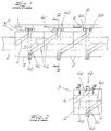
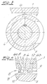
- the basic structure includes a drive shaft 2, a spatial cam mechanism 3 with a web cam 4 on the drive shaft 2 and a workpiece carrier guide device 5, for which reference is made to FIGS. 3 and 4.
- the workpiece carriers 1 have two rollers 6 guided on the web curve 4 on the cam gear side.
- the land curve 4 of the spatial cam mechanism 3 consists of a transport section 4a with a helical slope and a slope-free positioning and rest section 4b.
- the transport section 4a and the positioning and rest section 4b are connected to one another with a curved transition web section 4c.
- the land curve 4 of the spatial cam mechanism 3 is arranged on a plurality of hollow-shaft modules 7, each of which adjoins a full positioning and rest section 4b and on both sides to the positioning and rest section 4b a section of the Transport section 4a.
- the transport section 4a is preferably divided in half, as is also indicated by the figures.
- the modules 7 are pushed onto the drive shaft 2 in a rotationally fixed manner and fastened to the transport sections 4a by abutting sections thereof.
- the rotationally fixed connection of the modules 7 on the drive shaft 2 can be seen in FIG. 3.
- Fig. 1 it was indicated that one of the two rollers 6 of the workpiece carrier 1 is designed as a guide roller 6a with a fixed axis 8, while the other is designed as a biasing roller 6b with a biasing spring 9.
- the preload acts in the direction of the arrow.
- the biasing roller 6b presses the guide roller 6a against the associated guide surface 10 of the web curve 4.
- the curvature of the transition web sections 4c and the connection areas of the transition web sections 4c to the assigned parts of the web curve 4 and the pretensioning force of the pretensioning spring 9 are coordinated with one another in such a way that the movement of the workpiece carrier 1 takes place with sufficient vibration and that the first time derivative of the movement curve of the workpiece carrier 1 in this area is practically constant.
- the coordination is of course taking into account the moving mass and the transport speed. The coordination can be carried out arithmetically using the tools of modern technical mechanics or in the laboratory.
- the transport sections 4a have a constant slope S.
- the person skilled in the art recognizes in the figures that the sections of abutting modules 7 form transport sections 4a, which could also have a different slope S from module pair to module pair.
- the positioning and resting sections 4b of modules that abut each other could have a different length from module 7 to module 7.
- the figures also show that the modules 7 can be easily replaced, this also applies to the bias springs 9, which can also be adjustable.
- the guide surfaces 10 of the web curve 4 are machined with particularly low tolerances and special surface quality.
- Fig. 4 it was indicated that the guide roller 6a with a fixed axis 8 has an axle bolt 11, which is inserted into a bore of the associated workpiece holder 1 and the bore passes through, the axle bolt 11 on the workpiece holder 1 the positioning fixed point for a Workpiece carrier arranged workpiece nest forms.
- the modules 7 placed against one another are face-ground on the end face and braced against one another.
Landscapes
- Engineering & Computer Science (AREA)
- Mechanical Engineering (AREA)
- General Engineering & Computer Science (AREA)
- Advancing Webs (AREA)
- Transmission Devices (AREA)
- Automatic Assembly (AREA)
- Chain Conveyers (AREA)
- Replacement Of Web Rolls (AREA)
Applications Claiming Priority (4)
| Application Number | Priority Date | Filing Date | Title |
|---|---|---|---|
| DE4308576 | 1993-03-18 | ||
| DE4308576 | 1993-03-18 | ||
| DE4316556 | 1993-05-18 | ||
| DE4316556A DE4316556C2 (de) | 1993-03-18 | 1993-05-18 | Vorrichtung für den Transport und die Positionierung von Werkstückträgern, die als Lineareinheit ausgeführt ist |
Publications (2)
| Publication Number | Publication Date |
|---|---|
| EP0620080A1 EP0620080A1 (de) | 1994-10-19 |
| EP0620080B1 true EP0620080B1 (de) | 1996-03-20 |
Family
ID=25924048
Family Applications (1)
| Application Number | Title | Priority Date | Filing Date |
|---|---|---|---|
| EP94100322A Expired - Lifetime EP0620080B1 (de) | 1993-03-18 | 1994-01-12 | Vorrichtung für den Transport und die Positionierung von Werkstückträgern, die als Lineareinheit ausgeführt ist |
Country Status (5)
| Country | Link |
|---|---|
| EP (1) | EP0620080B1 (da) |
| AT (1) | ATE135616T1 (da) |
| DE (1) | DE4316556C2 (da) |
| DK (1) | DK0620080T3 (da) |
| ES (1) | ES2086238T3 (da) |
Families Citing this family (4)
| Publication number | Priority date | Publication date | Assignee | Title |
|---|---|---|---|---|
| JP4538212B2 (ja) * | 2002-10-24 | 2010-09-08 | 株式会社三共製作所 | 駆動機構およびこれを用いた移動テーブル |
| EP2403785B1 (en) | 2009-03-03 | 2013-05-01 | ATS Automation Tooling Systems Inc. | Multi-mode and multi-pitch conveyor system |
| CN106438896B (zh) * | 2016-08-15 | 2018-08-17 | 济南大学 | 一种实现直线间歇进给的凸轮机构 |
| DE102017116414A1 (de) | 2017-07-20 | 2019-01-24 | Weiss Gmbh | Transportvorrichtung zur rotatorischen und/oder linearen bewegung eines werkstücks |
Family Cites Families (9)
| Publication number | Priority date | Publication date | Assignee | Title |
|---|---|---|---|---|
| US2789683A (en) * | 1953-10-02 | 1957-04-23 | Gen Electric | Work indexing arrangement |
| DE1969057U (de) * | 1967-05-30 | 1967-09-21 | Bayer Ag | Foerderschnecke. |
| JPS4947354B1 (da) * | 1969-10-02 | 1974-12-14 | ||
| FR2156497A1 (da) * | 1971-10-22 | 1973-06-01 | Automatisme Tech | |
| DE2513701A1 (de) * | 1975-03-27 | 1976-10-07 | Peter Balleis | Insbesondere fuer spielzeuge bestimmte archimedische schraube aus kunststoff und verfahren zu ihrer herstellung |
| AU534741B2 (en) * | 1978-04-24 | 1984-02-16 | Yoshino Kogyosho Co., Ltd. | A device for conveying and aligning bottle-shaped containers |
| DE3209595A1 (de) * | 1982-03-17 | 1983-10-06 | Benz & Hilgers Gmbh | Maschine zum abfuellen und verpacken von nahrungsmitteln |
| EP0424562B1 (de) * | 1989-10-25 | 1992-02-26 | Dieter Weiss | Palettenwechsler für einen linearen Horizontalförderer |
| DE9015999U1 (de) * | 1990-11-16 | 1991-03-28 | Petkus GmbH Getreide- und Saatgutaufbereitungstechnik, O-5909 Wutha | Schnecke aus Plastsegmenten |
-
1993
- 1993-05-18 DE DE4316556A patent/DE4316556C2/de not_active Expired - Fee Related
-
1994
- 1994-01-12 ES ES94100322T patent/ES2086238T3/es not_active Expired - Lifetime
- 1994-01-12 AT AT94100322T patent/ATE135616T1/de not_active IP Right Cessation
- 1994-01-12 EP EP94100322A patent/EP0620080B1/de not_active Expired - Lifetime
- 1994-01-12 DK DK94100322.0T patent/DK0620080T3/da active
Also Published As
| Publication number | Publication date |
|---|---|
| DE4316556C2 (de) | 1995-08-31 |
| DE4316556A1 (de) | 1994-09-22 |
| EP0620080A1 (de) | 1994-10-19 |
| ES2086238T3 (es) | 1996-06-16 |
| ATE135616T1 (de) | 1996-04-15 |
| DK0620080T3 (da) | 1996-06-03 |
Similar Documents
| Publication | Publication Date | Title |
|---|---|---|
| DE19983512B3 (de) | Elektrisches Stellglied | |
| DE68907028T2 (de) | Mikroschlaggeraet fuer markierung. | |
| DE4224032A1 (de) | Antriebssystem | |
| DE19536514C2 (de) | Werkzeug-Wechselvorrichtung zum Wechseln der Werkzeuge eines Bearbeitungszentrums | |
| DE19821763B4 (de) | Vorschubeinrichtung für eine Industriemaschine und Industriemaschine, die diese verwendet | |
| DE3139031C1 (de) | Antriebsvorrichtung am Koordinatentisch einer Bearbeitungsmaschine fuer einen Schlitten | |
| EP0127576A1 (de) | Linear-Antriebsvorrichtung mit zwei Motoren | |
| DE4430388A1 (de) | Stellantrieb für einen Schlitten in einer Maschine, insbesondere Werkzeugmaschine | |
| DE2727645C3 (de) | Bearbeitungseinheit, insbesondere für Transfermaschinen | |
| DE2618846B2 (de) | Biegemaschine zum Herstellen von Formteilen aus Metalldraht oder -band | |
| DE4320501C2 (de) | Anlage für die Bearbeitung und/oder Montage von auf einem Werkstückträger angeordneten Werkstücken | |
| DE4316556C2 (de) | Vorrichtung für den Transport und die Positionierung von Werkstückträgern, die als Lineareinheit ausgeführt ist | |
| DE2006760A1 (de) | Unrunddrehemrichtung fur Drehmaschinen | |
| DE19725033C1 (de) | Automatische Biegerichtmaschine | |
| EP0069274B1 (de) | Wälzgetriebe bei einer Verzahnungsmaschine für Evolventenverzahnung | |
| EP0623533A1 (de) | Verfahren und Fördereinrichtung zum Transportieren von Werkstückträgern | |
| DE4303526C2 (de) | Verfahren und Vorrichtung zur Honbearbeitung von Werkstücken | |
| EP0275867A1 (de) | Vorrichtung zur geradlinigen Bewegung von Teilen oder Gegenständen | |
| DE4328983A1 (de) | Anlage für die Bearbeitung und/oder Montage von auf einem Werkstückträger angeordneten Werkstücken | |
| DE3644391A1 (de) | Beschriftungsvorrichtung | |
| DE2630224A1 (de) | Verfahren zum montieren von streckwerken auf einer streckwerksbank | |
| DD300155A7 (de) | Vorrichtung zum Antrieb und zur Führung einer Schneidbrücke | |
| DE29501631U1 (de) | Zuführ- und/oder Abführvorrichtung für Drehteile, die spitzenlos in einer Schleifmaschine an ihrer Außenseite geschliffen werden | |
| DE2823298C2 (de) | Kopiervorrichtung für Werkzeugmaschinen | |
| DE2502787C3 (de) | Einstellvorrichtung für ein Arbeitsglied, insbesondere für das Aufnahmeglied eines Summentypenträgers einer Schreib- oder ähnlichen Büromaschine |
Legal Events
| Date | Code | Title | Description |
|---|---|---|---|
| PUAI | Public reference made under article 153(3) epc to a published international application that has entered the european phase |
Free format text: ORIGINAL CODE: 0009012 |
|
| 17P | Request for examination filed |
Effective date: 19940112 |
|
| AK | Designated contracting states |
Kind code of ref document: A1 Designated state(s): AT BE CH DK ES FR GB IT LI NL PT SE |
|
| 17Q | First examination report despatched |
Effective date: 19950214 |
|
| GRAH | Despatch of communication of intention to grant a patent |
Free format text: ORIGINAL CODE: EPIDOS IGRA |
|
| GRAA | (expected) grant |
Free format text: ORIGINAL CODE: 0009210 |
|
| AK | Designated contracting states |
Kind code of ref document: B1 Designated state(s): AT BE CH DK ES FR GB IT LI NL PT SE |
|
| REF | Corresponds to: |
Ref document number: 135616 Country of ref document: AT Date of ref document: 19960415 Kind code of ref document: T |
|
| REG | Reference to a national code |
Ref country code: CH Ref legal event code: NV Representative=s name: KELLER & PARTNER PATENTANWAELTE AG |
|
| ITF | It: translation for a ep patent filed | ||
| GBT | Gb: translation of ep patent filed (gb section 77(6)(a)/1977) |
Effective date: 19960426 |
|
| REG | Reference to a national code |
Ref country code: DK Ref legal event code: T3 |
|
| REG | Reference to a national code |
Ref country code: ES Ref legal event code: FG2A Ref document number: 2086238 Country of ref document: ES Kind code of ref document: T3 |
|
| ET | Fr: translation filed | ||
| SC4A | Pt: translation is available |
Free format text: 960415 AVAILABILITY OF NATIONAL TRANSLATION |
|
| PGFP | Annual fee paid to national office [announced via postgrant information from national office to epo] |
Ref country code: PT Payment date: 19960805 Year of fee payment: 4 |
|
| PG25 | Lapsed in a contracting state [announced via postgrant information from national office to epo] |
Ref country code: DK Effective date: 19970112 Ref country code: AT Free format text: LAPSE BECAUSE OF NON-PAYMENT OF DUE FEES Effective date: 19970112 |
|
| REG | Reference to a national code |
Ref country code: DK Ref legal event code: EBP |
|
| PG25 | Lapsed in a contracting state [announced via postgrant information from national office to epo] |
Ref country code: SE Effective date: 19970113 Ref country code: ES Free format text: LAPSE BECAUSE OF NON-PAYMENT OF DUE FEES Effective date: 19970113 |
|
| PLBE | No opposition filed within time limit |
Free format text: ORIGINAL CODE: 0009261 |
|
| STAA | Information on the status of an ep patent application or granted ep patent |
Free format text: STATUS: NO OPPOSITION FILED WITHIN TIME LIMIT |
|
| PG25 | Lapsed in a contracting state [announced via postgrant information from national office to epo] |
Ref country code: LI Effective date: 19970131 Ref country code: CH Effective date: 19970131 Ref country code: BE Effective date: 19970131 |
|
| 26N | No opposition filed | ||
| BERE | Be: lapsed |
Owner name: SIM ZUFUHR-UND MONTAGETECHNIK G.M.B.H. & CO. K.G. Effective date: 19970131 |
|
| REG | Reference to a national code |
Ref country code: CH Ref legal event code: PL |
|
| PG25 | Lapsed in a contracting state [announced via postgrant information from national office to epo] |
Ref country code: FR Effective date: 19970930 |
|
| EUG | Se: european patent has lapsed |
Ref document number: 94100322.0 |
|
| REG | Reference to a national code |
Ref country code: FR Ref legal event code: ST |
|
| PG25 | Lapsed in a contracting state [announced via postgrant information from national office to epo] |
Ref country code: GB Free format text: LAPSE BECAUSE OF NON-PAYMENT OF DUE FEES Effective date: 19980112 |
|
| PG25 | Lapsed in a contracting state [announced via postgrant information from national office to epo] |
Ref country code: PT Free format text: LAPSE BECAUSE OF NON-PAYMENT OF DUE FEES Effective date: 19980731 |
|
| PG25 | Lapsed in a contracting state [announced via postgrant information from national office to epo] |
Ref country code: NL Free format text: LAPSE BECAUSE OF NON-PAYMENT OF DUE FEES Effective date: 19980801 |
|
| GBPC | Gb: european patent ceased through non-payment of renewal fee |
Effective date: 19980112 |
|
| NLV4 | Nl: lapsed or anulled due to non-payment of the annual fee |
Effective date: 19980801 |
|
| REG | Reference to a national code |
Ref country code: PT Ref legal event code: MM4A Free format text: LAPSE DUE TO NON-PAYMENT OF FEES Effective date: 19980731 |
|
| REG | Reference to a national code |
Ref country code: ES Ref legal event code: FD2A Effective date: 20021016 |
|
| PG25 | Lapsed in a contracting state [announced via postgrant information from national office to epo] |
Ref country code: IT Free format text: LAPSE BECAUSE OF NON-PAYMENT OF DUE FEES Effective date: 20050112 |