EP0620075A2 - Torche de soudage à l'arc pour le soudage sous gaz protecteur - Google Patents
Torche de soudage à l'arc pour le soudage sous gaz protecteur Download PDFInfo
- Publication number
- EP0620075A2 EP0620075A2 EP94104464A EP94104464A EP0620075A2 EP 0620075 A2 EP0620075 A2 EP 0620075A2 EP 94104464 A EP94104464 A EP 94104464A EP 94104464 A EP94104464 A EP 94104464A EP 0620075 A2 EP0620075 A2 EP 0620075A2
- Authority
- EP
- European Patent Office
- Prior art keywords
- receptacle
- contact tip
- welding torch
- arc welding
- contact
- Prior art date
- Legal status (The legal status is an assumption and is not a legal conclusion. Google has not performed a legal analysis and makes no representation as to the accuracy of the status listed.)
- Granted
Links
Images


Classifications
-
- B—PERFORMING OPERATIONS; TRANSPORTING
- B23—MACHINE TOOLS; METAL-WORKING NOT OTHERWISE PROVIDED FOR
- B23K—SOLDERING OR UNSOLDERING; WELDING; CLADDING OR PLATING BY SOLDERING OR WELDING; CUTTING BY APPLYING HEAT LOCALLY, e.g. FLAME CUTTING; WORKING BY LASER BEAM
- B23K9/00—Arc welding or cutting
- B23K9/24—Features related to electrodes
- B23K9/28—Supporting devices for electrodes
- B23K9/29—Supporting devices adapted for making use of shielding means
- B23K9/291—Supporting devices adapted for making use of shielding means the shielding means being a gas
- B23K9/295—Supporting devices adapted for making use of shielding means the shielding means being a gas using consumable electrode-wire
Definitions
- the invention relates to an arc welding torch according to the preamble of claim 1.
- the components of the welding torch namely the contact tip, an insert which may be present in the contact tip and the gas nozzle, are detachably connected to their corresponding receiving parts.
- the invention is an object of the invention to provide an arc welding torch of the type mentioned, in which the attachment of the components mentioned, namely the contact tip, and any insert and a gas nozzle, is designed so that for good heat conduction and yet for easy and quick attachment and a corresponding release is provided if this is desired.
- the rotary cone according to the invention can therefore be used in different ways.
- a rotating cone can be provided between one or more of the components mentioned. It is also possible to use a rotating cone for fastening one of the components mentioned, and to fasten the other components in a conventional manner by means of a thread or a plug-in cone.
- the rotary cone is advantageously used for all existing components for which such a type of fastening is advantageous, taking into account the desired heat conduction and releasable fastening.
- longitudinal slots can be provided in the area of the contact surfaces which are used to conduct protective gas. These longitudinal slots can be introduced separately, or can simply be the spaces that remain when turning in the closing direction.
- the principle of the rotating cone, formed by the spiral segment surfaces is not only directly in the welding torch in the area of the welding technology mentioned here, i.e. can be used in the welding tool, but also with quick-action couplings for the transmission of current and / or heat in the supply line between the welding current source and the welding torch, the separation point being able to be provided on the welding machine, in the hose package or in the welding gun head itself.
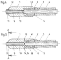
- the welding torch has a contact tip 1 which is fastened on a receptacle 2.
- the coolant flows through a pipe 3 and a pipe 4 to a coolant ring channel 5 in the receptacle 2 and back again.
- the contact tip is fastened to the receptacle 2 by means of a rotating cone, which is formed by spiral contact surfaces 7, 8 is formed, as is best seen when looking at Figs. 2 and 3.
- These contact surfaces 7 and 8 have, as a common center, the center line of the welding wire bore 9 which can be seen in cross section.
- the segment surfaces 7 and 8 are always equally spaced from the center line of the welding wire bore 9, ie they practically form cylindrical surfaces.
- the contact tip 1 can be plugged onto the receptacle 2 unhindered.
- a small angle, which is shown in FIG. 3, is then used for fastening.
- the segment surfaces 7 and 8 come into contact with one another, ie they "wedge". A large-area contact is created, which ensures good heat conduction and secure fastening, which can be released again at the same time.
- the contact tip surrounds the coolant ring channel 5 with its end facing the tube 3, 4, the rotating cone connection in this area ensuring good heat transfer and secure attachment.
- an insert 10 can be secured in an inner bore of the contact tip, as shown in FIG. 1.
- This insert is a wearing part that can be replaced.
- the insert can therefore be designed specifically for its task of being a wearing part, i.e. consist of appropriate materials.
- the insert is advantageously fastened on the same principle as the contact tip, namely with the aid of a rotating cone which is designed as shown in FIGS. 6 and 7.
- the spiral segment surfaces are designated 14 and 15.
- an attack 11 is provided for a tool. This allows the fixed Connection can be achieved by slight twisting, that is to assume the position shown in Fig. 7. Conversely, this connection can be released again when the insert is to be replaced.
- the embodiment according to FIG. 4 shows a contact tip 1, which is also attached to the receptacle 2 with the aid of a rotating cone (segment surfaces 7, 8).
- the insert 10 is fastened differently than in the embodiment according to FIG. 1, namely with the aid of a plug-in cone and a thread 12 in the front area.
- the insert is fastened with the aid of a rotating cone (segment surfaces 14, 15).
- the contact tip 1 is fastened to the receptacle 2 with the aid of a plug-in cone connection 18, 19 and a thread 6.
- a transverse bore 13 is provided for the passage of protective gas.
- FIG. 8 basically corresponds to that according to FIG. 1, but with a gas nozzle 16 attached to a tubular gas nozzle receptacle 23, again with the aid of a rotating cone which corresponds to that described above and is shown in FIGS. 9 and 10 .
- the segment surfaces are designated 20 and 21.
- the gas nozzle 16 is electrically isolated from the tubes 3 and 4 by an insulating ring 22.
- the protective gas line takes place through an annular channel on the outside of the tube 4 to openings 17 and from there into the area of the gas nozzle 16, ie into the annular space between the gas nozzle 16 and the contact tip 1.
- a second cooling circuit 25 is provided, which cools the gas nozzle receptacle 23 serves.
- the inner part is formed in its outer contour (segment surface 15) with three spiral segments of 120 ° each.
- the distance of the surface line of each segment from a common center per angular step increases by a certain value in relation to the radius.
- an inclined plane would result as a development, the slope in the above-mentioned embodiments is approximately 5%.
- the inner contour (segment surface 14) of the outer part (contact tip 1) is designed in the same way, but with an initial value enlarged by a certain gap.
- the size of the gap is selected so that the inner part can be easily inserted into the outer part, taking into account the manufacturing tolerances.
- Both the inner and outer part are designed with a cylindrical cross-section that is constant in their length.
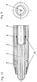
- FIGS. 11 and 12 differs from the embodiments illustrated in the other figures in that the receptacle 2 with the coolant ring channel 5 surrounds the contact tip on the outside, so that the contact surfaces, which are designed as a rotating cone with the spiral segment surfaces, are on the inside of the holder and on the outside of the contact tip.
- the receptacle 2 consists of tubes 3, 4, which are assembled by solder rings 26.
- the contact tip is surrounded over most of its longitudinal extent by the coolant ring channel 5, so that very good heat dissipation via the rotating cone and a short heat transfer surface in the radial direction are ensured.
Landscapes
- Engineering & Computer Science (AREA)
- Physics & Mathematics (AREA)
- Plasma & Fusion (AREA)
- Mechanical Engineering (AREA)
- Arc Welding In General (AREA)
Applications Claiming Priority (2)
| Application Number | Priority Date | Filing Date | Title |
|---|---|---|---|
| DE4312167A DE4312167A1 (de) | 1993-04-14 | 1993-04-14 | Lichtbogenschweißbrenner zum Schutzgasschweißen |
| DE4312167 | 1993-04-14 |
Publications (3)
| Publication Number | Publication Date |
|---|---|
| EP0620075A2 true EP0620075A2 (fr) | 1994-10-19 |
| EP0620075A3 EP0620075A3 (fr) | 1995-08-09 |
| EP0620075B1 EP0620075B1 (fr) | 1996-12-27 |
Family
ID=6485445
Family Applications (1)
| Application Number | Title | Priority Date | Filing Date |
|---|---|---|---|
| EP94104464A Expired - Lifetime EP0620075B1 (fr) | 1993-04-14 | 1994-03-22 | Torche de soudage à l'arc pour le soudage sous gaz protecteur |
Country Status (3)
| Country | Link |
|---|---|
| EP (1) | EP0620075B1 (fr) |
| AT (1) | ATE146713T1 (fr) |
| DE (2) | DE4312167A1 (fr) |
Cited By (1)
| Publication number | Priority date | Publication date | Assignee | Title |
|---|---|---|---|---|
| WO2009092125A1 (fr) * | 2008-01-23 | 2009-07-30 | Fronius International Gmbh | Système de fixation d'une buse à gaz |
Citations (2)
| Publication number | Priority date | Publication date | Assignee | Title |
|---|---|---|---|---|
| DE2631742A1 (de) * | 1976-07-15 | 1978-01-19 | Wilhelm Dinse | Schweisswerkzeug zum elektroschweissen |
| WO1992016763A1 (fr) * | 1991-03-22 | 1992-10-01 | Kuehl Hans | Liaison arbre-moyeu |
-
1993
- 1993-04-14 DE DE4312167A patent/DE4312167A1/de not_active Withdrawn
-
1994
- 1994-03-22 EP EP94104464A patent/EP0620075B1/fr not_active Expired - Lifetime
- 1994-03-22 DE DE59401373T patent/DE59401373D1/de not_active Expired - Lifetime
- 1994-03-22 AT AT94104464T patent/ATE146713T1/de not_active IP Right Cessation
Patent Citations (2)
| Publication number | Priority date | Publication date | Assignee | Title |
|---|---|---|---|---|
| DE2631742A1 (de) * | 1976-07-15 | 1978-01-19 | Wilhelm Dinse | Schweisswerkzeug zum elektroschweissen |
| WO1992016763A1 (fr) * | 1991-03-22 | 1992-10-01 | Kuehl Hans | Liaison arbre-moyeu |
Cited By (3)
| Publication number | Priority date | Publication date | Assignee | Title |
|---|---|---|---|---|
| WO2009092125A1 (fr) * | 2008-01-23 | 2009-07-30 | Fronius International Gmbh | Système de fixation d'une buse à gaz |
| RU2496619C2 (ru) * | 2008-01-23 | 2013-10-27 | Фрониус Интернациональ Гмбх | Крепление газовой форсунки |
| US8567826B2 (en) | 2008-01-23 | 2013-10-29 | Fronius International Gmbh | Gas nozzle attachment |
Also Published As
| Publication number | Publication date |
|---|---|
| DE4312167A1 (de) | 1994-10-20 |
| EP0620075A3 (fr) | 1995-08-09 |
| DE59401373D1 (de) | 1997-02-06 |
| ATE146713T1 (de) | 1997-01-15 |
| EP0620075B1 (fr) | 1996-12-27 |
Similar Documents
| Publication | Publication Date | Title |
|---|---|---|
| EP2349628B1 (fr) | Dispositif et procédé pour la mise en contact d'une baguette de soudure et coque de contact | |
| DE202013102979U1 (de) | Schweißbrenner für das Lichtbogen-Schutzgasschweißen und Kontaktrohr für einen solchen Schweißbrenner | |
| DE2807686C2 (de) | Schweißbrenner zum Lichtbogenschweißen mit abschmelzender Drahtelektrode | |
| DE202009018173U1 (de) | Düsenschutzkappe und Düsenschutzkappenhalter sowie Lichtbogenplasmabrenner mit derselben und/oder demselben | |
| DE3305521A1 (de) | Schweisspistole | |
| DE102007005316B4 (de) | Verbindung zwischen einem Plasmabrennerverschleißteil und einer Plasmabrennerverschleißteilhalterung, Plasmabrennerverschleißteil und Plasmabrennerverschleißteilhalterung | |
| DE102004044267A1 (de) | Spannmutter als Werkzeughalterteil für ein Werkzeug | |
| EP0620075B1 (fr) | Torche de soudage à l'arc pour le soudage sous gaz protecteur | |
| DE2631742A1 (de) | Schweisswerkzeug zum elektroschweissen | |
| DE10338773B4 (de) | Schweißbrenner-Bauteilkombination, Schweißbrenner und Schweißsystem | |
| EP3402024A1 (fr) | Dispositif de traitement de câbles | |
| DE4314099C2 (de) | Lichtbogenschweiß- oder -schneidbrenner sowie Elektrodenhalter hierfür | |
| DE2920917C3 (de) | Schutzgasschweißbrenner | |
| AT261362B (de) | Ringförmiges Mehrzwerk-Trägergerät | |
| DE2334335B1 (de) | Stromduese fuer Schweisspistolen | |
| DE1565931A1 (de) | Schweisswerkzeug | |
| DE4314100C2 (de) | Schlauchpaket mit Versorgungsleitungen für flüssigkeitsgekühlte Lichtbogenschweiß- oder -schneidbrenner | |
| EP4082708A1 (fr) | Chalumeau de soudage à refroidissement au gaz | |
| DE10338774B4 (de) | Schweißbrennerelement, Bauteilkombination, Schweißbrenner und Schweißsystem | |
| DE102016125346B4 (de) | Kontaktrohr und Vorrichung zum Lichtbogendrahtspritzen | |
| EP2857136A1 (fr) | Support d'électrodes pour une torche de soudage et torche de soudage correspondante | |
| EP0576784B1 (fr) | Foret de perçage des trous de coulée des hauts fourneaux | |
| DE968531C (de) | Schutzgas-Lichtbogenschweissbrenner zur Aufnahme wahlweise von abschmelzenden oder nicht abschmelzenden Elektroden | |
| DE3620958C1 (en) | Resistance spot welding device | |
| DE944576C (de) | Elektrodenhalter mit auswechselbarer Klemmbacke |
Legal Events
| Date | Code | Title | Description |
|---|---|---|---|
| PUAI | Public reference made under article 153(3) epc to a published international application that has entered the european phase |
Free format text: ORIGINAL CODE: 0009012 |
|
| AK | Designated contracting states |
Kind code of ref document: A2 Designated state(s): AT CH DE ES FR GB IT LI NL SE |
|
| PUAL | Search report despatched |
Free format text: ORIGINAL CODE: 0009013 |
|
| AK | Designated contracting states |
Kind code of ref document: A3 Designated state(s): AT CH DE ES FR GB IT LI NL SE |
|
| 17P | Request for examination filed |
Effective date: 19960123 |
|
| GRAG | Despatch of communication of intention to grant |
Free format text: ORIGINAL CODE: EPIDOS AGRA |
|
| 17Q | First examination report despatched |
Effective date: 19960416 |
|
| GRAH | Despatch of communication of intention to grant a patent |
Free format text: ORIGINAL CODE: EPIDOS IGRA |
|
| GRAH | Despatch of communication of intention to grant a patent |
Free format text: ORIGINAL CODE: EPIDOS IGRA |
|
| GRAA | (expected) grant |
Free format text: ORIGINAL CODE: 0009210 |
|
| AK | Designated contracting states |
Kind code of ref document: B1 Designated state(s): AT CH DE ES FR GB IT LI NL SE |
|
| PG25 | Lapsed in a contracting state [announced via postgrant information from national office to epo] |
Ref country code: NL Free format text: LAPSE BECAUSE OF FAILURE TO SUBMIT A TRANSLATION OF THE DESCRIPTION OR TO PAY THE FEE WITHIN THE PRESCRIBED TIME-LIMIT Effective date: 19961227 Ref country code: IT Free format text: LAPSE BECAUSE OF FAILURE TO SUBMIT A TRANSLATION OF THE DESCRIPTION OR TO PAY THE FEE WITHIN THE PRE;WARNING: LAPSES OF ITALIAN PATENTS WITH EFFECTIVE DATE BEFORE 2007 MAY HAVE OCCURRED AT ANY TIME BEFORE 2007. THE CORRECT EFFECTIVE DATE MAY BE DIFFERENT FROM THE ONE RECORDED.SCRIBED TIME-LIMIT Effective date: 19961227 Ref country code: GB Effective date: 19961227 Ref country code: FR Effective date: 19961227 Ref country code: ES Free format text: THE PATENT HAS BEEN ANNULLED BY A DECISION OF A NATIONAL AUTHORITY Effective date: 19961227 |
|
| REF | Corresponds to: |
Ref document number: 146713 Country of ref document: AT Date of ref document: 19970115 Kind code of ref document: T |
|
| REF | Corresponds to: |
Ref document number: 59401373 Country of ref document: DE Date of ref document: 19970206 |
|
| PG25 | Lapsed in a contracting state [announced via postgrant information from national office to epo] |
Ref country code: AT Free format text: LAPSE BECAUSE OF NON-PAYMENT OF DUE FEES Effective date: 19970322 |
|
| PG25 | Lapsed in a contracting state [announced via postgrant information from national office to epo] |
Ref country code: SE Effective date: 19970327 |
|
| PG25 | Lapsed in a contracting state [announced via postgrant information from national office to epo] |
Ref country code: LI Effective date: 19970331 Ref country code: CH Effective date: 19970331 |
|
| EN | Fr: translation not filed | ||
| NLV1 | Nl: lapsed or annulled due to failure to fulfill the requirements of art. 29p and 29m of the patents act | ||
| GBV | Gb: ep patent (uk) treated as always having been void in accordance with gb section 77(7)/1977 [no translation filed] |
Effective date: 19961227 |
|
| PLBE | No opposition filed within time limit |
Free format text: ORIGINAL CODE: 0009261 |
|
| STAA | Information on the status of an ep patent application or granted ep patent |
Free format text: STATUS: NO OPPOSITION FILED WITHIN TIME LIMIT |
|
| REG | Reference to a national code |
Ref country code: CH Ref legal event code: PL |
|
| 26N | No opposition filed | ||
| PGFP | Annual fee paid to national office [announced via postgrant information from national office to epo] |
Ref country code: DE Payment date: 20130124 Year of fee payment: 20 |
|
| REG | Reference to a national code |
Ref country code: DE Ref legal event code: R071 Ref document number: 59401373 Country of ref document: DE |
|
| PG25 | Lapsed in a contracting state [announced via postgrant information from national office to epo] |
Ref country code: DE Free format text: LAPSE BECAUSE OF EXPIRATION OF PROTECTION Effective date: 20140325 |